the Creative Commons Attribution 4.0 License.
the Creative Commons Attribution 4.0 License.
 | 18 Jun 2020
Structure and kinematics of an extensional growth fold, Hadahid Fault System, Suez Rift, Egypt
Christopher A.-L. Jackson
Paul S. Whipp
Robert L. Gawthorpe
Matthew M. Lewis
Normal faulting drives extensional growth folding of the Earth's upper crust during continental extension, yet we know little of how fold geometry relates to the structural segmentation of the underlying fault. We use field data from the Hadahid Fault System, Suez Rift, Egypt, to investigate the geometry and kinematics of a large (30 km long, up to 2.5 km displacement), exceptionally well-exposed normal fault system and to test and develop models for extensional growth folding. The Hadahid Fault System comprises eight up to 5 km long segments that are defined by unbreached or breached monoclines. These segments are soft-linked, hard-linked, or defined by a more subtle along-strike transition in overall structural style. High overlap : separation (O:S) ratios between its segments suggest the Hadahid Fault System comprises a single, now hard-linked structure at depth. We demonstrate that a progressive loss of at-surface displacement along-strike of the Hadahid Fault System results in surface-breaking faults and breached monoclines being replaced by unbreached monoclines developed above blind faults. However, shorter along-strike length-scale variations in structural style also occur, with unbreached monoclines developed between breached monoclines. The origin of this variability is unclear, but it might reflect local variations in host rock material properties that drive short length-scale variations in fault propagation-to-slip ratio, and thus the timing and location of fold breaching. We show that folding is a key expression of the strain that accumulates in areas of continental extension, arguing that tectono-sedimentary models for rift development should capture the related structural complexity.
- Article
(30734 KB) - Full-text XML
- BibTeX
- EndNote


Stretching of the Earth's upper crust is invariably accommodated by the development of normal faults. Folds can also be locally important, with extensional growth folds (sensu Coleman et al., 2019) developing around the tips of propagating normal faults (Fig. 1) (e.g. Sterns, 1978; Patton, 1984; Withjack et al., 1990; Schlische, 1995; Gawthorpe et al., 1997; Pascoe et al., 1999; Keller and Lynch, 1999; Maurin and Niviere, 1999; Corfield and Sharp, 2000; Sharp et al., 2000; Withjack and Callaway, 2000; Willsey et al., 2002; Gawthorpe et al., 2003; Jackson et al., 2006; Ford et al., 2007; Cardozo, 2008; Ferrill and Morris, 2008; El-Wahed et al., 2010; Ferrill et al., 2007, 2012; Wilson et al., 2013; Deckers, 2015; Tavani et al., 2013, 2018; Tavani and Granado, 2015; Conneally et al., 2017). In two dimensions, extensional growth folds define upward-widening monoclines (Fig. 1a–c) (e.g. Schlische, 1995; Gawthorpe et al., 1997; Janecke et al., 1998; Khalil and McClay, 2002; Willsey et al., 2002). In three dimensions, extensional growth folds are typically characterized by a relatively smooth, along-strike transition from a breached monocline (i.e. a monocline cross-cut by a normal fault such that it is now defined by a footwall-anticline–hangingwall-syncline pair) to an unbreached monocline (Fig. 1d) (e.g. Gawthorpe et al., 1997; Lewis et al., 2015; Conneally et al., 2017).
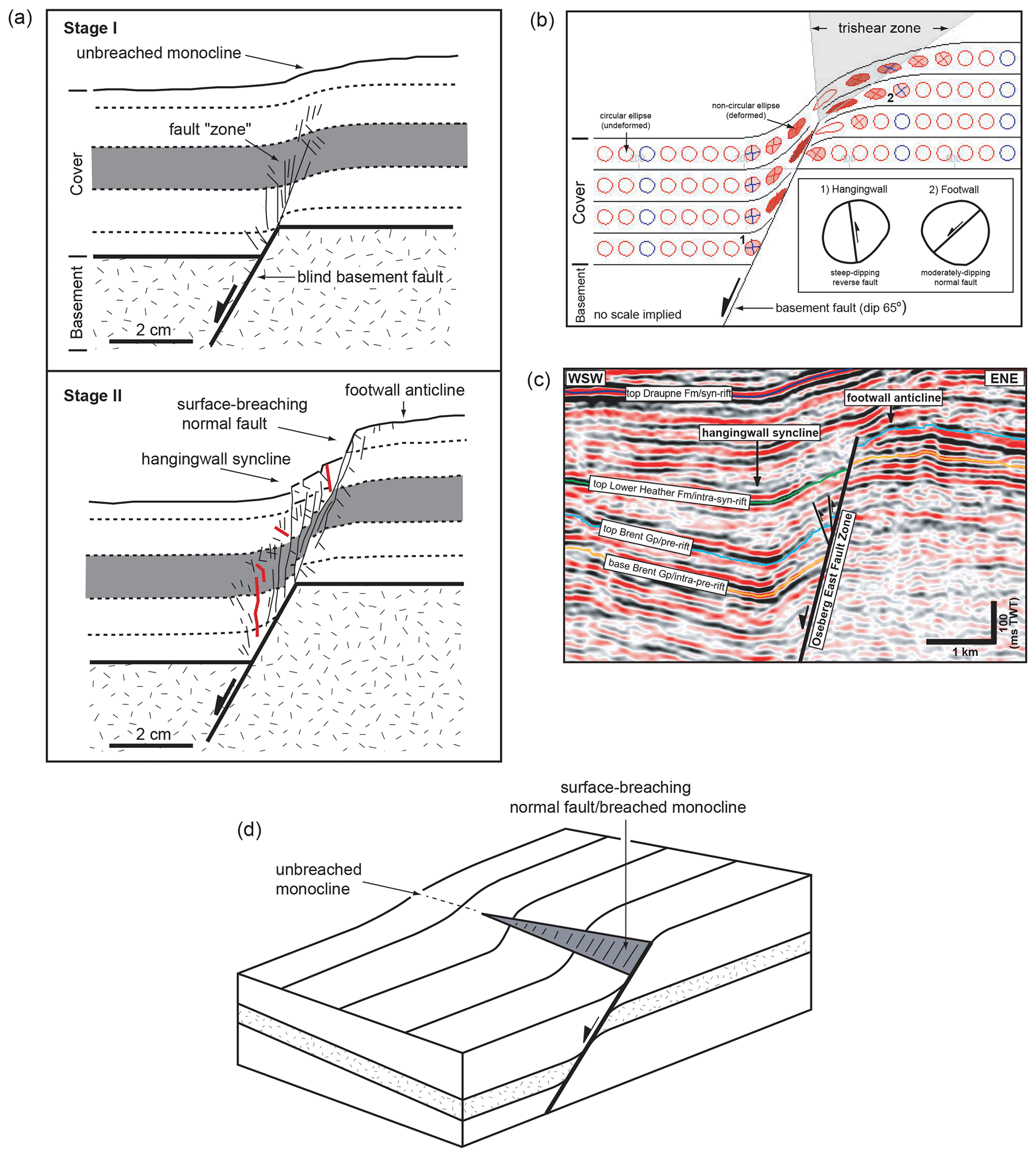
Figure 1(a) Physical analogue (clay) model showing the kinematic and structural development of an extensional growth fold (sensu Coleman et al., 2019) and associated secondary structures (modified from Withjack et al., 1990). Note the eventual development of a through-going “master” fault in Stage II; this fault breaches the overlying extensional growth fold, which during Stage I is characterized by a basinward-facing, unbreached monocline. Reverse faults are shown in red. (b) Result of a tri-shear-based model, showing the kinematic and structural development of an extensional forced fold (modified from Jackson et al., 2006) (based on the kinematic model of Allmendinger, 1998; see also Hardy and McClay, 1999). Note again the presence of steep-dipping reverse faults in the immediate (proto-)hangingwall of the through-going master fault. (c) Two-dimensional profile from a 3D seismic reflection volume from the northern North Sea, showing the final structure of a breached extensional fault-propagation fold. Note the development of reserve faults in the immediate hangingwall of the now through-going master fault. (d) Block diagram showing the change in structural style along-strike of a simple, isolated normal fault segment associated with extensional growth folding.
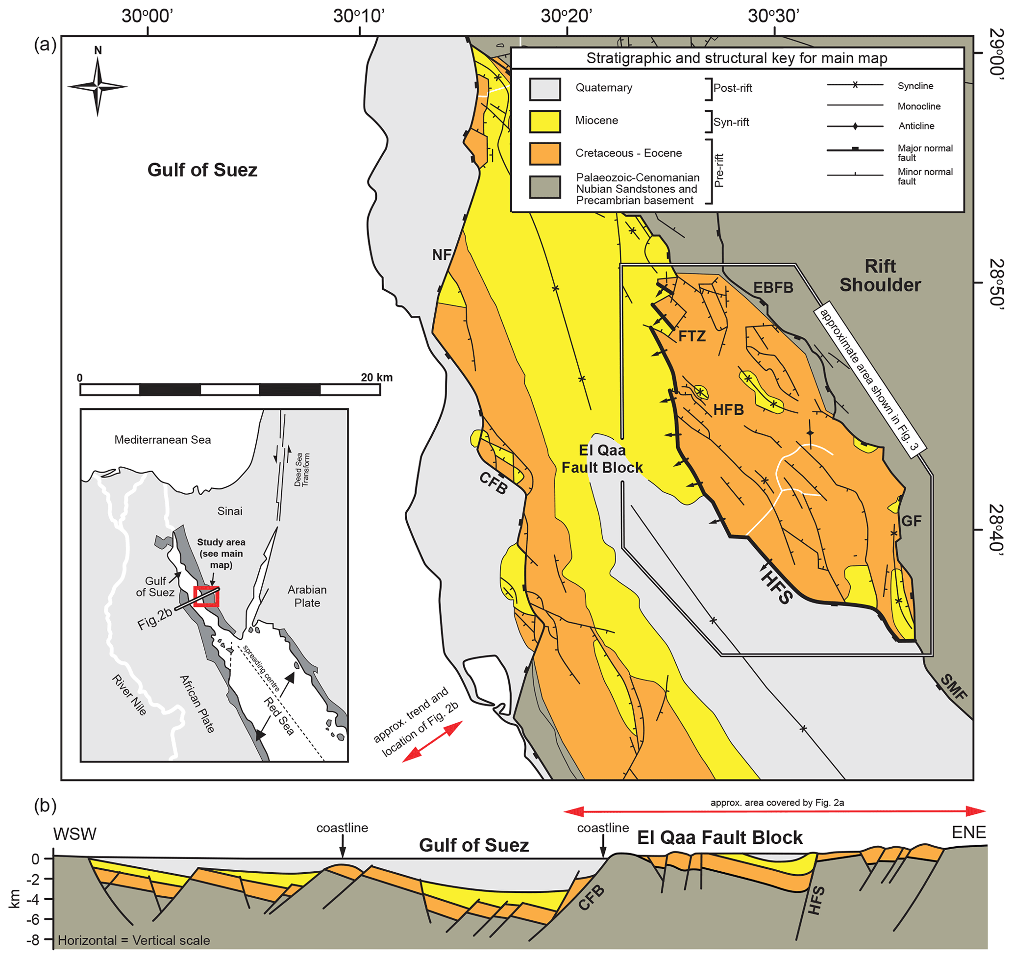
Figure 2(a) Simplified geologic map of the El Qaa Fault Block (modified from Moustafa and El-Raey, 1993, and Sharp et al., 2000). B-SF: Baba–Sidri Fault; NF: Nezzazat Fault; CFB: Coastal Fault Belt; FTZ: Feiran Transfer Zone; EBFB: Eastern Boundary Fault Belt; HFS: Hadahid Fault System; GF: Gebah Fault; SMF: Sinai Massif Fault; HFB: Hadahid Fault Block. Inset map shows the regional plate tectonic setting of the Gulf of Suez Rift. Dark-grey shading indicates area containing structures and stratigraphic units related to Oligo-Miocene rifting. (b) Geoseismic section across the central dip province of the Gulf of Suez Rift (modified from Patton et al., 1994). Location of the section is shown in (a).

Figure 3(a) Simplified geologic map of the Hadahid Fault Block (see Fig. 2a for location) (based on Moustafa and El-Raey, 1993 and new mapping undertaken as part of this study). The locations of cross section in Fig. 4 are indicated. (b) Simplified geological map highlighting the constituent segments of the Hadahid Fault System.
It is well known, however, that normal faults, rather than being represented by a single, relatively planar surface, are commonly segmented, being composed of numerous soft- or hard-linked segments that bifurcate during propagation in both dip and strike directions (e.g. Childs et al., 2003; Walsh et al., 1999, 2002, 2003; van der Zee and Urai, 2005; Schöpfer et al., 2006, 2007; Long and Imber, 2011; Giba et al., 2012; Jackson and Rotevatn, 2016; Fossen and Rotevatn, 2016; Freitag et al., 2017; Camanni et al., 2019). Because of this, fault tip lines can be highly irregular, reflecting spatial variations in host rock mechanical properties and related differences in propagation-to-slip ratio and/or spatially selective reactivation of pre-existing structures (e.g. Baudon and Cartwright, 2008). We may therefore expect that extensional growth folds will reflect the geometric and kinematic complexity of their causal normal faults. These folds should essentially be more complex than predicted by current models, which are largely based on studies of relatively small, geometrically simple fault segments (e.g. Gawthorpe et al., 1997; Sharp et al., 2000; Corfield and Sharp, 2002; Lewis et al., 2015).
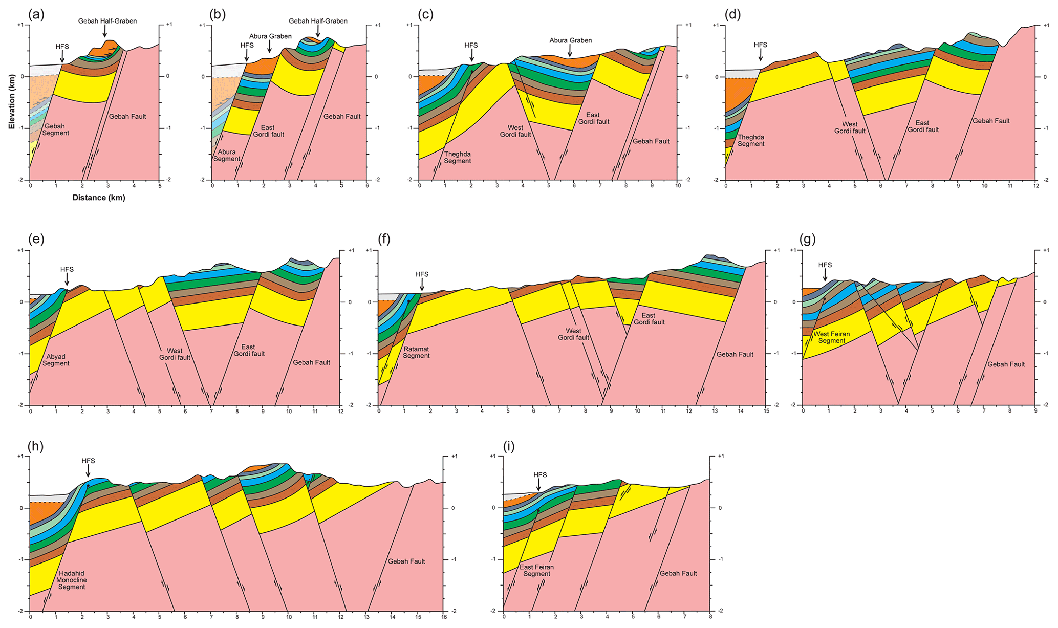
Figure 4Cross sections through the Hadahid Fault Block from south to north, based on the mapping of Moustafa and El-Raey (1993) and Sharp et al. (2000) and mapping undertaken as part of this study. Locations of the cross sections are shown in Fig. 3a. Vertical exaggeration: 2. Colour key to stratigraphic units is shown in Fig. 3a. The mapped and inferred location of the Hadahid Fault System is shown (see text for full discussion). Note that all topographic profiles shown here and in other figures are constructed using 30 m ASTM DEM data (vertical exaggeration: ×2). The geometry of the hangingwall of the Hadahid Fault System, especially on the southern segments, is largely unconstrained due to burial; it is inferred based on the measured thickness of the pre-rift succession (Fig. 3) and geometries predicted by physical and numerical models and observed in natural examples of extensional growth folds (Fig. 1).

Figure 5Composite stratigraphic section of the Hammam Faraun and El-Qaa fault blocks (modified from Moustafa, 1987). Mudstone-dominated units represent major layer-parallel slip horizons and are indicated by opposing black arrows. Bed thickness is based on measurements across the Hadahid Fault Block, with the recorded ranges being comparable to those reported by Moustafa and El-Raey (1993). The thickness of Megasequence 1 is taken from the Hammam Faraun Fault Block (Sharp et al., 2000), as the base of this interval is not exposed in the Hadahid Fault Block. Ages of key stratigraphic surfaces bounding early syn-rift units are also indicated (Bentham et al., 1996; Krebs et al., 1997).
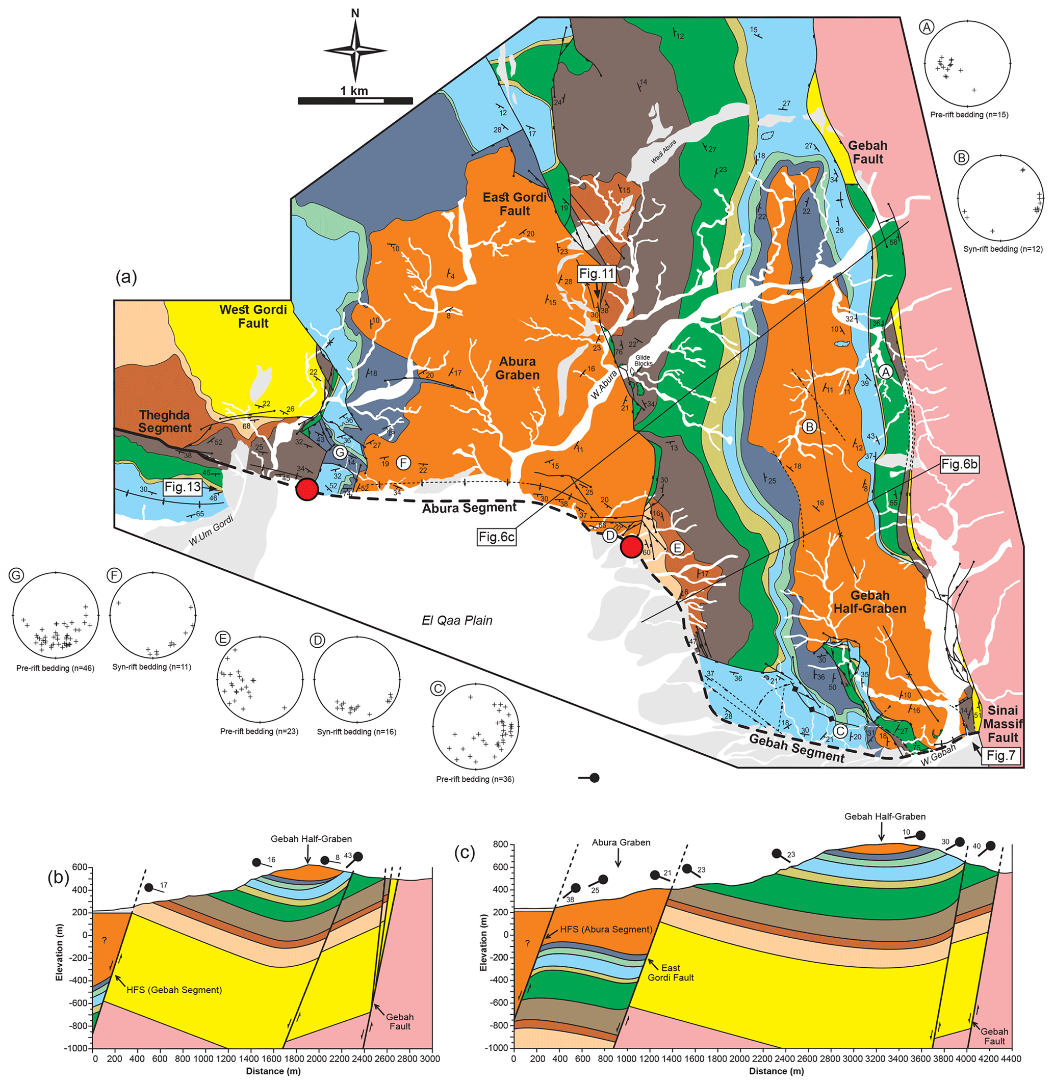
Figure 6(a) Field map of the southern end of the Hadahid Fault System, showing the Gebah and Abura segments. Colour key to stratigraphic units is shown in Fig. 3a. Red dots indicate the approximate boundaries between the identified segments. Lower-hemisphere projection stereonets summarize the dip and dip direction of pre- and syn-rift bedding (a–g; location shown on map). The location of the photographs shown in Figs. 7, 11, and 13 and the cross sections shown in (b) and (c) are indicated. (b) Down-plunge cross section across the Gebah Segment. (c) Down-plunge cross section across the Abura Segment.
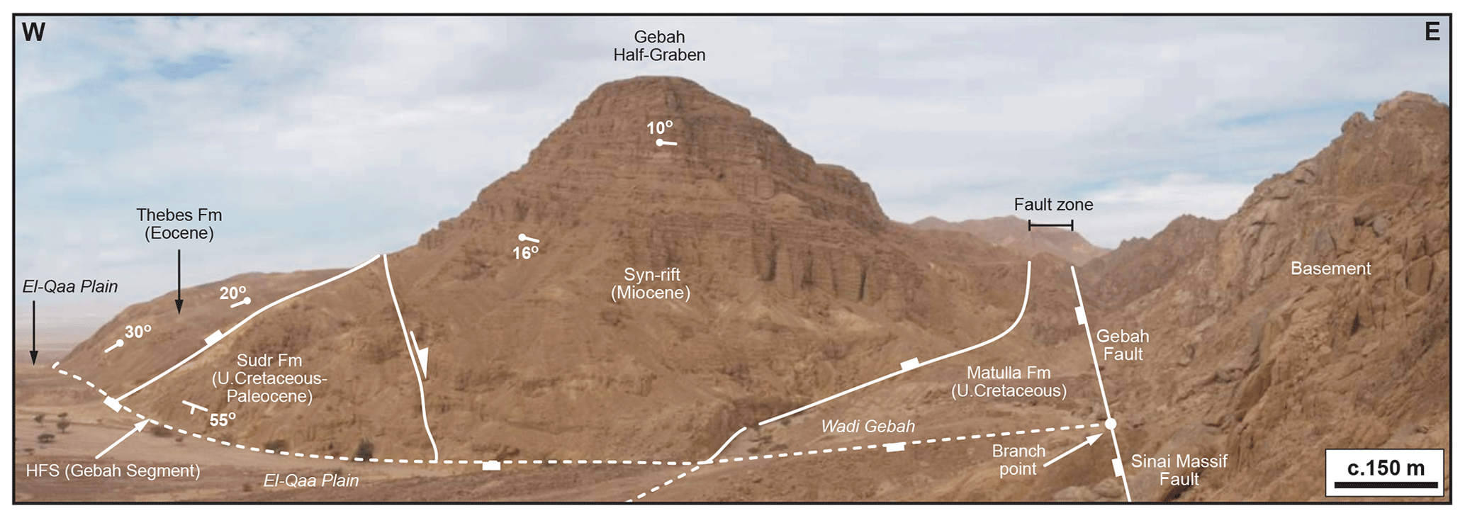
Figure 7Photograph looking northwards along the Sinai Massif and Gebah faults, showing the branch point with the Gebah Segment of the Hadahid Fault System. The location of the photo is shown in Fig. 6a.
Understanding the structure and kinematics of extensional growth folds is important. These structures, which are widespread in some rifts (e.g. Gulf of Suez; Moustafa, 1987; Withjack et al., 1990; Gawthorpe et al., 1997; Sharp et al., 2000; Jackson et al., 2006; El-Wahed et al., 2010; Lewis et al., 2015) and well-developed adjacent to certain faults in others (e.g. offshore western Norway; Pascoe et al., 1999; Corfield and Sharp, 2000; Bell et al., 2014; Whipp et al., 2014), control basin geometry, sediment dispersal, and, ultimately, the syn-rift stratigraphic record of continental extension (see review by Coleman et al., 2019). It is also critical to understand the origin and style of fold-related extensional strains (so-called “continuous deformation”; Walsh and Watterson, 1991) when reconstructing the growth of normal faults (see also Childs et al., 2017; Lăpădat al., 2017). Documenting the structure and kinematics of extensional growth folds is challenging given their size (i.e. they can have amplitudes of several tens to hundreds of metres, widths of several kilometres, and strike extents of several tens of kilometres) and three-dimensional complexity. They are therefore much larger than the typical size of many field exposures, which commonly permit only a depth-limited perspective of fold structure and growth, at one specific along-strike location (see Patton et al., 1994; Sharp et al., 2000 for exceptions). In contrast, high-quality, 3D seismic reflection data permit four-dimensional analysis of large extensional growth folds, although the impact of fault segmentation on fold geometry and kinematics has only very rarely been studied in detail (see Conneally et al., 2017). Here we use high-resolution field mapping (1 : 2000 and 1 : 5000 scale) to describe the geometric and kinematic development of the Hadahid Fault System, an exceptionally well-exposed, crustal-scale (30 km long, up to 2.5 km displacement) fault system located in the El-Qaa Fault Block, Suez Rift, Egypt (Figs. 2 and 3). Our data allow us to test and develop models for the development of extensional growth folds.
2.1 Regional tectonic and structural framework
The Neogene Suez Rift developed during late-Oligocene to early-Miocene (24–15.5 Ma) rifting of the African and Arabian plates (e.g. Garfunkel and Bartov, 1977; Colletta et al., 1988; Lyberis, 1988; Patton et al., 1994; Bosworth and McClay, 2001). The NW-trending Suez Rift is 300 km long and up to 80 km wide, representing the northern arm of the failed intra-continental Red Sea rift system (inset in Fig. 2a). The Suez Rift consists of several large, broadly NW–SE-striking normal fault systems that bound an up to 50 km long and 10–20 km wide half-graben (Fig. 2) (e.g. Bosworth, 1995; Moustafa, 1996; McClay et al., 1998; Bosworth and McClay, 2001).
2.2 Structural evolution of the El Qaa Fault Block and Hadahid Fault System
The El Qaa Fault Block is located on the Sinai margin of the Suez Rift. The fault block is defined by a 40 km long by 25 km wide half-graben, which is bound to the east and west by NW–SE-to-NNW–SSE-striking, W-dipping, large displacement (up to 5 km) normal faults (e.g. Eastern Boundary and Coastal fault belts and the Nezzazat, Sinai Massif, and Gebah faults; Figs. 2–4) (sensu Sharp et al., 2000; see also Moustafa and El-Raey, 1993; Patton et al., 1994). This study focuses on the Hadahid Fault System, an intra-half-graben fault bounding the south-western margin of the Hadahid Fault Block (Fig. 3) (e.g. Moustafa and El-Raey, 1993). The Feiran Transfer Zone defines the northern limit of the Hadahid Fault System; here, displacement is transferred north-eastwards onto the Baba–Sidri Fault via several broadly NW-striking, SW-dipping, moderate displacement (<500 m) normal faults (Fig. 2) (e.g. Moustafa, 1992; Moustafa and El-Raey, 1993; Sharp et al., 2000). The Hadahid Fault System is defined by several unbreached (Figs. 3, and 4c, g, h and i) and breached (Figs. 3, and 4a, b, d–f) forced folds (e.g. Patton, 1984; Withjack et al., 1990; Gawthorpe et al., 1997; Gupta et al., 1999; Sharp et al., 2000; Jackson et al., 2006; Lewis et al., 2015). The detailed structure and evolution of the Hadahid Fault System forms the focus of this study.

Figure 8(a) Field map of the Theghda Segment of the Hadahid Fault System. Colour key to stratigraphic units is shown in Fig. 3a. Red dots indicate the approximate boundaries between the identified segments. Lower-hemisphere projection stereonets summarize the dip and dip direction of pre- and syn-rift bedding (a–d; location shown on map). Rose diagrams show the trend of fractures in pre-rift strata on the middle limb of the Thebes Formation-cored monocline. The location of the photograph shown in Fig. 9 and the cross section shown in (b) are indicated. (b) Down-plunge cross section across the Theghda Segment.
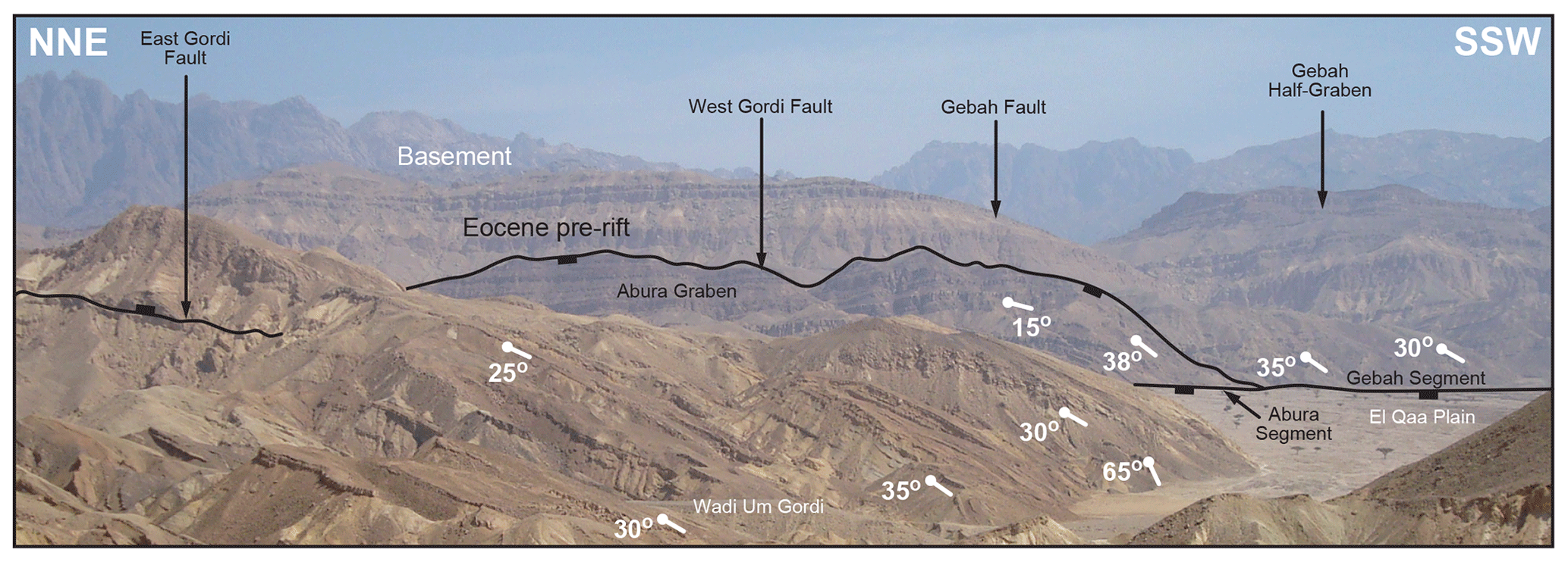
Figure 9Photograph looking ESE, along-strike of the Theghda Segment. The location of the photo location is shown in Fig. 8a.
2.3 Stratigraphic framework
The Suez Rift is underlain by Precambrian, “Pan-African” crystalline basement. The overlying sedimentary sequence is divided into three megasequences (Fig. 5). Megasequence 1 is ca. 500 m thick and composed of Cambrian to Lower Cretaceous clastics (Nubian Sandstone). This succession is conformably overlain by Mesozoic, mixed carbonate–clastic, and early Tertiary, carbonate-dominated rocks, which together comprise Megasequence 2 (ca. 650 m thick; Patton et al., 1994; Sharp et al., 2000). The competency contrast between mudstone-dominated intervals, such as the Duwi, Esna, and Darat formations, and carbonate- and sandstone-dominated units in the upper part of Megasequence 2 results in a strongly layered mechanical stratigraphy (Fig. 5); this exerts a strong control on the evolution of syn-rift structural styles, allowing decoupling and promoting extensional forced folding (sensu Coleman et al., 2019; see also Withjack et al., 1990; Sharp et al., 2000; Withjack and Callaway, 2000; Jackson et al., 2006; Wilson et al., 2009; Lewis et al., 2015). Megasequence 3 represents syn- to post-rift deposits associated with the formation of the Suez Rift. The lower, Oligo-Miocene, syn-rift part of Megasequence 3 consists of non-marine (Abu Zenima Formation; 24–21.5 Ma), tidal-to-marginal marine (Nukhul Formation; 21.5–19.7 Ma), and open marine (Rudeis Formation; 19.7–15.5 Ma) deposits (Gharandal Group) (Fig. 5). The upper, post-rift part of Megasequence 3 is composed of clastic, carbonate, and evaporite rocks (Ras Malaab Group) (e.g. Patton et al., 1994; Sharp et al., 2000). Due to a lack of hangingwall exposure, the full thickness of Megasequence 3 in the El-Qaa Fault Block is unknown. However, Lewis et al. (2015) demonstrate that Abu Zenima, Nukhul, and Rudeis formations are collectively at least 60 m thick.
2.4 Timing of deformation on the Hadahid Fault System
Although syn-rift growth strata are not preserved along its entire length, the following four observations by Lewis et al. (2015) place some constraints on the timing of deformation on the Hadahid Fault System: (i) early syn-rift strata of the Abu Zenima Formation (23.5–21 Ma; Fig. 5) onlap pre-rift strata (Mokattam Formation) along the Hadahid and East and West Feiran monoclines (Figs. 3a and 4g and i), suggesting that these structures initiated during the initial stages of rifting in the late Oligocene; (ii) early syn-rift strata of the Abu Zenima Formation (23.5–21 Ma; Fig. 5) are locally preserved in syn-depositional faults dissecting the Hadahid and East and West Feiran monoclines (not shown in the regional map in Fig. 3), suggesting that these faults, which Lewis et al. (2015) infer were kinematically linked to the forced folds on which they occur, initiated during the initial stages of rifting in the late Oligocene; (iii) late pre-rift (Eocene) strata of the Thebes Formation are thrust over early syn-rift (23.5–21 Ma) strata along the Ratamat Segment (see below), suggesting fold tightening and the deformation of the monocline middle limbs after rift initiation, perhaps during the early Miocene; and (iv) syn-rift depocentres of the Abura Graben and Gebah Half-Graben, which are located at the southern end of the Hadahid Fault System and that contain syn-rift strata as young as 16.9 Ma (i.e. Abu Zenima, Nukhul, and Rudeis formation; Fig. 5), are cross-cut by the Hadahid Fault System, implying that this structure was likely active post early Miocene (see Lewis et al., 2017).
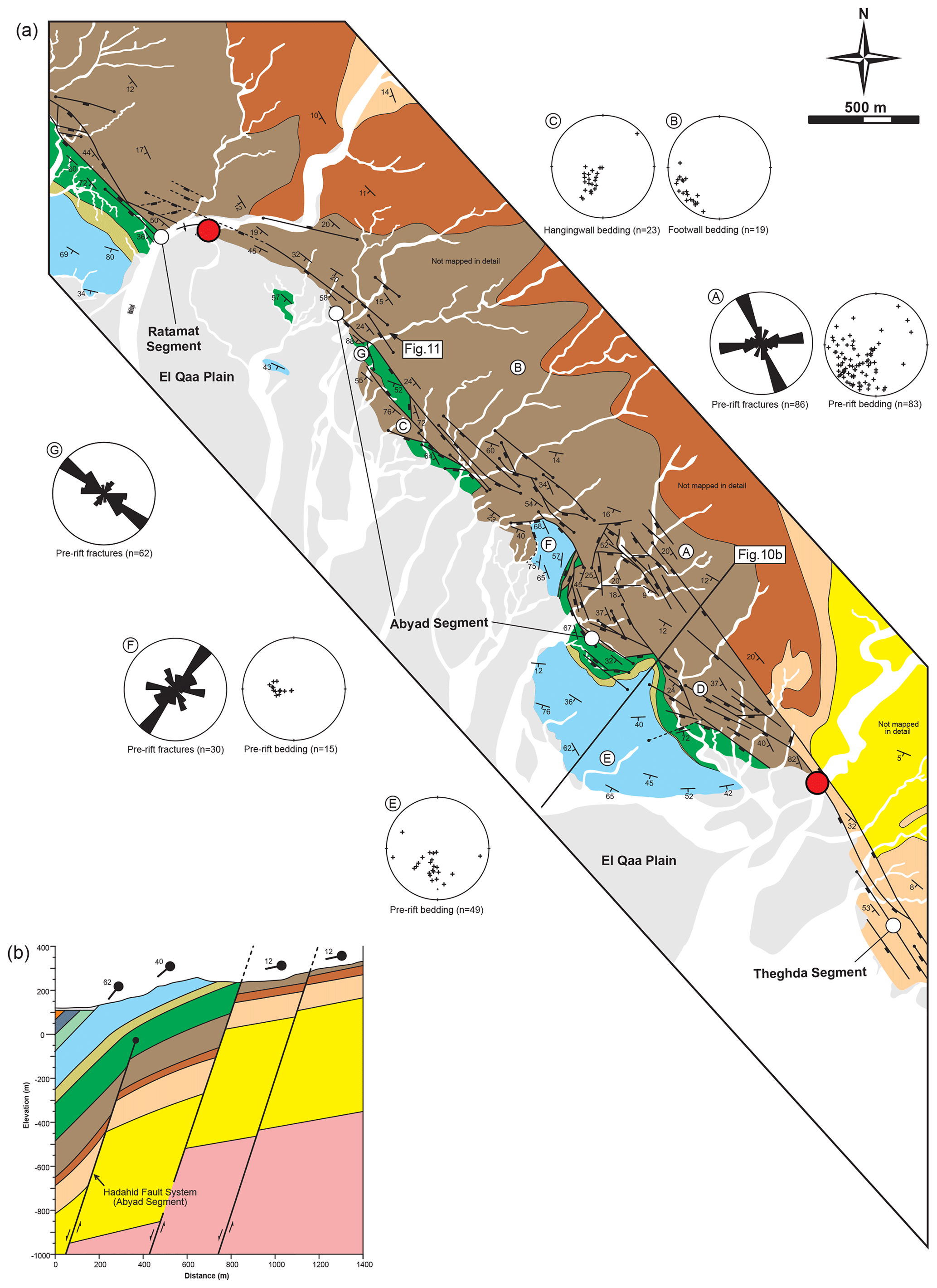
Figure 10(a) Field map of the Abyad Segment of the Hadahid Fault System. Colour key to stratigraphic units is shown in Fig. 3a. Red dots indicate the approximate boundaries between the identified segments. Lower-hemisphere projection stereonets summarize the dip and dip direction of pre- and syn-rift bedding (a–g; location shown on map). Rose diagrams show the trend of fractures in pre-rift strata on the middle limb of the Thebes Formation-cored monocline. The location of the photograph shown in Fig. 11 and the cross section shown in (b) are indicated. (b) Down-plunge cross section across the Abyad Segment.
We identify eight fault (i.e. Gebah and Abura, Hadahid Fault, Theghda, Abyad, and Ratamat fault segments) and three fold segments (i.e. Hadahid and the East and West Feiran monoclines) along the Hadahid Fault System, based on abrupt along-strike changes in fault strike and/or structural style, for example from a breached to an unbreached monocline (Fig. 3b) (see Stewart and Taylor, 1996). For much of its length, the hangingwall of the Hadahid Fault System is not exposed, being buried beneath thick Quaternary deposits of the El-Qaa Plain. In these locations we cannot therefore constrain the location of the master fault responsible for generating the bulk of the observable strain or the amount of displacement on the fault (Fig. 3a; see also Fig. 4a, b and d). For example, even where we observe a fault of appropriate scale (i.e. several hundreds of metres of throw), strike (e.g. ESE–WNW-to-SSE–NNW), and dip (i.e. broadly south-westwards), in broadly the correct structural position (i.e. immediately to the E or NE of the El-Qaa Plain), it remains unclear if this is the Hadahid Fault System “master fault”. However, we use the following criteria to help constrain the position of the master fault: (i) where reverse faults occur, these likely lie in the hangingwall of the master fault or on the hangingwall side of the up-dip projection of the master fault in cases where it is blind (see Fig. 1); and (ii) growth fold (monocline) breaching typically results in preservation of steeply dipping (or overturned) beds within the fault zone or in the immediate hangingwall of the fault; as a result of this, footwall bedding increases in dip towards the fault, and where bedding dips steeply (i.e. >70∘), the master fault is likely at or near the surface.
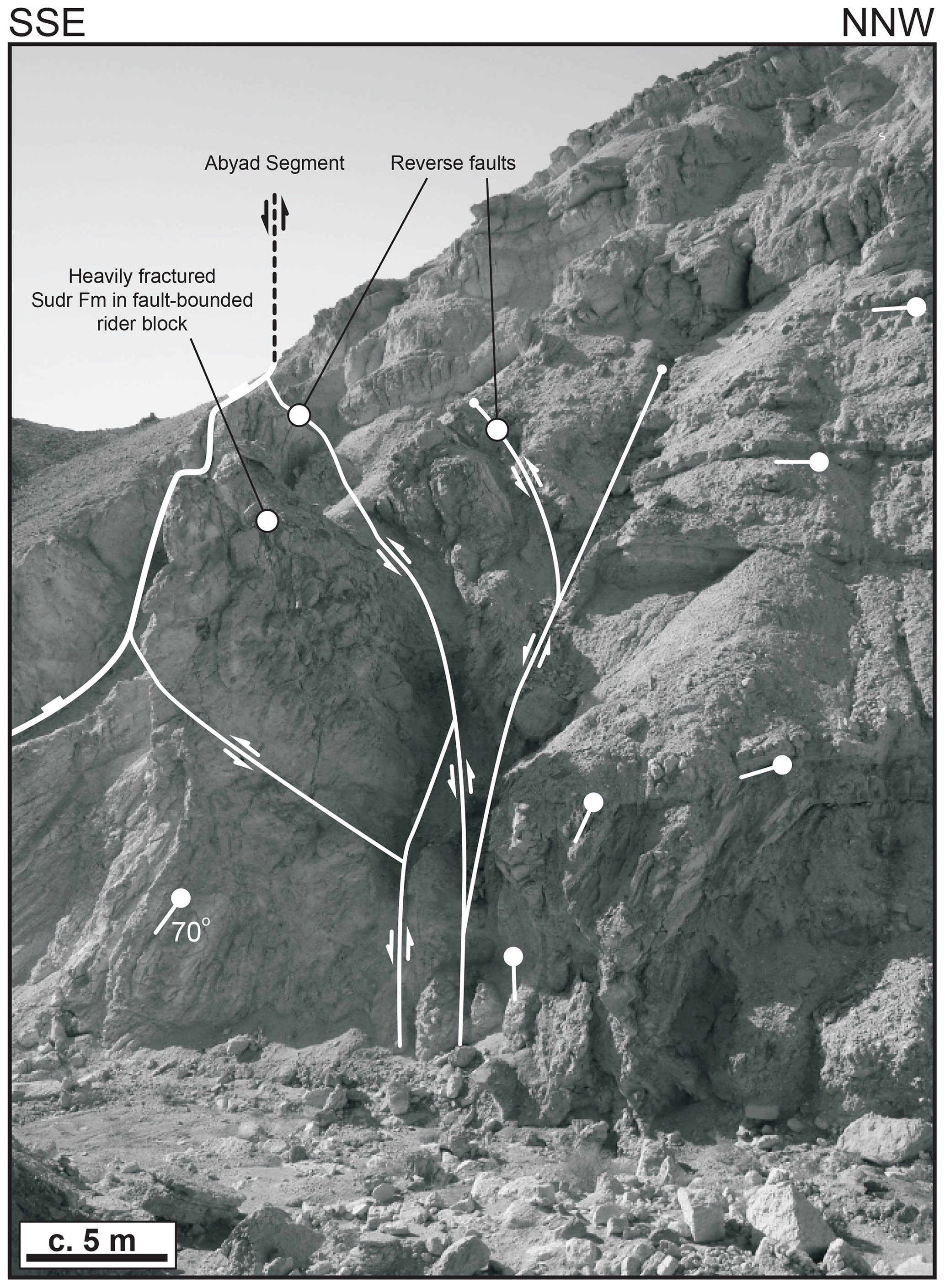
Figure 11Photograph showing the structure of a “secondary” normal fault zone associated with the Hadahid Fault System. The location of the photograph is shown in Fig. 10a.
Ignoring the fact that the position of the master fault is locally uncertain, the overall north-westward transition from breached to unbreached monoclines clearly defines a north-westward decrease in the ratio between discontinuous (i.e. fault offset-related) and continuous (i.e. fold-related), at-surface deformation (Figs. 3 and 4a–i). One hypothesis links this along-strike change in structural style to the north-westward propagation of the Hadahid Fault System from its branch line with the Gebah and Sinai Massif faults. In this model, extensional growth folds formed and were breached earlier in the SE than they were in the NW. The cessation of extension and the death of the Hadahid Fault System meant that unbreached extensional growth folds are preserved in the NW. We may refer to this along-strike in structural style as being a so-called “propagation effect”. An alternative hypothesis is that the Hadahid Fault System nucleated broadly synchronously along its length and then propagated upwards, more quickly in the SE, which ultimately leads to north-westward propagation of the fault system's surface trace. We may refer to this along-strike in structural style as being a so-called “geometric effect”. Differentiating between these two hypotheses is impossible given that (i) our structural level of inspection is restricted to the Earth's surface and thus we cannot demonstrate that fault-related displacement (i.e. discontinuous deformation) increases north-westwards at deeper structural levels (e.g. at the depth of top crystalline basement or top pre-rift; Fig. 5); and (ii) discontinuous exposures of very poorly dated syn-rift deposits in the hangingwall of the Hadahid Fault System mean we cannot establish the relative timing of faulting and folding along the structure; i.e. do the very earliest syn-rift growth strata become younger towards and thus document the north-westward initiation of folding and subsequent faulting and hence north-westward propagation of the fault system?
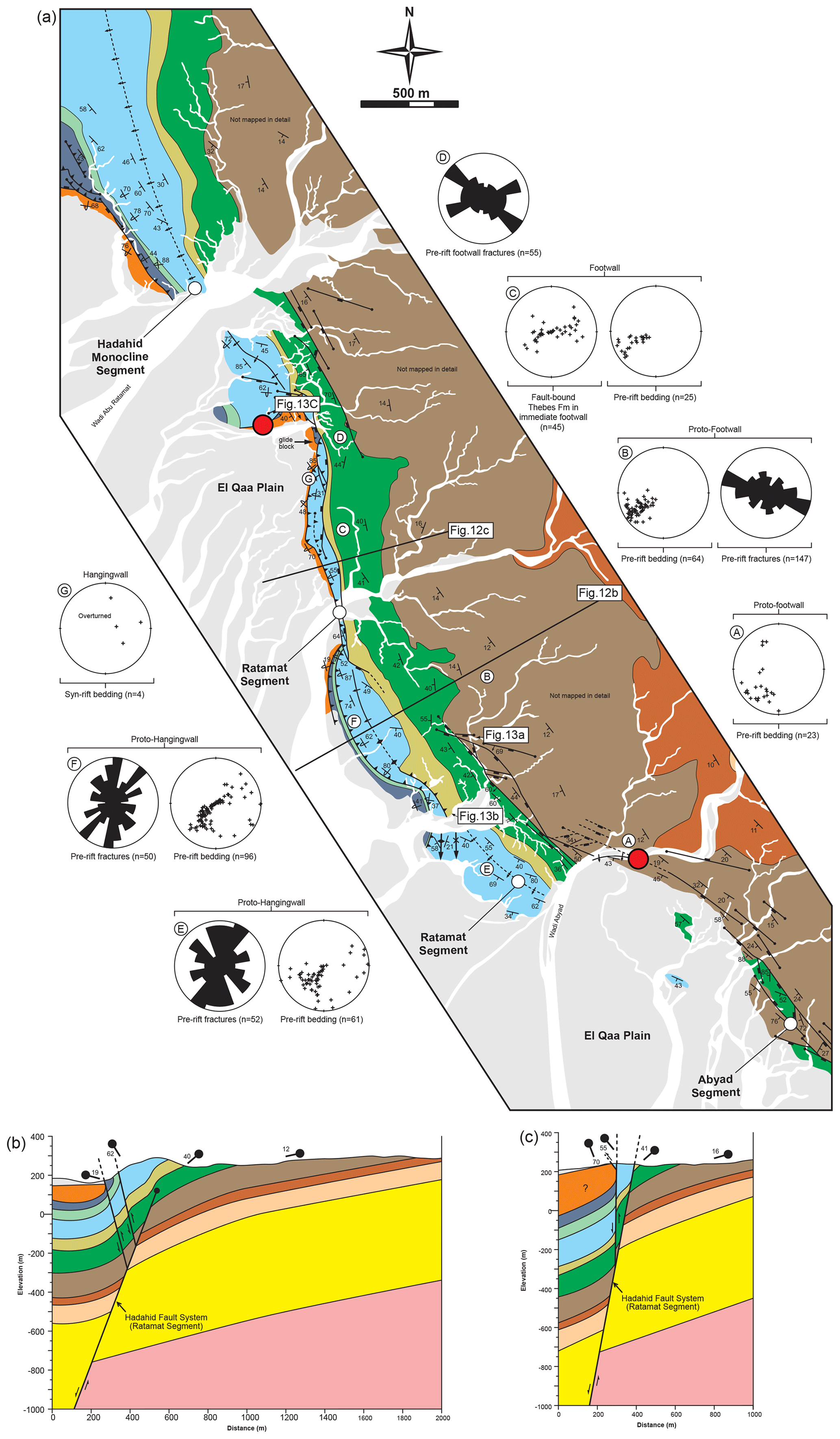
Figure 12(a) Field map of the Ratamat Segment of the Hadahid Fault System. Colour key to stratigraphic units is shown in Fig. 3a. Red dots indicate the approximate boundaries between the identified segments. Lower-hemisphere projection stereonets summarize the dip and dip direction of pre- and syn-rift bedding (a–g; location shown on map). Rose diagrams show the trend of fractures in pre-rift strata. The location of the photograph shown in Fig. 13 and the cross sections shown in (b) and (c) are indicated. (b) Down-plunge cross section across the central part of the Ratamat Segment. (c) Down-plunge cross section across the northern part of the Ratamat Segment.

Figure 13(a) Photograph showing the structure of a “secondary” normal fault zone associated with the Hadahid Fault System. (b) Photograph looking obliquely (to the NW) at the southern end of the Ratamat Segment of the Hadahid Fault System. The monocline limb is deformed by reverse faults which thrust older pre-rift over younger pre-rift strata (i.e. right-hand reverse fault) or pre- over syn-rift strata (i.e. left-hand reverse fault). (c) Photograph looking obliquely (to the S) at the northern end of the Ratamat Segment. The Hadahid Fault System master fault is surface-breaching and is inferred to lie to the east of the network of reverse faults that dissected the strongly rotated middle limb of a precursor monocline. The reverse fault-bound block of pre-rift Thebes Formation is thrust onto overturned syn-rift strata. Locations of the photos are shown in Fig. 12a.
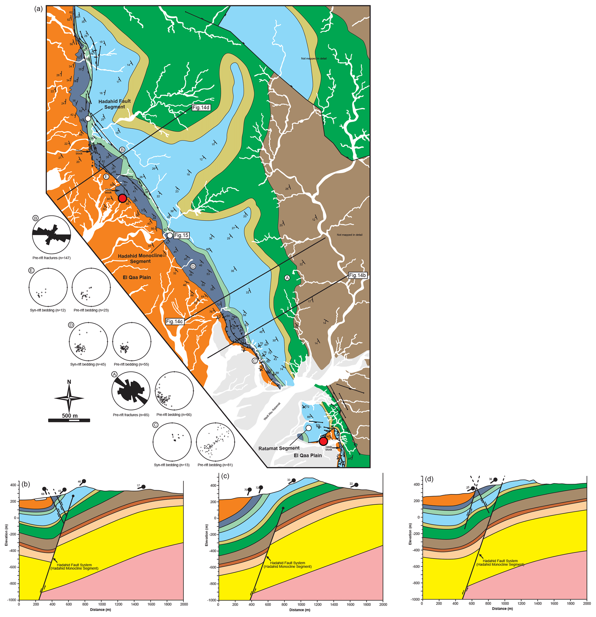
Figure 14(a) Field map of the Hadahid Monocline and Hadahid fault (see also Fig. 16) segments of the Hadahid Fault System. Colour key to stratigraphic units is shown in Fig. 3a. Red dots indicate the approximate boundaries between the identified segments. Lower-hemisphere projection stereonets summarize the dip and dip direction of pre- and syn-rift bedding (a–g; location shown on map). Rose diagrams show the trend of fractures in pre-rift strata. The location of the photograph shown in Fig. 15 and the cross sections shown in (b) and (c) are indicated. (b) Down-plunge cross section across the central part of the Hadahid Monocline Segment. (c) Down-plunge cross section across the south-central part of the Hadahid Monocline Segment. (d) Down-plunge cross section across the southern part of the Hadahid Fault Segment.

Figure 15Photograph looking northwards along the Hadahid Monocline Segment. Note the angular discordance of ca. 10∘ between the pre-rift (Mokattam Formation) and overlying syn-rift strata (Nukhul Formation) (see Lewis et al., 2015). Location of the photo is shown in Fig. 14a.
In this section we describe and interpret the structural style (i.e. plan-view and cross-sectional geometry) of the eight fault–fold segments of the Hadahid Fault System from south to north, following the inferred direction of displacement decrease along the structure. Where we infer the displacement of the master fault, it should be noted these values are based on stratigraphic cut-offs and do not include the ductile component of deformation (e.g. folding); displacement values are, therefore, minimum estimates of extensional strain (e.g. Walsh and Watterson, 1991).
3.1 Gebah Segment
The Gebah Segment is located at the southern end of the Hadahid Fault System and is defined by NNW–SSE-to-WNW–ESE-striking, W–SW-to-W-dipping, ca. 3.5 km long normal fault (Figs. 3b, 6a and b). This segment splays off the Eastern Boundary Fault Belt, at the branch point between the Gebah and Sinai Massif segments (Figs. 3b, 6a and 7). Along much of its length the immediate footwall of the Gebah Segment is defined by a ca. 500 m wide anticline that is deformed by numerous normal faults (Figs. 6a and 7). NE of this anticline, a 1–1.5 km wide, N-trending syn-rift half-graben is developed, which is bound on its eastern margin by the Eastern Boundary Fault Belt (Gebah Half-Graben; Figs. 5a, 6 and 7; Lewis et al., 2015).
Based on (i) the sharp increase in topographic relief along the north-eastern margin of the El-Qaa Plain at its contact with exposed pre- and syn-rift rocks and (ii) the presence of faulted and folded syn-rift strata in the Gebah Half-Graben, we infer that the master fault of the Hadahid Fault System is surface-breaching along the Gebah Segment. As such, we interpret the anticline characters of the footwall of the Gebah Segment as representing the footwall portion of a breached monocline; the related hangingwall syncline is buried beneath the El-Qaa Plain (cf. Fig. 1). Because of this, we cannot constrain the displacement along this part of the Hadahid Fault System (Fig. 6a and b).
3.2 Abura Segment
The Abura Segment is defined by a WNW–ESE-striking, SW-dipping, ca. 2 km long normal fault (Fig. 6a and c). The structural style of the Abura segment is similar to that of the Gebah Segment, with syn-rift strata in its footwall defining a faulted footwall anticline. Because of this structural similarity, we also interpret the Abura Segment defining a breached monocline, with the hangingwall syncline buried beneath the El-Qaa Plain (Fig. 6a and b). Again, because of this, we cannot constrain the displacement along this part of the Hadahid Fault System (Fig. 6a and c).
3.3 Theghda Segment
The Theghda Segment is ca. 4.5 long, trends WNW to NW, and is defined by strata that dip SSW (along its southern part) or WSW (northern part), and which define a ca. 1.5 km wide anticline (Figs. 8a and 9). Dominantly WSW–ESE-to-NW–SE-striking, SSW-to-SW-dipping, moderate-throw (up to 100 m) normal faults are locally developed along the Theghda Segment.

Figure 16(a) Field map of the Hadahid Fault Segment of the Hadahid Fault System. Colour key to stratigraphic units is shown in Fig. 3a. Red dots indicate the approximate boundaries between the identified segments. Lower-hemisphere projection stereonets summarize the dip and dip direction of pre- and syn-rift bedding (a–g; location shown on map). Rose diagrams show the trend of fractures in pre-rift strata. The location of the photograph shown in Fig. 17 and the cross sections shown in (b) are indicated. (b) Down-plunge cross section across the central part of the Hadahid Fault Segment.
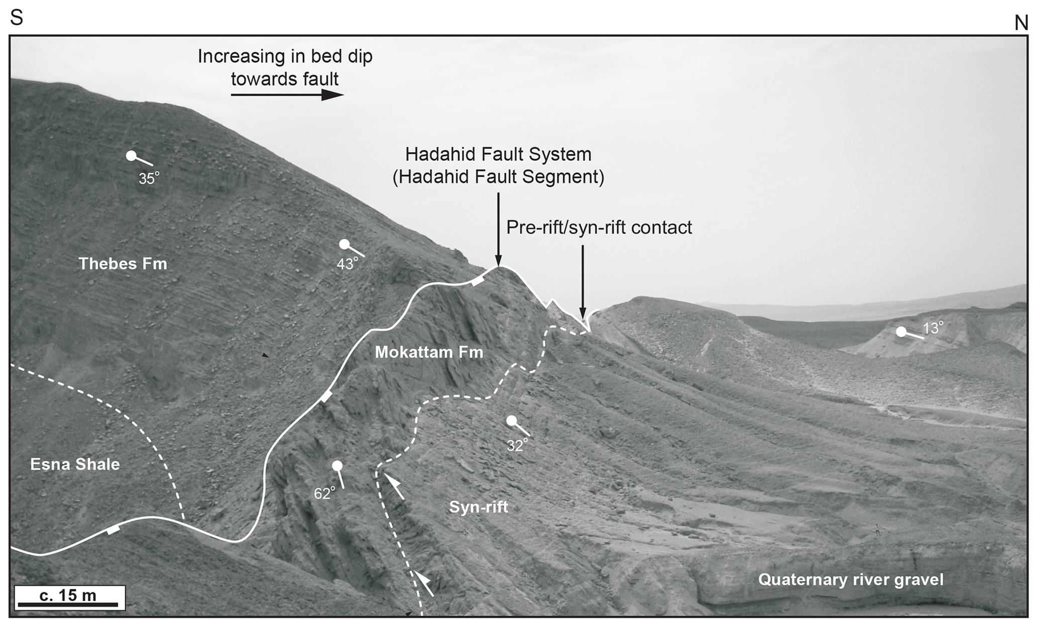
Figure 17Photograph looking westwards along the Hadahid Fault Segment. Note the angular discordance of ca. 10∘ between the pre-rift (Mokattam Formation) and overlying syn-rift strata (Nukhul Formation) (see Lewis et al., 2015). Location of the photo is shown in Fig. 16a.
Based on outcrop relationships and exposure levels, there are three possible interpretations for the location of the Hadahid Fault System master fault along the Theghda Segment. First, the master fault may be represented by the normal faults mapped to the NNE of the monocline middle limb. In this interpretation, Eocene strata exposed along the southern part of the segment lie in the fault's hangingwall and are eroded and thus absent further NW, whereas Cretaceous strata along the northern part of the segment lie in its footwall (Fig. 8b). Second, the master fault could be blind, underlying the monocline middle limb (i.e. the interpretation shown in Figs. 4c and 8b). Finally, the master fault could lie SSW of the main outcrop belt, beneath the El-Qaa Plain; in this interpretation, Eocene and Cretaceous strata lie in the fault's footwall, with Eocene strata absent along the northern part of the segment due to erosion (interpretation not shown). In all three interpretations the eastern part of the master fault would lie directly along-strike of where we map it along the Abura Segment (Fig. 8a). Given that stratal dips increase towards and are at a maximum immediately adjacent to the El-Qaa Plain (Fig. 8b), we reject the first interpretation, as this would require a progressive decrease in stratal dips SSW of the faults juxtaposing Eocene and Cretaceous strata (Fig. 8). We therefore favour the second or third interpretation; the former suggests an along-strike decrease in displacement on the fault, such that its tip plunges towards and is blind in the WNW, whereas the latter envisages that the fault is surface-breaking (but just not observable).
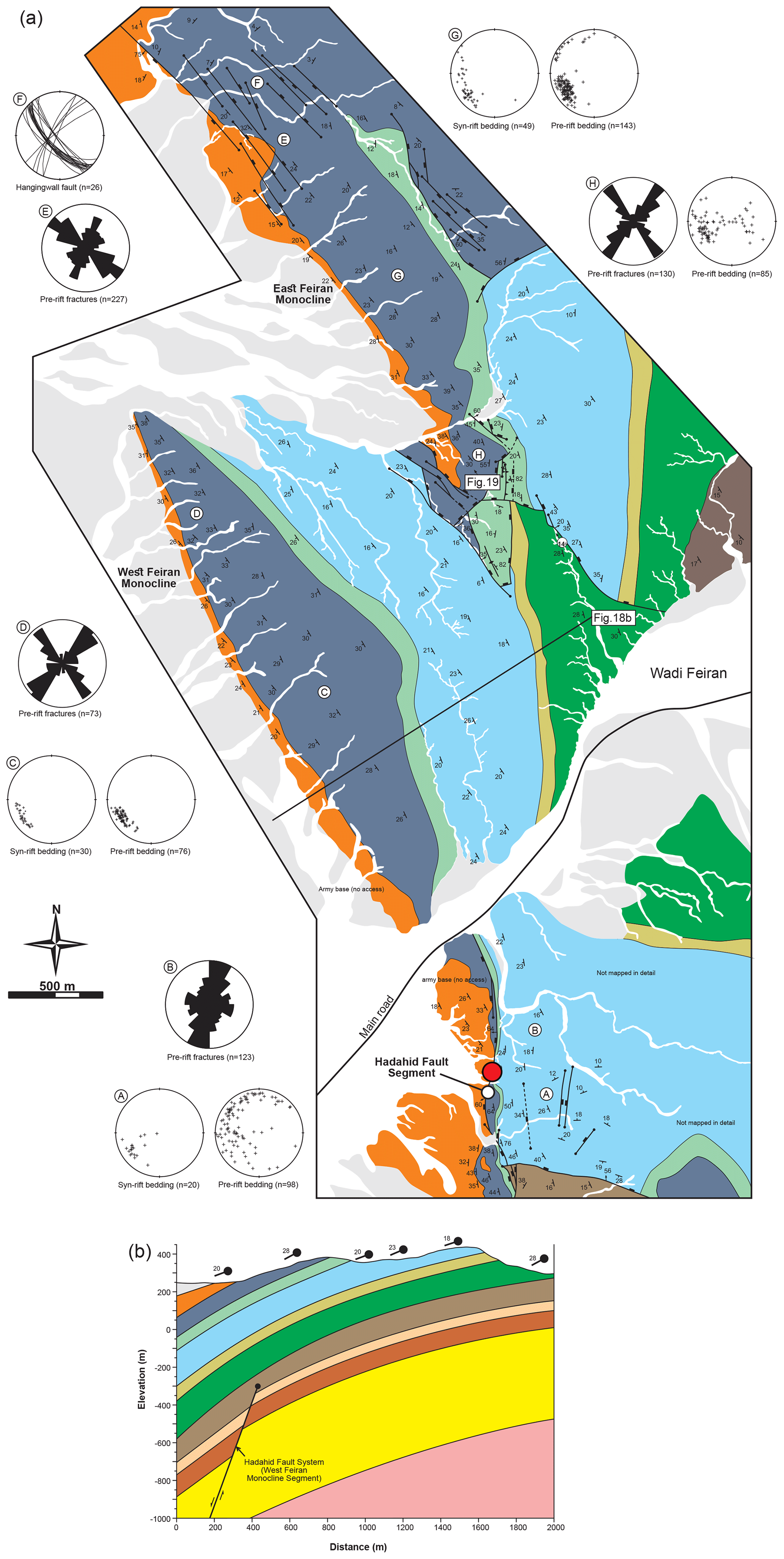
Figure 18(a) Field map of the Feiran monoclines segment of the Hadahid Fault System. Colour key to stratigraphic units is shown in Fig. 3a. Red dots indicate the approximate boundaries between the identified segments. Lower-hemisphere projection stereonets summarize the dip and dip direction of pre- and syn-rift bedding (a–g; location shown on map). Rose diagrams show the trend of fractures in pre-rift strata. The location of the photograph shown in Fig. 19 and the cross sections shown in (b) are indicated. (b) Down-plunge cross section across the West Feiran Monocline.

Figure 19Photograph looking northwards along the middle limb of the East Feiran Monocline Segment. Location of the photo is shown in Fig. 18.
3.4 Abyad Segment
The Abyad Segment has a similar overall structural style and is of similar scale to that of the adjacent Theghda Segment, being ca. 4 km long and trending NW and characterized by SW-dipping strata that define an up to ca. 1 km wide anticline (Fig. 10). Numerous NW–SE-striking, predominantly SW-dipping, low-throw (up to 50 m) normal faults are present along the Abyad Segment, defining an up to ca. 500 m wide zone of intense deformation. These faults bound rotated blocks of the Matulla Formation, within which mudstones layers are highly attenuated (Fig. 11a). Within the fault zone, 5–30 m wide, fault-bounded blocks of intensely fractured Sudr Chalk occur (Fig. 14).
We again suggest that there are three possible interpretations for the position of the master fault in this location. For reasons outlined above, we again favour an interpretation that (i) the master fault is blind, underlying the monocline middle limb (i.e. the interpretation shown in Fig. 10b); in this interpretation, the zone of relatively low-throw normal faults could represent the upper tip of the master fault, which in this case would lie just below the level of exposure (see Fig. 1b); or (ii) the master fault is surface-breaking, but lies SSW of the main outcrop belt, beneath the El-Qaa Plain.
3.5 Ratamat Segment
The ca. 3 km long, NNW-to-N-trending Ratamat Segment displays a broadly similar geometry to the Abyad and Theghda segments, being defined by SW-to-W-dipping strata that define a ca. 1 km wide anticline that is deformed by low-throw normal faults towards its southern end (Fig. 12a and b). These faults bound blocks of the Matulla Formation, within which mudstone layers are highly attenuated (Fig. 13a). Heavily fractured blocks of Sudr Chalk are also present between closely spaced faults. The Ratamat Segment differs from the Abyad and Theghda segments in that reverse faults are well-developed along its central and northern parts. Along its central part, a NNW–SSE-striking thrust places steep to locally overturned Thebes Formation carbonates on top of overturned, mixed carbonate–clastics of the Darat and Mokattam formations (Figs. 12a and b and 13b). Further north, two E-dipping, N–S-striking, ca. 1 km long thrusts occur, placing overturned pre-rift strata onto steep-dipping to overturned syn-rift strata (Figs. 12a and c and 13c).
Observations from numerical and physical models (Fig. 1a and b) and from other natural examples of extensional growth folds (e.g. Sharp et al., 2000; Jackson et al., 2006; Coleman et al., 2019) (see also Fig. 1c) suggest that the reverse faults lie in the immediate hangingwall of the master fault. As such, we interpret that the Hadahid Fault System master fault lies east of these reverse faults (interpretation shown in Fig. 12). Locally, however, the master fault may be blind, as suggested by the intact monocline defining the middle of the Ratamat Segment. Even here, reverse faults locally offset the monocline limb, suggesting the upper tip of the master fault is near-surface (interpretation shown in Fig. 12b; see also Fig. 1a).
3.6 Hadahid Monocline
The Hadahid Monocline is a 5 km long, NW–SE-striking, SW-facing, unbreached monocline, the middle limb of which increase in dip from NW to SE (from 40∘ to locally overturned) (Fig. 14). Overall, the dip of the monoclines middle limb (<65∘) immediately adjacent to the El-Qaa Plain is less than that observed on segments to the SE. In the SE, where the monocline middle limb dips more steeply (>65∘), several NW–SE-striking, moderately (30–50∘) NE-dipping reverse faults place steeply dipping to locally overturned pre-rift strata on overturned syn-rift strata (Fig. 14a and b). These structures are geometrically similar to those observed along the Ratamat Segment, suggesting that, like the central part of that structure, the upper tip of the master fault is near-surface and is, at its southern end at least, represented by the zone of at-surface, relatively low-throw normal faults described above. Immediately to the NW of the zone of reverse faults, where it dips more gently, the monocline middle limb is undeformed; further to the NW, where it passes into the Hadahid Fault Segment, normal faults become more common (see below) (Fig. 14a and c). Along the entire length of the Hadahid Monocline, syn-rift sandstones onlap pre-rift carbonates across a low-angle, angular unconformity (ca. 10∘ angular discordance) (Figs. 14a and c, 15 and 17) (see Lewis et al., 2015).
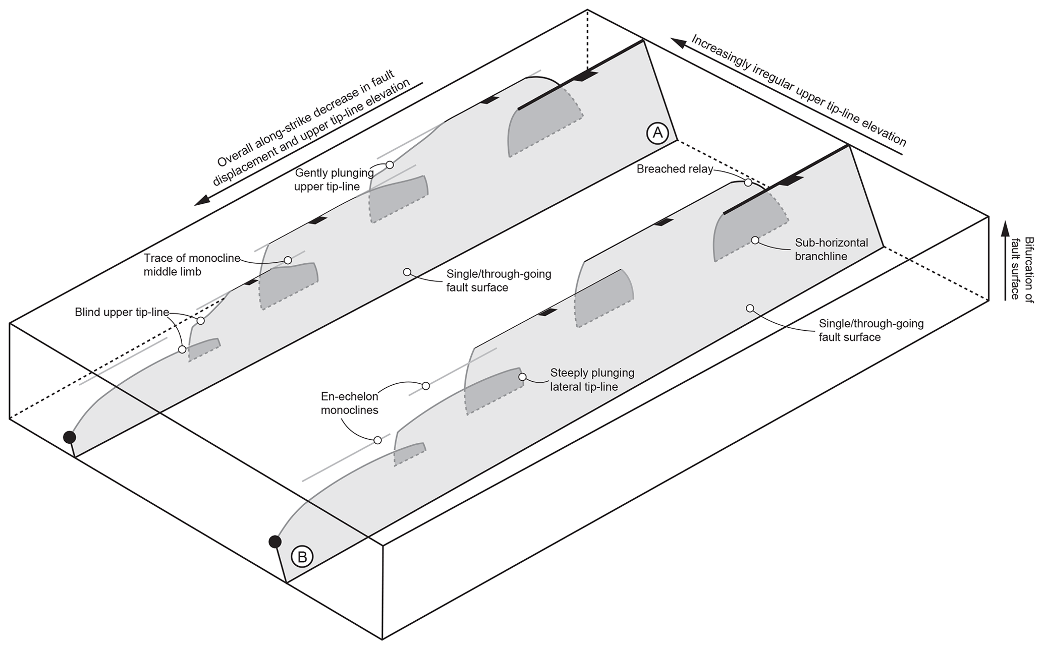
Figure 20Schematic diagram summarizing some of the key observations from the Hadahid Fault System and outlining key structural elements of segmented normal fault–fault propagation fold systems. Fault A is defined by an irregular upper tip-line elevation, superimposed on a net right-to-left decrease in elevation and net fault displacement (i.e. the Hadahid Fault System); Fault B is defined by an more smoothly decreasingly fault displacement and elevation of the upper tip line. Footwall-anticline–hangingwall-syncline pairs, which represent breached fault-propagation folds (monoclines) and that flank the breaching faults, are not shown for clarity.
3.7 Hadahid Fault Segment
The Hadahid Fault Segment is ca. 5.5 km long, strikes N–S, and is defined by a breached, W-facing monocline (Figs. 16 and 17) that is deformed by several N–S-to-NW-SE-striking, steeply (70–80∘) and broadly W-dipping, 0.5–2 km long normal faults that have a maximum throw of ca. 300 m (Figs. 16 and 17). The Hadahid Fault Segment is one of the few places where the hangingwall of the Hadahid Fault System is relatively well exposed; here we see relatively steeply (ca. 60∘) W-dipping strata at the segment centre, with these pre-rift strata onlapped by syn-rift strata across a low-angle (ca. 10∘ angular discordance) unconformity (Figs. 16 and 17). We infer the Hadahid Fault Segment is represented by the faults that breach the related monocline east of the position where syn-rift strata onlap it. Accordingly, we interpret this monocline is a breached extensional growth fold (Figs. 16 and 17; cf. Fig. 1a and c).
3.8 Feiran monoclines
The Feiran monoclines are represented by two NW–SE-striking, SW-facing, up to 4.5 km monoclines that overlap by ca. 1.75 km and are separated across-strike by 1–5 km (the West Feiran and East Feiran monoclines; Figs. 2, 3, 18, and 19). The West Feiran Monocline plunges north-westwards and is breached at its southern end by a steeply (ca. 70∘) SW-dipping fault that tips out just north of Wadi Feiran; this fault represents the northern end of the Hadahid Fault Segment (Fig. 18a). The East Feiran Monocline also plunges to the NW, with stratal dips on the middle limb decreasing along-strike from ca. 35∘ to ca. 10∘ WSW (Fig. 18a). Variably striking, relatively small (up to 1.2 km long and with up to 60 m displacement) normal faults deform the monocline middle limb (Fig. 18a). Pre-rift rocks defining the East and West Feiran monoclines are onlapped by syn-rift deposits across an angular unconformity defined by a 5–10∘ dip discordance (Figs. 18 and 19) (see Lewis et al., 2015).
Current geometrical models for extensional growth folds predict a relatively smooth, along-strike transition from a breached monocline to an unbreached monocline, the latter being developed above the smoothly plunging, upper tip line of the underlying (and laterally related) normal fault (e.g. Gawthorpe et al., 1997; Gawthorpe and Leeder, 2000; Cardozo, 2008; Coleman et al., 2019). The Hadahid Fault System displays many of the geometrical characteristics captured in this model. For example, the inferred north-westward decrease in bulk displacement on the fault system is associated with an overall change in structural style, from breached monoclines in the SE (e.g. Gebah Segment) to unbreached monoclines in the NW (e.g. Feiran monoclines). However, we show that, in detail, the along-strike transition in structural style is more discontinuous, with unbreached monoclines (i.e. Hadahid Monocline) being flanked by breached or unbreached monoclines (i.e. Ratamat and Hadahid segments) (Figs. 3 and 14). Individual segments of the Hadahid Fault System are also flanked (and defined) by segment boundaries that are (i) unbreached at the structural level of exposure (e.g. between the West and East Feiran monoclines; Figs. 3 and 18); (ii) breached and defined by a pronounced bend in the fault–fold trace (e.g. between the Hadahid Monocline and Ratamat segments; Figs. 3 and 14; and between the Ratamat and Abyad segment; Figs. 3 and 12); or (iii) are defined by a more subtle transition in overall structural style (e.g. between the Theghda and Abyad segments; Figs. 3 and 10). Unbreached segment boundaries are characterized by relatively small (ca. 2 km) across-strike separations and large (ca. 3 km) along-strike overlaps; these segments are thus defined by high overlap : separation (O : S) ratios (sensu Whipp et al., 2017) (Figs. 3 and 18). In the case of breached segment boundaries, the strike-normal step in the fault's plan-view trace is similarly small (i.e. maximum 500 m) relative to the length of the bounding segments (typically at least 4 km) (Figs. 3, 10 and 12). We tentatively suggest that the high O : S ratios between unlinked segments of the Hadahid Fault System, as well as the narrow width of breached relays, together suggest the structure is defined by a single, hard-linked structure at depth, which splays upwards into and is thus defined by several segments at shallower depths (Fig. 20). Similar geometries are observed in 3D seismic reflection data from the Taranaki Basin, offshore of New Zealand, where Conneally et al. (2017) describe segmented fault–fold systems, separated by relays at relatively shallow structural depths, above and related to upward progradation of a single, ca. 8 km long basement-involved normal fault (i.e. their Fig. 8).
Where data quality and quantity permit three-dimensional mapping of extensional growth folds and causal faults (e.g. Corfield and Sharp, 2000; Ford et al., 2007), the relatively short length-scale (<5 km) variations in structural style we described from the central part of the Hadahid Fault System are absent. The reason for this is unclear and may reflect the fact that the Hadahid Fault System was associated with non-uniform upward propagation of its upper tip, superimposed on the overall north-westward propagation of the fault. Non-uniform propagation could be controlled by short length-scale variations in the mechanical properties of the faulted host rock and associated changes in the propagation-to-slip ratio (Hardy and McClay, 1999; Finch et al., 2004; Hardy and Finch, 2006). A consequence of this would be that, above portions of the fault tip that were propagating relatively rapidly, monoclines would be breached, with intact monoclines being preserved along-strike in locations where, at least locally, tip propagation was relatively slow. Such variability may therefore be absent in subsurface examples due to (i) seismic data resolution being insufficient to resolve relatively low-displacement structures that locally breach seemingly unbreached monoclines (e.g. Lewis et al., 2013) and/or (ii) the faulted and folded host rock being relatively lithologically and thus mechanically homogeneous. For example, in the Taranaki Basin example of Conneally et al. (2017), the fault grew in a relatively homogenous, mudstone-dominated succession. Irrespective of what controls the short length-scale structural variability seen along the Hadahid Fault System, our study supports the notion that including the ductile component of deformation (i.e. folding) is key when defining the geometry and assessing the kinematics of segmented normal fault systems (e.g. Walsh and Watterson, 1991).
Where unbreached monoclines are preserved, or where the steep-dipping limbs of breached monoclines are exposed in the fault system hangingwall, most commonly towards the centre of the Hadahid Fault System, reverse faults are relatively well-developed. It is likely these structures are not developed to the NW due to the lower total bulk strains (i.e. faulting and folding); to the SE, these structures may be developed, but are simply not exposed, being buried beneath hangingwall strata due to higher strains and, therefore, larger discrete, fault-related displacements. Thrusts are rarely described from seismic reflection datasets but are common in exposed forced folds in the Suez Rift (Withjack et al., 1990; Gawthorpe et al., 1997; Sharp et al., 2000; Jackson et al., 2006). The apparent lack of thrusts in seismic reflection datasets may simply reflect the fact that many thrusts have low displacements (<100 m), are steeply dipping (>50∘), and are thus unlikely to be imaged in seismic reflection datasets (although see Fig. 1c for an exception).
We used field data from the Hadahid Fault System, Suez Rift, Egypt, to investigate the geometry and kinematic development of an exceptionally well-exposed normal fault system. We showed that this 30 km long fault system, which has up to 2.5 km of displacement, comprises eight up to 5 km long segments that are defined by unbreached or breached, hard- or soft-linked monoclines. The high overlap : separation (O : S) ratios between the constituent segments of the Hadahid Fault System suggest it passes upwards from a single, through-going structure at depth, into a more strongly segmented feature at shallower depths. We infer that the along-strike transition from breached to unbreached monoclines records a progressive loss of displacement along the Hadahid Fault System at deeper structural levels and may suggest that the surface trace of the fault propagated north-westwards. We document short (<4 km) length-scale variations from unbreached to breached monoclines, which may reflect variations in the fault propagation-to-slip ratio, and the timing and location of growth fold breaching, perhaps linked to local variations in host rock material properties. We conclude that growth folding is a key expression of continental rift-related strain and that tectono-sedimentary models for rift basin development must incorporate related structures.
Data are not publicly available. Data are available upon request from the lead authors (c.jackson@imperial.ac.uk or rockbotherer1977@gmail.com).
CALJ and RLG devised the study. PSW, CALJ, RLG, and MML contributed to the collection and analysis of field data. CALJ and PSW prepared the manuscript, with RLG and MML contributing to manuscript editing.
The authors declare that they have no conflict of interest.
We thank Stefano Tavani and John Conneally for constructive reviews that helped improve the initial version of this paper. We also thanks journal editor Federico Rossetti and numerous Copernicus staff for editorial handling and assistance with paper production. The authors extend their thanks to Paul Wilson, Ian Sharp, and Nestor Cardozo for insightful discussions in the field. Adel Moustafa is acknowledged for his regional structural mapping in the Suez Rift, which provided an excellent starting point for this work. Wind Sand Stars, UK, and Abanoub Travel, Egypt, are thanked for their logistical support throughout the fieldwork programme.
Financial support for this study was provided by an Engineering and Physical Sciences Research Council (EPSRC) bursary and Statoil ASA (now Equinor ASA) via Natural Environmental Research Council (NERC) facilitated CASE Funding. Additional support was provided by the Central London Research Fund, an Elspeth Matthews Grant from the Geological Society of London, and an award from the AAPG Grants-in-Aid scheme.
This paper was edited by Federico Rossetti and reviewed by John Conneally and Stefano Tavani.
Allmendinger, R. W.: Inverse and forward numerical modeling of trishear fault-propagation folds, Tectonics, 17, 640–656, https://doi.org/10.1029/98TC01907, 1998.
Baudon, C. and Cartwright, J.: The kinematics of reactivation of normal faults using high resolution throw mapping, J. Struct. Geol., 30, 1072–1084, https://doi.org/10.1016/j.jsg.2008.04.008, 2008.
Bell, R. E., Jackson, C. A.-L., Whipp, P. S. and Clements, B.: Strain migration during multiphase extension: Observations from the northern North Sea, Tectonics, 33, 1936–1963, https://doi.org/10.1002/2014TC003551, 2014.
Bentham, P. A., Wescott, W. A., Krebs, W. H., and Lund, S. P.: Magnetostratigraphic correlation and dating of the early to middle Miocene within the Suez rift, AAPG Bull., 79, 1197–1198, 1996.
Bosworth, W.: A high-strain rift model for the southern Gulf of Suez (Egypt), in: Hydrocarbon Habitat in Rift Basins, edited by: Lambiase, J. J., Geol. Soc. Lond. Spec. Publ., 80, 75–102, https://doi.org/10.1144/GSL.SP.1995.080.01.04, 1995.
Bosworth, W. and McClay, K.: Structural and stratigraphic evolution of the Gulf of Suez rift, Egypt: A synthesis, in: Peri-Tethys Memoir 6: Peri-Tethyan Rift/Wrench Basins and Passive Margins, edited by: Ziegler, P. A., Cavazza, W., Robertson, A. H. F., Crasquin-Soleau, S., Mémoirs du Muséum National d'Historie Naturelle de Paris, 567–606, 2001.
Cardozo, N.: Trishear in 3D. Algorithms, implementation, and limitations, J. Struct. Geol., 30, 327–340, https://doi.org/10.1016/j.jsg.2007.12.003, 2008.
Camanni, G., Roche, V., Childs, C., Manzocchi, T., Walsh, J., Conneally, J., Saqab, M. M., and Delogkos, E.: The three-dimensional geometry of relay zones within segmented normal faults, J. Struct. Geol., 129, 103895, https://doi.org/10.1016/j.jsg.2019.103895, 2019.
Childs, C., Nicol, A., Walsh, J. J., and Watterson, J.: The growth and propagation of synsedimentary faults, J. Struct. Geol., 25, 633–648, https://doi.org/10.1016/S0191-8141(02)00054-8, 2003.
Childs, C., Holdsworth, R. E., Jackson, C. A.-L., Manzocchi, T., Walsh, J. J., and Yielding, G.: Introduction to the geometry and growth of normal faults, in: The geometry and growth of normal faults, edited by: Childs, C., Holdsworth, R. E., Jackson, C. A.-L., Manzocchi, T., Walsh, J. J., and Yielding, G., Geol. Soc. Lond. Spec. Publ., 439, 1–9, https://doi.org/10.1144/SP439.24, 2017.
Coleman, A. J., Duffy, O. B., and Jackson, C. A.-L.: Growth folds above propagating normal faults, Earth-Sci. Rev., 102885, https://doi.org/10.1016/j.earscirev.2019.102885, 2019.
Colletta, B., Le Quellec, P., Letouzy, J., and Moretti, I.: Longitudinal evolution of the Suez Rift structure (Egypt), Tectonophysics, 153, 221–233, https://doi.org/10.1016/0040-1951(88)90017-0, 1988.
Conneally, J., Childs, C., and Nicol, A.: Monocline formation during growth of segmented faults in the Taranaki Basin, offshore New Zealand, Tectonophysics, 721, 310–321, https://doi.org/10.1016/j.tecto.2017.06.036, 2017.
Corfield, S. C. and Sharp, I. R.: Structural style and stratigraphic architecture of fault-propagation folding in extensional settings: a seismic example from the Smørbukk area, Halten Terrace, Mid-Norway, Basin Res., 12, 329–341, https://doi.org/10.1111/j.1365-2117.2000.00133.x, 2000.
Deckers, J.: Decoupled extensional faulting and forced folding in the southern part of the Roer Valley Graben, Belgium, J. Struct. Geol., 81, 125–134, https://doi.org/10.1016/j.jsg.2015.08.007, 2015.
El-Wahed, M. A., Ashmawy, M., and Tawfik, H.: Structural setting of Cretaceous pull-apart basins and Miocene extensional folds in the Quseir-Umm Gheig region, northwestern Red Sea, Egypt, Lithosphere-US, 2, 13–32, https://doi.org/10.1130/L27.1, 2010.
Ferrill, D. A. and Morris, A. P.: Fault zone deformation controlled by carbonate mechanical stratigraphy, Balcones fault system, Texas, AAPG Bull., 92, 359–380, https://doi.org/10.1306/10290707066, 2008.
Ferrill, D. A., Morris, A. P., and Smart, K. J.: Stratigraphic control on extensional fault propagation folding: Big Brushy Canyon monocline, Sierra del Carmen, Texas, in: Structurally complex reservoirs, edited by: Jolley, S. J., Barr, D., Walsh, J. J., and Knipe, R. J., Geol. Soc. Lond. Spec. Publ., 292, 203–217, https://doi.org/10.1144/SP292.12, 2007.
Ferrill, D. A., Morris, A. P., and McGinnis, R. N.: Extensional fault-propagation folding in mechanically layered rocks: The case against the frictional drag mechanism, Tectonophysics, 576, 78–85, https://doi.org/10.1016/j.tecto.2012.05.023, 2012.
Finch, E., Hardy, S., and Gawthorpe, R.: Discrete-element modelling of extensional fault-propagation folding above rigid basement fault blocks, Basin Res., 16, 467–488, https://doi.org/10.1111/j.1365-2117.2004.00241.x, 2004.
Ford, M., Le Carlier de Veslud, C., and Bourgeois, O.: Kinematic and geometric analysis of fault-related folds in a rift-setting: The Dannemarie basin, Upper Rhine Graben, France, J. Struct. Geol., 29, 1811–1830, https://doi.org/10.1016/j.jsg.2007.08.001, 2007.
Fossen, H. and Rotevatn, A.: Fault linkage and relay structures in extensional settings – A review, Earth-Sci. Rev., 154, 14–28, https://doi.org/10.1016/j.earscirev.2015.11.014, 2016.
Freitag, U. A., Sanderson, D. J., Lonergan, L., and Bevan, T. G.: Comparison of upwards splaying and upwards merging segmented normal faults, J. Struct. Geol., 100, 1–11, https://doi.org/10.1016/j.jsg.2017.05.005, 2017.
Garfunkel, Z. and Bartov, Y.: Tectonics of the Suez Rift, Geological Survey of Israel Bulletin, 71, 1–41, 1977.
Gawthorpe, R. L. and Leeder, M.: Tectono-sedimentary evolution of active extensional basins, Basin Res., 12, 195–218, https://doi.org/10.1111/j.1365-2117.2000.00121.x, 2000.
Gawthorpe, R. L., Sharp, I., Underhill, J. R., and Gupta, S.: Linked sequence stratigraphic and structural evolution of propagating normal faults, Geology, 25, 795–798, https://doi.org/10.1130/0091-7613(1997)025<0795:LSSASE>2.3.CO;2, 1997.
Gawthorpe, R. L., Jackson, C. A.-L., Young, M. J., Sharp, I. R., Moustafa, A. R., and Leppard, C. W.: Normal fault growth, displacement localisation and the evolution of normal fault populations: the Hammam Faraun fault block, Suez Rift, Egypt, J. Struct. Geol., 25, 883–895, https://doi.org/10.1016/S0191-8141(02)00088-3, 2003.
Giba, M., Walsh, J. J., and Nicol, A.: Segmentation and growth of an obliquely reactivated normal fault, J. Struct. Geol., 39, 253–267, https://doi.org/10.1016/j.jsg.2012.01.004, 2012.
Gupta, S., Underhill, J. R., Sharp, I. R., and Gawthorpe, R. L.: Role of fault interactions in controlling synrift sediment dispersal patterns: Miocene, Abu Alaqa Group, Suez Rift, Sinai, Egypt, Basin Res., 11, 167–189, https://doi.org/10.1046/j.1365-2117.1999.00300.x, 1999.
Hardy, S. and Finch, E.: Discrete element modelling of the influence of cover strength on basement-involved fault-propagation folding, Tectonophysics, 415, 225–238, https://doi.org/10.1016/j.tecto.2006.01.002, 2006.
Hardy, S. and McClay, K.: Kinematic modelling of extensional fault propagation folding, J. Struct. Geol., 21, 695–702, https://doi.org/10.1016/S0191-8141(99)00072-3, 1999.
Jackson, C. A.-L. and Rotevatn, A.: 3D seismic analysis of the structure and evolution of a salt-influenced normal fault zone: a test of competing fault growth models, J. Struct. Geol., 54, 215–234, https://doi.org/10.1016/j.jsg.2013.06.012, 2016.
Jackson, C. A.-L., Gawthorpe, R. L., and Sharp, I. R.: Style and sequence of deformation during extensional fault-propagation folding: examples from the Hammam Faraun and El-Qaa fault blocks, Suez Rift, Egypt, J. Struct. Geol., 28, 519–535, https://doi.org/10.1016/j.jsg.2005.11.009, 2006.
Janecke, S. U., Vanderburg, C. J., and Blankenau, J. J.: Geometry, mechanism, and significance of extensional folds from examples in the Rocky Mountain Basin and Range province, U.S.A., J. Struct. Geol., 20, 841–856, https://doi.org/10.1016/S0191-8141(98)00016-9, 1998.
Keller, J. V. A. and Lynch, G.: Displacement transfer and forced folding in the Maritimes basin of Nova Scotia, eastern Canada, in: Forced folds and fractures, edited by: Cosgrove, J. W. and Ameen, M. S., Geol. Soc. Lond. Spec. Publ., 169, 87–101, https://doi.org/10.1144/GSL.SP.2000.169.01.07, 1999.
Khalil, S. M. and McClay, K. R.: Extensional fault-related folding, northwestern Red Sea, Egypt, J. Struct. Geol., 24, 743–762, https://doi.org/10.1016/S0191-8141(01)00118-3, 2002.
Krebs, W. N., Wescott, W. A., Nummedal, D., Gaafar, I., Azazi, G., and Karamat, S.: Graphic correlation and sequence stratigraphy of Neogene rocks in the Gulf of Suez, B. Soc. Geol. Fr., 168, 63–71, 1997.
Lăpădat, A., Imber, J., Yielding, G., Iacopini, D., McCaffrey, K. J., Long, J. J., and Jones, R. R.: Occurrence and development of folding related to normal faulting within a mechanically heterogeneous sedimentary sequence: a case study from Inner Moray Firth, UK, in: The geometry and growth of normal faults, edited by: Childs, C., Holdsworth, R. E., Jackson, C. A.-L., Manzocchi, T., Walsh, J. J., and Yielding, G., Geol. Soc. Lond. Spec. Publ., 439, 373–394, https://doi.org/10.1144/SP439.18, 2017.
Lewis, M. M., Jackson, C. A.-L., and Gawthorpe, R. L.: Salt-influenced normal fault growth and forced folding: The Stavanger Fault System, North Sea, J. Struct. Geol., 54, 156–173, https://doi.org/10.1016/j.jsg.2013.07.015, 2013.
Lewis, M. M., Jackson, C. A.-L., Gawthorpe, R. L., and Whipp, P. S.: Early synrift reservoir development on the flanks of extensional forced folds: A seismic-scale outcrop analog from the Hadahid fault system, Suez rift, Egypt, AAPG Bull., 99, 985–1012, https://doi.org/10.1306/12011414036, 2015.
Lewis, M. M., Jackson, C. A.-L., and Gawthorpe, R. L.: Tectono-sedimentary development of early syn-rift deposits: the Abura Graben, Suez Rift, Egypt, Basin Res., 29, 327–351, https://doi.org/10.1111/bre.12151, 2017.
Long, J. J. and Imber, J.: Geological controls on fault relay zone scaling, J. Struct. Geol., 33, 1790–1800, https://doi.org/10.1016/j.jsg.2011.09.011, 2011.
Lyberis, N.: Tectonic evolution of the Gulf of Suez and the Gulf of Aqaba, Tectonophysics, 153, 209–220, https://doi.org/10.1016/0040-1951(88)90016-9, 1988.
Maurin, J.-C. and Niviere, B.: Extensional forced folding and decollement of the pre-rift series along the Rhine Graben and their influence on the geometry of the syn-rift sequences, in: Forced folds and fractures, edited by: Cosgrove, J. W. and Ameen, M. S., Geol. Soc. Lond. Spec. Publ., 169, 73–86, https://doi.org/10.1144/GSL.SP.2000.169.01.07, 1999.
McClay, K. R., Nichols, G. J., Khalil, S. M., Darwish, M., and Bosworth, W.: Extensional tectonics and sedimentation, eastern Gulf of Suez, Egypt, in: Sedimentation and Tectonics of Rift Basins: Red Sea-Gulf of Aden, edited by: Purser, B. H., Bosence, D. W. J., Springer, Dordrecht, 223-238, 1998.
Moustafa, A. R.: Drape folding in the Baba-Sidri area, eastern side of the Suez Rift, Egypt, Egypt J. Geol., 31, 15–27, 1987.
Moustafa, A. R.: The Feiran tilted blocks: an example of a synthetic transfer zone, eastern side of the Suez rift, Annales Tectonicæ, 6, 193–201, 1992.
Moustafa, A. R.: Internal structure and deformation of an accommodation zone in the northern part of the Suez rift, J. Struct. Geol., 18, 93–107, https://doi.org/10.1016/0191-8141(95)00078-R, 1996.
Moustafa, A. R. and El-Raey, A. K.: Structural Characteristics of the Suez rift margins, Geol. Rundsch., 82, 101–109, https://doi.org/10.1007/BF00563273, 1993.
Pascoe, R., Hooper, R., Storhaug, K., and Harper, H.: Evolution of extensional styles at the southern termination of the Nordland Ridge, Mid-Norway: a response to variations in coupling above Triassic salt, in: Petroleum Geology of Northwest Europe: Proceedings of the 5th Conference, edited by: Fleet, A. J. and Boldy, S. A. R., Geol. Soc. Lond., Petroleum Geology Conference series, 5, 83–90, https://doi.org/10.1144/0050083, 1999.
Patton, T. L.: Normal faulting and fold development in sedimentary rocks above a pre-existing basement normal fault, PhD thesis, Texas A & M University, 1984.
Patton, T. L., Moustafa, A. R., Nelson, R. A., and Abdine, S. A.: Tectonic evolution and structural setting of the Suez Rift, in Interior Rift Basins, edited by: Landon, S. M., AAPG Memoir, 59, 7–55, https://doi.org/10.1306/M59582C2, 1994.
Schöpfer, M. P. J., Childs, C., and Walsh, J. J.: Localisation of normal faults in multilayer sequences, J. Struct. Geol., 28, 816–833, https://doi.org/10.1016/j.jsg.2006.02.003, 2006.
Schöpfer, M. P. J., Childs, C., Walsh, J. J., Manzocchi, T., and Koyi, H. A.: Geometrical analysis of the refraction and segmentation of normal faults in periodically layered sequences, J. Struct. Geol., 29, 318–335, https://doi.org/10.1016/j.jsg.2006.08.006, 2007.
Schlische, R. W.: Geometry and origin of fault-related folds in extensional settings, AAPG Bull., 79, 1661–1678, https://doi.org/10.1306/7834DE4A-1721-11D7-8645000102C1865D, 1995.
Sharp, I. R., Gawthorpe, R. L., Underhill, J. R., and Gupta, S.: Fault-propagation folding in extensional settings: Examples of structural style and synrift sedimentary response from the Suez rift, Sinai, Egypt, Geol. Soc. Am. Bull., 112, 1877–1899, https://doi.org/10.1130/0016-7606(2000)112<1877:FPFIES>2.0.CO;2, 2000.
Stearns, D. W.: Faulting and forced folding in the Rocky Mountain foreland, in: Laramide Folding Associated with Basement Block Faulting in the Western United States, edited by: Matthews III, V., Geol. Soc. Am. Memoir, 151, 1–37, https://doi.org/10.1130/MEM151-p1, 1978.
Stewart, M. E. and Taylor, W. J.: Structural analysis and fault segment boundary identification along the Hurricane fault in southwestern Utah, J. Struct. Geol., 18, 1017–1029, https://doi.org/10.1016/0191-8141(96)00036-3, 1996.
Tavani, S. and Granado, P.: Along-strike evolution of folding, stretching and breaching of supra-salt strata in the Plataforma Burgalesa extensional forced fold system (northern Spain), Basin Res., 27, 573–585, https://doi.org/10.1111/bre.12089, 2015.
Tavani, S., Carola, E., Granado, P., Quintà, A., and Muñoz, J. A.: Transpressive inversion of a Mesozoic extensional forced fold system with an intermediate décollement level in the Basque-Cantabrian Basin (Spain), Tectonics, 32, 146–158, https://doi.org/10.1002/tect.20019, 2013.
Tavani, S., Balsamo, F., and Granado, P.: Petroleum system in supra-salt strata of extensional forced-folds: a case-study from the Basque-Cantabrian basin (Spain), Mar. Petrol. Geol., 96, 315–330, https://doi.org/10.1016/j.marpetgeo.2018.06.008, 2018.
van der Zee, W. and Urai, J. L.: Processes of normal fault evolution in a siliciclastic sequence: a case study from Miri, Sarawak, Malaysia, J. Struct. Geol., 27, 2281–2300, https://doi.org/10.1016/j.jsg.2005.07.006, 2005.
Walsh, J. J. and Watterson, J.: Geometric and kinematic coherence and scale effects of normal fault systems, in: The Geometry of Normal Faults, edited by: Roberts, A. M., Yielding, G., Freemen, B., Geol. Soc. Lond. Spec. Publ., 186, 157–170, https://doi.org/10.1144/GSL.SP.1991.056.01.13, 1991.
Walsh, J. J., Watterson, J., Bailey, W. R., and Childs, C.: Fault relays, bends and branch-lines, J. Struct. Geol., 21, 1019–1026, https://doi.org/10.1016/S0191-8141(99)00026-7, 1999.
Walsh, J. J., Nicol, A., and Childs, C.: An alternative model for the growth of faults, J. Struct. Geol., 24, 1669–1675, https://doi.org/10.1016/S0191-8141(01)00165-1, 2002.
Walsh, J. J., Bailey, W. R., Childs, C., Nicol, A., and Bonson, C. G.: Formation of segment normal faults: a 3-D perspective, J. Struct. Geol., 25, 1251–1262, https://doi.org/10.1016/S0191-8141(02)00161-X, 2003.
Whipp, P. S., Jackson, C. A.-L., Gawthorpe, R. L., Dreyer, T., and Quinn, D.: Normal fault array evolution above a reactivated rift fabric; a subsurface example from the northern Horda Platform, Norwegian North Sea, Basin Res., 26, 523–549, https://doi.org/10.1111/bre.12050, 2014.
Whipp, P. S., Jackson, C. A.-L., Schlische, R. W., Withjack, M. O., and Gawthorpe, R. L.: Spatial distribution and evolution of fault-segment boundary types in rift systems: observations from experimental clay models, in: The geometry and growth of normal faults, edited by: Childs, C., Holdsworth, R. E., Jackson, C. A.-L., Manzocchi, T., Walsh, J. J., and Yielding, G., Geol. Soc. Lond. Spec. Publ., 439, 79–107, https://doi.org/10.1144/SP439.7, 2017.
Wilson, P., Gawthorpe, R. L., Hodgetts, D., Rarity, F., and Sharp, I. R.: Geometry and architecture of faults in a syn-rift normal fault array: The Nukhul half-graben, Suez rift, Egypt, J. Struct. Geol., 31, 759–775, https://doi.org/10.1016/j.jsg.2009.04.005, 2009.
Wilson, P., Elliott, G. M., Gawthorpe, R. L., Jackson, C. A.-L., Michelsen, L., and Sharp, I. R.: Geometry and segmentation of an evaporite-detached normal fault array: 3D seismic analysis of the southern Bremstein Fault Complex, offshore mid-Norway, J. Struct. Geol., 51, 74–91, https://doi.org/10.1016/j.jsg.2013.03.005, 2013.
Willsey, S. P., Umhoefer, P. J., and Hilley, G. E.: Early evolution of an extensional monocline by a propagating normal fault: 3D analysis from combined filed study and numerical modelling, J. Struct. Geol., 24, 651–669, https://doi.org/10.1016/S0191-8141(01)00120-1, 2002.
Withjack, M. O. and Callaway, S.: Active normal faulting beneath a salt layer: an experimental study of deformation patterns in the cover sequence, AAPG Bull., 84, 627–651, 2000.
Withjack, M. O., Olson, J., and Peterson, E.: Experimental models of extensional forced folds, AAPG Bull., 74, 1038–1054, https://doi.org/10.1306/0C9B23FD-1710-11D7-8645000102C1865D, 1990.