the Creative Commons Attribution 4.0 License.
the Creative Commons Attribution 4.0 License.
 | 28 May 2020
Throw variations and strain partitioning associated with fault-bend folding along normal faults
Efstratios Delogkos
Muhammad Mudasar Saqab
John J. Walsh
Vincent Roche
Conrad Childs
Normal faults have irregular geometries on a range of scales arising from different processes including refraction and segmentation. A fault with constant dip and displacement on a large-scale will have irregular geometries on smaller scales, the presence of which will generate fault-related folds and down-fault variations in throw. A quantitative model is presented which illustrates the deformation arising from movement on irregular fault surfaces, with fault-bend folding generating geometries reminiscent of normal and reverse drag. Calculations based on the model highlight how fault throws are partitioned between continuous (i.e. folding) and discontinuous (i.e. discrete offset) strain along fault bends for the full range of possible fault dip changes. These calculations illustrate the potential significance of strain partitioning on measured fault throw and the potential errors that will arise if account is not taken of the continuous strains accommodated by folding and bed rotations. We show that fault throw can be subject to errors of up to ca. 50 % for realistic down-dip fault bend geometries (up to ca. 40∘), on otherwise sub-planar faults with constant displacement. This effect will provide irregular variations in throw and bed geometries that must be accounted for in associated kinematic interpretations.
- Article
(7490 KB) - Full-text XML
- BibTeX
- EndNote


Fault-bend folding refers to the folding of layered rocks in response to slip over a down-dip fault bend (e.g. Suppe, 1983), an issue which has been the subject of many studies in both extensional (e.g. Williams and Vann, 1987; Groshong, 1989; Xiao and Suppe, 1992; Deng and McClay, 2019) and contractional (e.g. Suppe, 1983; Medwedeff and Suppe, 1997) tectonic settings (Fig. 1). Development of a better understanding of the geometric and kinematic characteristics of fault-bend folding has partly been motivated by several practical challenges, including earthquake hazard assessment (e.g. Shaw and Suppe, 1996; Chen et al., 2007), fault restoration and section balancing (e.g. Gibbs, 1984; Groshong, 1989), hydrocarbon exploration (e.g. Mitra, 1986; Xiao and Suppe, 1989; Withjack et al., 1995), and CO2 sequestration studies (e.g. Serck and Braathen, 2019).
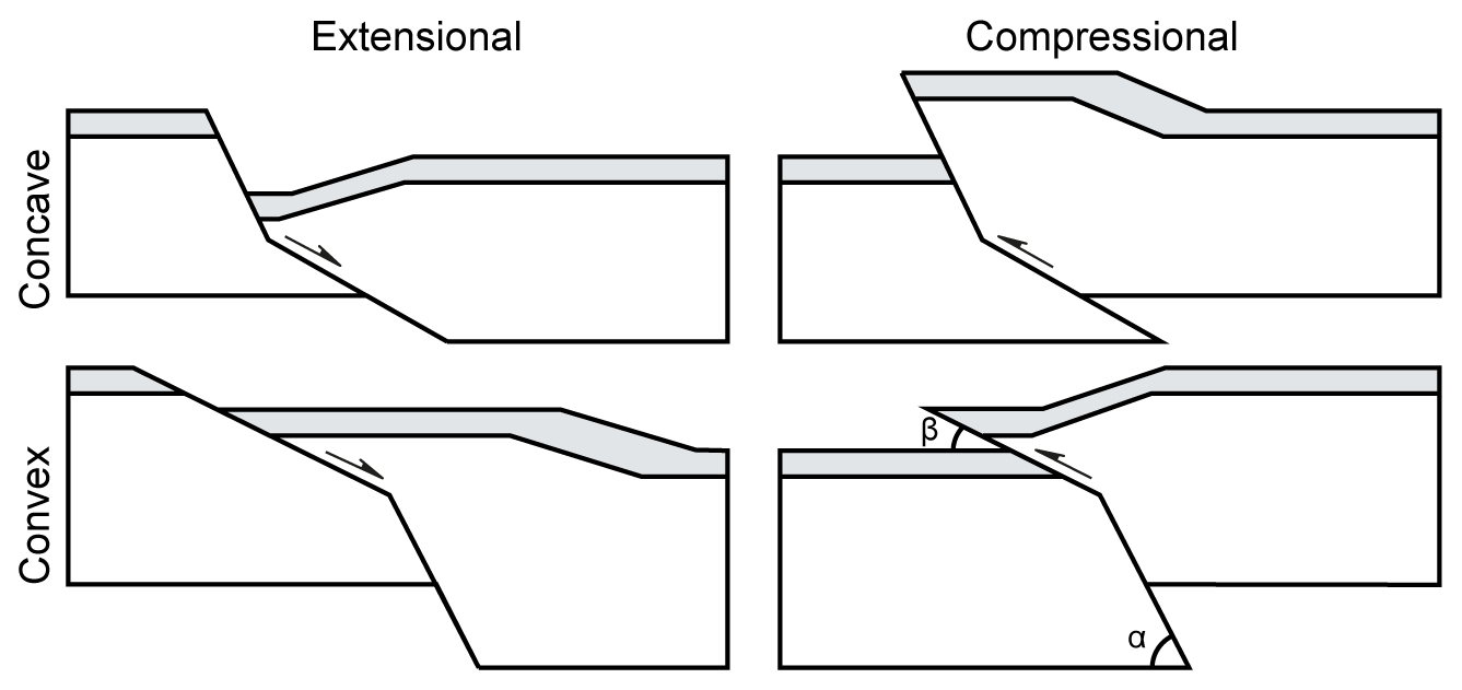
Figure 1Cartoons illustrating concave and convex (to the hangingwall) fault bends and the associated hangingwall deformation in extensional and compressional tectonic settings.
Previous related work in contractional settings has often focused on understanding and modelling the shapes of folds associated with fault bends (e.g. Boyer and Elliott, 1982; Suppe, 1983; Mitra, 1986; Hardy, 1995; Medwedeff and Suppe, 1997; Tavani et al., 2005). This emphasis mainly derives from the importance of fault bends and associated ramp-flat geometries in thrust systems and from circumstances in which fault-bend folding is often easier to define than the fault displacements that are responsible for its development. Displacement distributions along nonplanar thrusts have been examined as an indicator of different fault-bend folding styles (Hughes et al., 2014), but the analysis of displacement variations is much less common than within extensional settings.
Normal fault studies have investigated the geometry of hangingwall rollover in relation to the shape (i.e. bends) of listric normal faults (e.g. Gibbs, 1984; Williams and Vann, 1987; Xioa and Suppe, 1992; Withjack and Schlische, 2006; Xiaoli et al., 2015) in particular, but the recognition that normal faults are often approximately planar in comparison to the ramp-flat geometries in thrust systems has meant that other models are often used to explain the deformation geometries surrounding normal faults, including hangingwall rollover and footwall uplift (e.g. King et al., 1988; Marsden et al., 1990; Roberts and Yielding, 1994; Healy et al., 2004). Structural studies have therefore often concentrated on defining displacement distributions as a means of investigating fault growth (e.g. Walsh and Watterson, 1988; Scholz et al., 1993; Roche et al., 2012; Torabi et al., 2019), with fewer studies examining the geometries of associated fault-bend folds and the nature of strain partitioning along nonplanar normal faults (e.g. Homberg et al., 2017).
In this paper, we present a new quantitative model for the relationship between down-dip fault bend geometry and strain partitioning along normal faults, and we demonstrate its applicability to different geological examples. We highlight how small-scale irregularities (i.e. bends) are responsible for changes in fault throw, the vertical component of displacement and the most widely used measure of displacement in the analysis of normal faults. We suggest that a geometrical origin for changes in fault throw is relatively common, since most, if not all, faults have irregular geometries on a range of scales. Fault surface irregularities can arise from a variety of processes, including refraction and segmentation, that are often linked to the mechanical stratigraphy of the faulted sequence (Wallace, 1861; Peacock and Zhang, 1994; Sibson, 2000; Schöpfer et al., 2007a, b). The local variations in the component of fault throw along fault bends are accommodated by folding (i.e. continuous deformation) and faulting (i.e. discontinuous deformation) and have implications for interpretations of fault growth and for a variety of practical applications, such as (i) across-fault juxtaposition and sealing, (ii) the generation of fault-related traps, both in terms of four-way and three-way dip closures, and (iii) assessments of hazard and earthquake slip.
This study focuses on how strain is locally partitioned at fault bends along normal faults that are approximately planar on large scales. The model assumes that the vertical component of displacement, referred to here as total throw (Tt), is constant and the displacement measured along the fault is also constant (Fig. 2). These circumstances demand that the discontinuous throw (Td) must change around fault irregularities and the difference between the total throw and the discontinuous throw must be accommodated by deformation of the wall rocks. Wall rock deformation can be in the form of folding or of minor faults; here we consider only folding as the means of accommodating the difference between Td and Tt. These simple boundary conditions can give rise to a very wide range of behaviours and patterns of wall rock deformation depending on which other assumptions are applied. For illustrative purposes, we present the potential structures developed at fault bends arising from two additional and relatively conventional assumptions, the implications of which we will discuss later:
-
Strain of the wall rock is accommodated exclusively by deformation of the hangingwall block with the footwall remaining rigid (i.e. undeformed). The notion of a relatively undeformed footwall is commonly used and finds support from studies of planar normal faults that intersect the free surface (e.g. King et al., 1988; Roberts and Yielding, 1994; Healy et al., 2004) and is a configuration that is routinely replicated in analogue models.
-
The hangingwall block is translated parallel to the lower fault segment, with wall-rock deformation accommodating space problems adjacent to the upper fault segment. For example, in the concave extensional case illustrated in Fig. 1 an increase in Td on the upper horizon due to the difference in the angle between the upper and lower fault segments accommodates the space problem caused by the direction of translation of the hangingwall block, while the lower horizon remains flat. The option to consider the hangingwall to be translated parallel to the lower fault segment was chosen because this is again routinely replicated in analogue models, and the resulting geometries are therefore very familiar (i.e. Fig. 1).
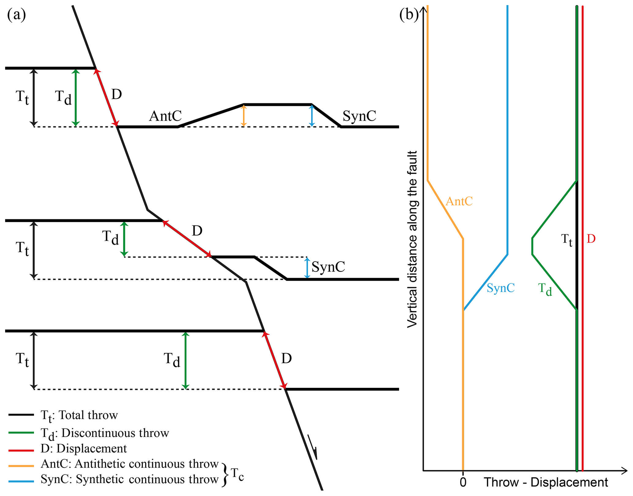
Figure 2(a) Schematic diagram of a fault that comprises three fault segments forming two sharp fault bends, a convex (bottom) and a concave (top). The total throw (Tt) is partitioned into the discontinuous throw (Td) and the continuous throw (Tc); the later comprises the antithetic continuous throw (AntC) and the synthetic continuous throw (SynC). (b) Throw-displacement profiles along the nonplanar fault in (a) showing the complementary variations in the discontinuous and continuous throws given that the total throw and the displacement are constant and unaffected by the fault bends.
Our deformation algorithm applies constant along-fault displacement (D) and total throw (Tt) boundary conditions accommodated by deformation, which is neither constant bed length nor constant volume (e.g. Groshong et al., 2012). The fold geometries are constructed using the method of Groshong (1989), which involves inclined simple shear with axial planes that have a dip equal and opposite to that of the fault surface (Figs. 1, 2, and 4); other methods could have been applied, but the principal conclusions relating to variations in partitioning of discontinuous and continuous throws would have been similar. The basic findings of our modelling are also applicable to faults with gradually changing displacements in line with established displacement-length (D–L) scaling and displacement gradients on faults (e.g. Nicol et al., 2020). Constant along-fault displacement implicitly assumes no propagation-related folding (e.g. Coleman et al., 2019) or associated displacement changes, a reasonable simplifying condition for our study concentrating on fault-bend folding. Figure 2 shows that in these circumstances strain will be accommodated by discontinuous (e.g. fault-related) and continuous (e.g. fold-related) deformation adjacent to fault bends, the nature of which is described below.
Constant fault displacement (D) requires, for example, that the discontinuous throw (Td) decreases above a bend where a fault steepens downwards and is compensated by an increase in continuous throw (Tc; Fig. 2) accommodating deformation of the wall rock in the form of folding. In that sense the development of folding above a fault bend is complementary to the discontinuous throw and contributes to the conservation of a constant total throw across the fault (Tt; Fig. 2). For this case of a fault which steepens downwards and is convex to the hangingwall (i.e. Fig. 1), the continuous component of throw is referred to as synthetic continuous throw (SynC) insofar as it complements and aggregates with the discontinuous throw (Td) to provide the constant total throw (i.e. SynC). By contrast, for a fault bend which shallows downwards and is concave towards the hangingwall (i.e. Fig. 1), the continuous throw is referred to as antithetic continuous throw (AntC) with the total throw equivalent to the difference between the discontinuous and continuous components of throw (i.e. AntC). Synthetic and antithetic continuous throws accommodate down to the hangingwall and footwall bed rotations, respectively, and in that sense are reminiscent of normal and reverse drag bed deformations (Barnett et al. 1987), even if their origin can be very different (see below).
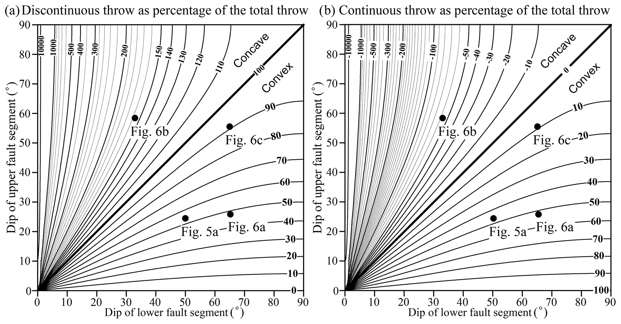
Figure 3Graphs showing the modelled relationship between (a) the discontinuous (Td) and (b) the continuous (Tc) throw, as a proportion of the total throw (Tt), and the dips of the lower and upper fault segments of a sharp fault bend that comprises only two fault segments (i.e. Fig. 1). The geometries of the lower convex bends along the faults at Figs. 5a and 6a, the upper concave bend along the fault at Fig. 6b, and the convex fault bend at Fig. 6c are also plotted.
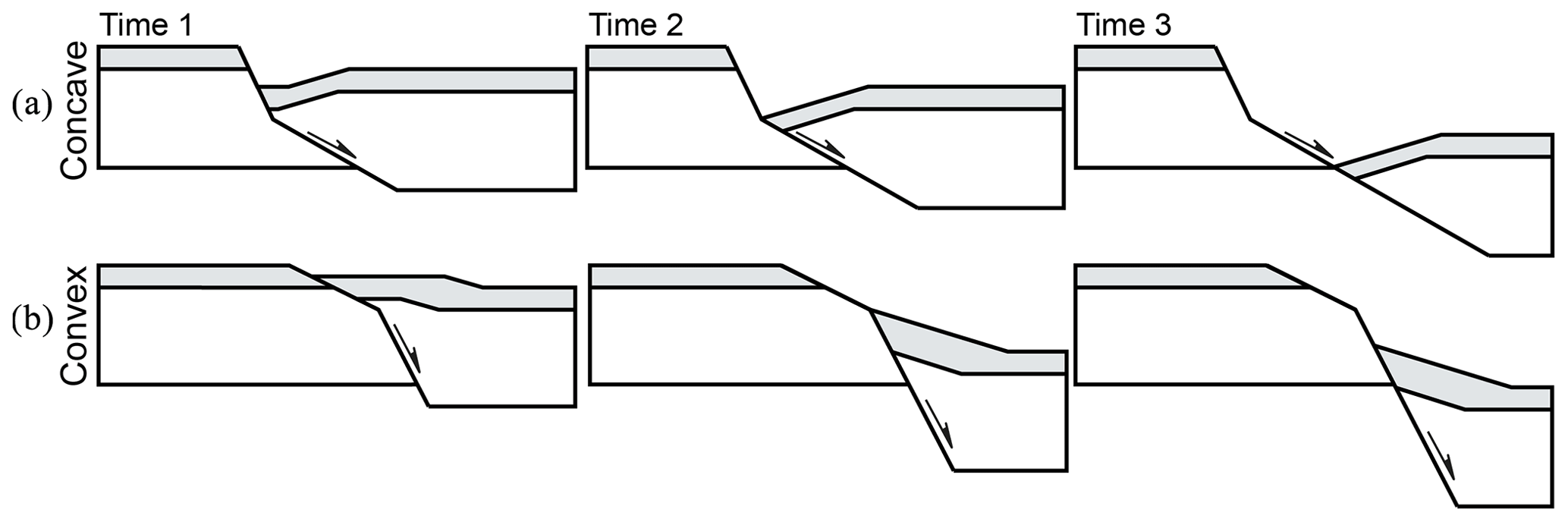
Figure 4Block diagrams illustrating the evolution of the hangingwall deformation associated with (a) concave and (b) convex fault bends with increasing displacement at times 1 to 3. As soon as the hangingwall fault cutoff reaches the bend and begins to move along the lower fault segment (from time 2 to time 3), the absolute amount of continuous deformation does not increase anymore, resulting in a progressive decrease in its proportion to the total throw.
The relative magnitudes of Td and Tt for the simplest case of a sharp fault bend comprising only two fault segments and horizontal pre-faulting bedding (i.e. Fig. 1), is given by
where α and β are the dips of the lower and upper fault segments, respectively (Fig. 1). Figure 3a illustrates the outcome of these calculations (expressed as a percentage) for the whole range of fault dips, while Fig. 3b shows the complementary values for the continuous throw (Tc). In the absence of a bend (i.e. where the lower and upper fault segments have the same dip) the entire total throw is discontinuous. Fault bends which are concave towards the hangingwall show a local increase in discontinuous fault throw on layers with cutoffs straddling the fault bend, whereas fault bends which are convex to the hangingwall show a local decrease in discontinuous throw. The discontinuous throw is therefore less than the total throw for convex fault bends and larger for concave fault bends (Fig. 3). For example, a convex fault bend with a 70∘ dip of the lower fault segment and a 45∘ dip of the upper fault segment will accommodate ca. 75 % of the total throw by discontinuous throw and the remaining ca. 25 % by continuous throw (Fig. 3). The negative values of continuous throw for concave fault bends at Fig. 3b represent the antithetic continuous throw that, as mentioned above, contributes negatively to the total throw.
As the throw on a fault surface increases the significance of the throw partitioning due to a bend will decrease. The plots in Fig. 3 are appropriate to the situation in which the hangingwall cutoff of an offset horizon lies above the bend in the fault (time 1 in Fig. 4). While this condition is maintained, an increase in fault displacement results in a progressive increase in continuous deformation so that its proportion of the total throw remains constant (from time 1 to time 2 in Fig. 4). However, once the hangingwall cutoff reaches the bend and moves along the lower fault segment (from time 2 to time 3 in Fig. 4), the continuous deformation remains constant and becomes a progressively smaller proportion of the total throw.
Faults however often extend beyond a single bend, as illustrated for the fault in Fig. 2a, which comprises three fault segments forming two sharp bends, a lower convex and an upper concave bend. In this case, synthetic continuous deformation is developed along the middle and upper fault segments as a result of the lower convex bend. By contrast, antithetic continuous deformation is developed only along the upper segment as a result of the upper concave bend. The partitioning of displacement across fault bends therefore varies spatially with an individual bed showing multiple deformations depending on how many bends an individual bed is offset across. The main principles of how the strain is partitioned along these fault bends are highlighted by the throw-displacement profiles in Fig. 2b, with complementary variations in the discontinuous and continuous (both, synthetic and antithetic) throws resulting in our prescribed constant total throw (Tt), given that the displacement (D) is also constant.
Whilst our treatment is relatively simple insofar as fault bends in nature are rarely single sharp bends, our comparison with natural examples below shows that the basic conclusions drawn from our analysis can be applied to more continuously curved bends, which are perhaps best considered as continuously curved multiple bend faults (e.g. Withjack et al., 1995; Medwedeff and Suppe, 1997; Shaw et al., 2005). This is because the commonly observed continuously curved fault bends (i.e. Figs. 5 and 6) can be treated as multiple sharp fault bends consisting of many small, planar, fault segments (e.g. Xiao and Suppe, 1992).
A selection of natural faults displaying fault bends and associated folding is presented from seismic (Figs. 5 and 6a) and outcrop (Fig. 6b and c) datasets. These examples highlight the principal features of relatively simple normal faults displaying similar characteristics to those illustrated in Figs. 1, 2, and 4, demonstrating the applicability of the proposed quantitative model of strain partitioning. Some of the fault bend geometries present along the following natural faults are plotted in Fig. 3 to provide an appreciation of which areas in these plots represent realistic fault bend geometries.
3.1 Porcupine Basin, offshore Ireland
A normal fault imaged on depth-converted seismic reflection data from the northwestern Porcupine Basin, offshore western Ireland (Fig. 5; Worthington and Walsh, 2017), has a maximum total throw of ca. 600 m accommodated along a continuously curved fault surface with a sigmoidal shape and comprising both convex and concave bends (Fig. 5a). Accumulation of displacement has resulted in deformation of the hangingwall in the form of anticlinal and monoclinal structures associated with these bends. The throw-displacement profiles along this normal fault indicate that the discontinuous and continuous throws are complementary to each other so that the distribution of their sum (i.e. the total throw) is not affected by the fault bend (Fig. 5b). The magnitude of the displacement is also unaffected by the fault bend, suggesting the validity of the assumptions of the proposed model, with modelled discontinuous and continuous throws showing a good fit to the measured throws (Fig. 5b).
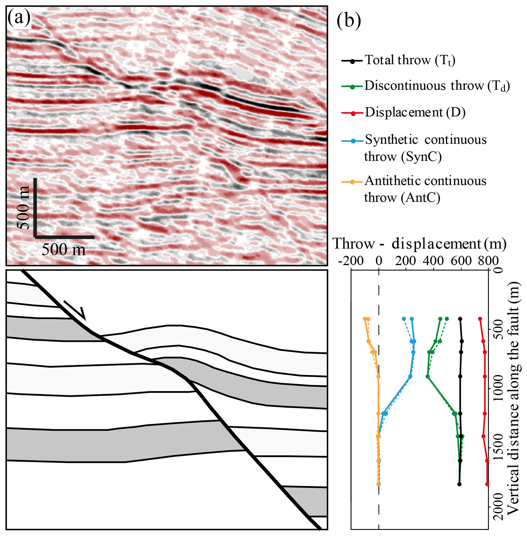
Figure 5(a) Uninterpreted and interpreted seismic profile of a nonplanar fault and associated hangingwall deformation in the northwestern Porcupine Basin, offshore western Ireland. (b) Throw-displacement profiles along the fault in (a) showing the complementary variations in the discontinuous and continuous throws and the distributions of the total throw and the displacement that are unaffected by the fault bends. The modelled discontinuous and continuous throws are also plotted with dashed lines.
An interesting feature of this fault is that the hangingwall rollover geometry associated with the upper part of the fault surface appears to be accommodated by smaller-scale antithetic faults which are close to the limit of seismic resolution. This example illustrates a common feature in which ductile and continuous deformation is accommodated by smaller-scale faulting (i.e. brittle deformation), with, for example, reverse drag and normal drag accommodated by antithetic and synthetic faulting, respectively (Hamblin, 1965; Walsh and Watterson, 1991; Walsh et al., 1996).
3.2 Taranaki Basin, offshore New Zealand
This is a normal fault imaged on high-quality, depth-converted seismic reflection data from the northern Taranaki Basin, offshore western New Zealand (Fig. 6a; Giba et al., 2012). It has a maximum total throw of ca. 900 m, which is again accommodated along a continuously curved fault surface with a sigmoidal shape which comprises both convex and concave bends (Fig. 6a). In this case, fault displacement relative to fault bend geometry generates the full range of folding, with antithetic and synthetic shear associated with shallowing and steepening bends, respectively. Due to the decrease in along-fault discontinuous throw associated with the shallower parts of the fault surface, preservation of the total throw is accommodated by a concomitant increase in synthetic shear as the fault steepens at greater depths (i.e. pink horizon at Fig. 6a). Conversely, due to the upper concave bend, antithetic shear is generated, which is partly accommodated by minor antithetic faults and which, in combination with the synthetic shear, result in the formation of an anticlinal rollover structure. These deformations indicate that the discontinuous throws along a fault surface do not account for the total throw, which should, instead, take account of the fault-related folding with, for example, the aggregation of discontinuous fault throw and synthetic/antithetic shears.
The origin of fault bending for this example illustrates that fault bends need not be simple cylindrical subhorizontal bends arising from fault refraction through different mechanical layers. The observed fault bend arises from twisting and segmentation of an upward propagating fault, circumstances that have generated a left-hand bend arising from left stepping in map view into the plane of observation (see Giba et al., 2012, for further details). This configuration generates both lateral and vertical changes in the discontinuous throw, which are not representative of the throw across the fault unless account is taken of the associated fault-bend folding.
3.3 Wadi Matulla, Sinai, Egypt
This is a normal fault within the Coniacian–Santonian Matulla Formation which contains mixed siliciclastic and carbonate sediments (Fig. 6b; Fossen, 2016; Sharib et al., 2019). The fault with an estimated throw of ca. 3 m shows a rollover anticline associated with a fault surface which has a sigmoidal shape comprising both convex and concave bends (Fig. 6b). This outcrop example clearly illustrates that a significant proportion of the deformation associated with fault-bend folding (i.e. anticline) can be accommodated by minor antithetic and/or synthetic faulting.
3.4 Kilve, Somerset, UK
Upper Jurassic normal faults within the Liassic limestone-shale sequences of Kilve often show near-fault deformations associated with fault surface irregularities arising from fault refraction (Peacock and Zhang, 1994; Schöpfer et al., 2007a, b), in which faults are steeper within limestones and shallower within shales. The significance of associated fault-bend folds varies with the nature of the host-rock stratigraphy and with fault displacement, with smaller folds transected by more through-going fault surfaces at higher displacements (Schöpfer et al., 2007a, b). Fig. 6c shows a fault with hangingwall normal drag associated with a downward steepening fault generated by a triplet of limestone beds bounded by overlying and underlying shales. Displacement is on the same scale as the triplet of layers, and fault-related folding is already bounded and/or bypassed by what are interpreted to be newly developed slip surfaces.
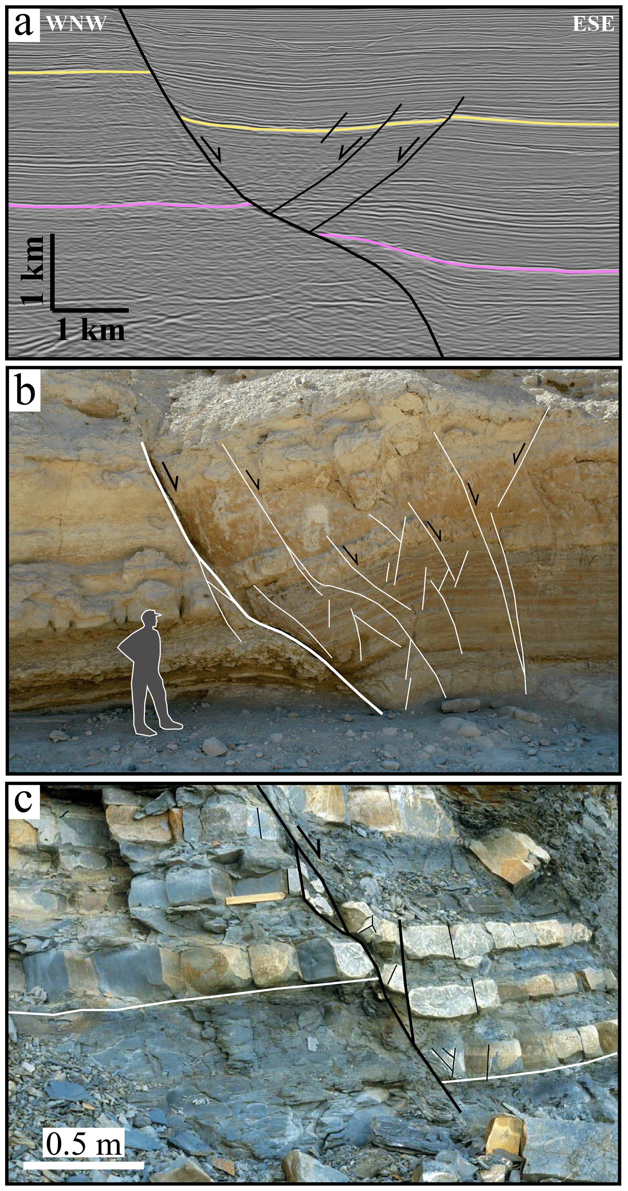
Figure 6(a) Interpreted seismic section of a nonplanar fault and associated hangingwall deformation in the Taranaki Basin, offshore west of North Island/Te Ika-a-Māui, New Zealand. Deformation arises from movement on a fault bend produced by twisting and segmentation of an upward propagating fault (modified after Giba et al., 2012). (b) Outcrop example of a rollover anticline associated with a fault surface which has a sigmoidal shape from Wadi Matulla, Sinai, Egypt (modified from Fossen, 2016). (c) Outcrop example of a fault with 0.5 m throw contained within the Liassic limestone–shale sequence of Kilve, Somerset, UK, showing normal drag arising from a convex upward bend (and fault steepening). See text for more details.
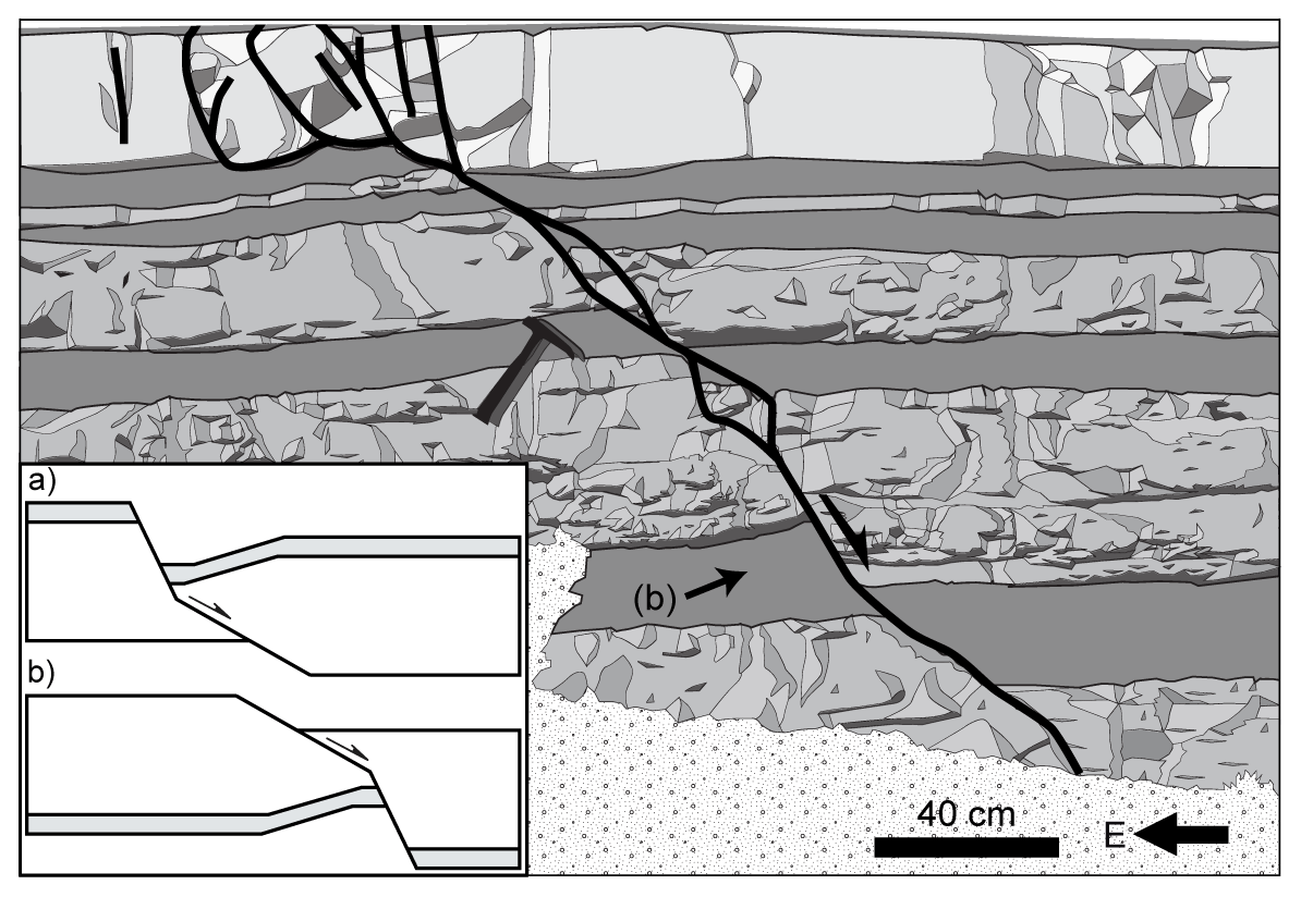
Figure 7Outcrop sketch of a small normal fault from the Mesozoic Southeastern Basin of France (after Roche et al., 2012). Pronounced reverse drag in the footwall of the fault occurs below the upward shallowing of the fault surface to display the geometry illustrated in the inset (b). Inset (a) is copied from Fig. 1, and (b) is (a) rotated through 180∘.
4.1 Model assumptions
The proposed quantitative model of strain partitioning along nonplanar faults assumes that the displacement and the total throw are constant, as illustrated in Fig. 2, or vary systematically in line with the D–L scaling and the displacement gradients observed on faults (e.g. Nicol et al., 2020). A consequence of this assumption is that the bed length and/or thickness may not remain constant during deformation. This is in contrast with the fault-bend folding theory proposed by Suppe (1983) that assumes conservation of area and constant layer thickness implying conservation of bed length and abrupt changes in the displacement at fault bends. While this theory has been extensively applied to compressional settings, it may not be valid for extensional settings given that it is geometrically impossible to preserve the layer thickness along nonplanar faults that have steep fault dips relative to bedding (Suppe, 1983). This is consistent with other studies suggesting that bed length and/or thickness does not remain constant during: (i) displacement accumulation along fault bends in both, compressional (e.g. Groshong et al., 2012) and extensional (Xiao and Suppe, 1992; Poblet and Bulnes, 2005) settings, (ii) the accommodation of displacement gradients along planar faults (e.g. Barnett et al., 1987), and (iii) the strains associated with vertically segmented faults (e.g. Childs et al., 1996). Taken together the available evidence supports the notion that bed length and/or thickness changes can accommodate the strains and folding associated with either constant or slowly changing displacement and total throw along nonplanar faults. Typical deformations adjacent to normal faults include normal drag or reverse drag folding, sometimes accommodated by minor faults.
The hangingwall deformation associated with fault bends is generally considered to be accommodated only by continuous deformation, i.e. folding and ductile strain. However, examples of fault bends in outcrops (e.g. Fig. 6b), experimental models (e.g. Withjack and Schlische, 2006), and high-resolution seismic reflection data (e.g. Fig. 6a) indicate that a proportion of the hangingwall deformation can be accommodated by secondary faulting that is synthetic and/or antithetic to the main fault (e.g. Fig. 6). Whether hangingwall deformation is accommodated by folding and/or secondary faulting will depend on the mechanical properties of the faulted sequence and the strain rate. Differentiation between these two deformation components will largely depend on the quality and resolution of the available data; for example, seismic datasets will image hangingwall deformation as a ductile strain when it is accommodated by faults with displacements below seismic resolution (up to 20 m throw for good quality seismic data; Walsh et al., 1996).
The basic assumption of the model, that displacement and total throw are constant or vary in a regular manner down a fault trace, provides a basis for evaluating the partitioning of the total throw into discontinuous throw at the fault surface and continuous throw accommodated by wall rock deformation. These conditions can be fulfilled in many ways and by a range of different deformation geometries. This paper considers a small subset of these geometries as it is restricted to the case where only the hangingwall is deformed and translation of the hangingwall is parallel to the fault trace below the fault bend (i.e. Fig. 1). These restrictions allow for calculation of unique values for throw partitioning for any combination of fault dips above and below a bend (Fig. 3). This restricted case was addressed because it generates geometries that are familiar from seismic mapping and from analogue models of deformation of a cover sequence above a rigid basement. However, for bends on blind faults or parts of faults that are distant from the free surface, there is no reason to expect that either of these restrictions applies, and it is possible that fault bends will impact equally on the footwall and hangingwall and on horizons above and below a bend. The range of wall rock geometries that could be predicted from this model is therefore much broader than using our more restricted case; this broader range could even provide end-member geometries at bends on blind faults that, for example, are the equivalent of viewing Fig. 1 upside down. Many of these and other geometries that can be considered appear unlikely and may not occur in nature, but many do. For example, Fig. 7 shows a field sketch in which local reverse drag in the footwall of a fault with a maximum throw of ca. 20 cm appears to occur in response to an upward shallowing of the fault in a geometry that is the upside down equivalent of a hangingwall rollover (inset Fig. 7). Whilst these considerations suggest that there may be a range of near-fault horizon geometries due to fault surface irregularities, our approach allows us to investigate the variations in throw and strain partitioning along faults with bends, rather than to define the precise nature of the deformation along a particular fault.
4.2 Evolution of fault zones
Any fault characterized by fault bends will show associated folding and/or bed rotations of the host rock. These deformations will be reminiscent of both normal and reverse drag folding, which are, respectively, in sympathy with or in opposition to the sense of shear accommodated by the fault. Normal drag is often considered to be precursory (i.e. fault-propagation fold; Fig. 1 in Coleman et al., 2019), forming as monoclines between different stratigraphic sequences (i.e. Ferrill et al., 2017) or between different fault segments (i.e. Childs et al., 2017). Normal fault surfaces which are convex towards the hangingwall and downward steepening will however generate hangingwall normal drag (e.g. convex fault bend in Fig. 4b), a phenomenon which accompanies fault movement and is geometrically and mechanically equivalent to so-called frictional drag (i.e. Davis et al., 2011; Fig. 1 in Coleman et al., 2019) but on a macroscopic rather than microscopic scale. Reverse drag is generally attributed to large-scale bed rotations that are in opposition to the fault-parallel shear, giving rise to hangingwall rollover and footwall uplift associated with normal faults, whether they have listric or planar geometries (Barnett et al., 1987). Since conventional reverse drag occurs on much greater length scales than those considered here (i.e. approaching the length of a fault rather than that of a fault bend), any geometrical similarity and localized steepening of bed dips in opposition to fault dip (e.g. concave fault bend in Fig. 4a) is linked to fault bend geometry (and downward shallowing) rather than conventional reverse drag. Whatever the nature of drag, with subsequent growth these deformed host rocks will often be bypassed by through-going slip surfaces, to provide a fault zone with rotated packages of host rock bounded by slip surfaces. For displacements which are larger than the scale of fault bends, host rock deformation will be cumulative, and whilst it is, in principle, possible that beds could become more folded, increased fault displacement is more likely to provide increasing cumulative deformation leading to progressive fault rock generation. In that sense, the presence of fault bends will provide the locus of fault rock generation as displacements accumulate with fault growth, a model that is aligned with the geometric model for fault zone growth outlined by Childs et al. (2009).
4.3 Implications
Since fault throw is the most commonly used measure of fault offset in extensional fault systems, an important implication of the proposed model is that the throw measured at normal fault surfaces varies with fault bends and irregularities. On an approximately planar fault surface with constant total throw, relatively smaller-scale bends can lead to local discontinuous fault throws which are greater or less than the total throw. Previous work shows that while fault throws vary systematically along the length of individual faults, smaller-scale variations can occur (e.g. Walsh and Watterson, 1987; Cartwright and Mansfield, 1998; Manighetti et al., 2001; Nixon et al., 2014; Childs et al., 2017). Our quantitative model suggests that some of those variations arise from local changes in fault geometry such as those accompanying the generation of fault segments and fault refraction processes that can occur on a range of scales even on the same fault. These local effects are best accounted for by either including near-field bed rotations or measuring fault throws from hangingwall and footwall bed elevations beyond the near-field, bend-related deformations adjacent to fault surfaces. Accounting for this partitioning of throw will lead to along-fault throw variations which are more systematic than local throw values, reflecting the coherence of throw variations on faults arising from propagation-related complexities, such as refraction and segmentation. Whatever the nature and origin of fault bends, our quantitative model suggests that throw measurements that do not incorporate bend-related deformations may be subject to throw errors of up to ca. 50 % for realistic fault bend geometries, which are nevertheless towards the upper end of what is likely in nature (up to ca. 40∘; Figs. 3, 5 and 6). However, even for modest fault bends of up to 10∘, on faults with characteristic normal fault dips larger than ca. 50∘, apparent throw variations of ca. 10 % are predicted.
The presence of fault bends and associated deformation can also have implications for a variety of practical purposes. The partitioning of fault displacement into continuous rather than discontinuous deformation will affect across-fault juxtapositions and if developed at sub-seismic scales can have a profound impact on fault seal assessments. The development of associated folding can also generate potential fault-bend-related hangingwall traps, both in terms of three- and four-way dip closures, to either hydrocarbons or mineral systems. Furthermore, the deformation of the host rock sequence due to down-dip fault surface irregularities should be considered when assessing hazards and earthquake slips because fault scarp dips can be ill-defined, with easily measured discontinuous throw varying with fault bend geometries. Previous studies on coseismic throw variations along surface ruptures (e.g. Walker at al., 2009; Iezzi et al., 2018) have also identified strain partitioning associated with fault dip changes in along-strike bends that were attributed to both lateral and up-dip propagation of two faults that are non-collinear. Our model is consistent with those observations and can also be reconciled with other kinematic interpretations, such as the exclusively up-dip propagation, bifurcation, and twisting of a single fault. Whatever their precise kinematic origin, these fault throw variations, as Iezzi et al. (2018) demonstrated, can also explain the scatter in maximum offset versus surface rupture length scaling relationships (e.g. Wells and Coppersmith, 1994).
- i.
A quantitative model has been presented for the throw variations and strain partitioning associated with fault-bend folding along normal faults with fault surface irregularities arising from propagation-related phenomenon (e.g. refraction or segmentation).
- ii.
The main feature of this model is that the variations in discontinuous and continuous throws along nonplanar normal faults are complementary given that the displacement and total throw are constant and not affected by the fault bends.
- iii.
This model shows that small-scale normal and reverse drag arise from fault bends that steepen or shallow downwards, respectively. Normal drag in this case arises from deformation, which is equivalent to macroscopic-scale frictional drag rather than a precursory phenomenon.
- iv.
Whatever the nature of fault-bend folding, it can have a significant effect on the measured across-fault throw, the main measure used for quantifying offset across normal faults.
- v.
The fault throw can be subject to errors of up to ca. 10 % and ca. 50 % for fault bend geometries of between ca. 10 and 40∘, respectively, even on otherwise sub-planar faults with constant displacement.
- vi.
Fault-bend folding will be developed in mechanically anisotropic host rock sequences where processes such as refraction and segmentation are promoted, and failure to identify their significance will lead to erroneous kinematic interpretations.
- vii.
Fault-bend folding is expected to occur on a range of scales that are related to the mechanical stratigraphy.
Seismic and well data for Porcupine Basin, offshore western Ireland, were provided by the Petroleum Affairs Division of the Department of Communications, Climate Action and Environment, Ireland (http://www.pad.gov.ie, Petroleum Affairs Division, 2020).
ED was responsible for conceptualization, data curation, methodology, visualization, and primary writing of the paper. MMS contributed to data curation and interpretation, validation, and article editing. JJW performed investigation, data curation and interpretation, and primary writing of the paper. VR contributed to data curation and interpretation and article editing. CC performed investigation, data interpretation, and article editing.
The authors declare that they have no conflict of interest.
We gratefully acknowledge the Petroleum Affairs Division (PAD) of the Department of Communications, Climate Action and Environment (DCCAE), Ireland, for providing the seismic and well data. The authors would like to thank Schlumberger for providing access to Petrel software. Thanks also to other members of the Fault Analysis Group for useful technical discussions. We also thank Oliver B. Duffy and Zoe Mildon for their helpful reviews and Mark Allen for editorial handling.
This research has been supported in part by a research grant from Science Foundation Ireland (SFI) and cofunded under the European Regional Development Fund and by PIPCO RSG and its member companies (grant no. 13/RC/2092).
This paper was edited by Mark Allen and reviewed by Oliver B. Duffy and Zoe Mildon.
Barnett, J. A., Mortimer, J., Rippon, J. H., Walsh, J. J., and Watterson, J.: Displacement geometry in the volume containing a single normal fault, AAPG Bull., 71, 925–937, 1987.
Boyer, S. E. and Elliott, D.: Thrust systems, AAPG Bull., 66, 1196–1230, 1982.
Cartwright, J. A. and Mansfield, C. S.: Lateral displacement variation and lateral tip geometry of normal faults in the Canyonlands National Park, Utah, J. Struct. Geol., 20, 3–19, 1998.
Chen, Y. G., Lai, K. Y., Lee, Y. H., Suppe, J., Chen, W. S., Lin, Y. N. N., Wang, Y., Hung, J. H., and Kuo, Y. T.: Coseismic fold scarps and their kinematic behavior in the 1999 Chi-Chi earthquake Taiwan, J. Geophys. Res.-Sol. Ea., 112, B03S02, https://doi.org/10.1029/2006JB004388, 2007.
Childs, C., Nicol, A., Walsh, J. J., and Watterson, J.: Growth of vertically segmented normal faults, J. Struct. Geol., 18, 1389–1397, 1996.
Childs, C., Manzocchi, T., Walsh, J. J., Bonson, C. G., Nicol, A., and Schöpfer, M. P. J.: A geometric model of fault zone and fault rock thickness variations, J. Struct. Geol., 31, 117–127, 2009.
Childs, C., Manzocchi, T., Nicol, A., Walsh, J. J., Soden, A. M., Conneally, J. C., and Delogkos, E.: The relationship between normal drag, relay ramp aspect ratio and fault zone structure, Geol. Soc. Lond. Spec. Publ., 439, 355–372, 2017.
Coleman, J. A., Duffy, B. O., Jackson, A.-L. C.: Growth folds above propagating normal faults, Earth-Sci. Rev., 126, 102885, https://doi.org/10.1016/j.earscirev.2019.102885, 2019.
Davis, G. H., Reynolds, S. J., and Kluth, C. F.: Structural geology of rocks and regions, John Wiley & Sons, Hoboken, New Jersey, USA, 2011.
Deng, H. and McClay, K.: Development of extensional fault and fold system: Insights from 3D seismic interpretation of the Enderby Terrace, NW Shelf of Australia, Mar. Petrol. Geol., 104, 11–28, 2019.
Ferrill, D. A., Morris, A. P., McGinnis, R. N., and Smart, K. J.: Myths about normal faulting, Geol. Soc. Lond. Spec. Publ., 439, 41–56, 2017.
Fossen, H.: Structural geology, Cambridge University Press, Cambridge, UK, 2016.
Giba, M., Walsh, J. J., and Nicol, A.: Segmentation and growth of an obliquely reactivated normal fault, J. Struct. Geol., 39, 253–267, 2012.
Gibbs, A. D.: Structural evolution of extensional basin margins, J. Geol. Soc., 141, 609–620, 1984.
Groshong Jr., R. H.: Half-graben structures: Balanced models of extensional fault-bend folds, Geol. Soc. Am. Bull., 101, 96–105, 1989.
Groshong Jr., R. H., Withjack, M. O., Schlische, R. W., and Hidayah, T. N.: Bed length does not remain constant during deformation: Recognition and why it matters, J. Struct. Geol., 41, 86–97, 2012.
Hamblin, W. K.: Origin of “Revere drag” on the downthrown side of normal faults, GSA Bull., 76, 1145–1164, 1965.
Hardy, S.: A method for quantifying the kinematics of fault-bend folding, J. Struct. Geol., 17, 1785–1788, 1995.
Healy, D., Yielding, G., and Kusznir, N.: Fracture prediction for the 1980 El Asnam, Algeria earthquake via elastic dislocation modeling, Tectonics, 23, TC6005, https://doi.org/10.1029/2003TC001575, 2004.
Homberg, C., Schnyder, J., Roche, V., Leonardi, V., and Benzaggagh, M.: The brittle and ductile components of displacement along fault zones, Geol. Soc. Lond. Spec. Publ., 439, 395–412, 2017.
Hughes, A. N. and Shaw, J. H.: Fault displacement-distance relationships as indicators of contractional fault-related folding style, AAPG Bull., 98, 227–251, 2014.
Iezzi, F., Mildon, Z., Walker, J. F., Roberts, G., Goodall, H., Wilkinson, M., and Robertson, J.: Coseismic throw variation across along-strike bends on active normal faults: Implications for displacement versus length scaling of earthquake ruptures, J. Geophys. Res.-Sol. Ea., 123, 9817–9841, 2018.
King, G. C. P., Stein, R. S., and Rundle, J. B.: The growth of geological structures by repeated earthquakes, 1. Conceptual framework, J. Geophys. Res.-Sol. Ea., 93, 13307–13318, 1988.
Manighetti, I., King, G. C. P., Gaudemer, Y., Scholz, C. H., and Doubre, C.: Slip accumulation and lateral propagation of active normal faults in Afar, J. Geophys. Res.-Sol. Ea., 106, 13667–13696, 2001.
Marsden, G., Yielding, G., Roberts, A. M., and Kusznir, N. J.: Application of a flexural cantilever simple-shear/pure shear model of continental lithosphere extension to the formation of the northern North Sea basin, in: Tectonic evolution of the North Sea rifts, edited by: Oxfor McClay, K. R., Extensional fault systems in sedimentary basins: a review of analogue model studies, Mar. Petrol. Geol., 7, University Press Oxford, 240–261, 1990.
Medwedeff, D. A. and Suppe, J.: Multibend fault-bend folding, J. Struct. Geol., 19, 279–292, 1997.
Mitra, S.: Duplex structures and imbricate thrust systems: Geometry, structural position, and hydrocarbon potential, AAPG Bull., 70, 1087–1112, 1986.
Nicol, A., Walsh, J. J., Childs, C., and Manzocchi, T.: The growth of faults, in: Understanding Faults: Detecting, Dating, and Modeling, edited by: Tanner, D. and Brandes, C., Elsevier, ISBN: 9780128159859, 221–255, 2020.
Nixon, C. W., Sanderson, D. J., Dee, S. J., Bull, J. M., Humphreys, R. J., and Swanson, M. H.: Fault interactions and reactivation within a normal-fault network at Milne Point, Alaska, AAPG Bull., 98, 2081–2107, 2014.
Peacock, D. C. P. and Zhang, X.: Field examples and numerical modelling of oversteps and bends along normal faults in cross-section, Tectonophysics, 234, 147–167, 1994.
Petroleum Affairs Division: Oil and Gas (Exploration & Production), Department of Communications, Climate Action and Environment, Ireland, available at: http://www.pad.gov.ie, last access: 20 May 2020.
Poblet, J. and Bulnes, M.: Fault-slip, bed-length and area variations in experimental rollover anticlines over listric normal faults: influence in extension and depth to detachment estimations, Tectonophysics, 396, 97–117, 2005.
Roberts, A. and Yielding, G.: Continental extensional tectonics, in: Continental Deformation, Pergamon Press, Oxford, 223–250, 1994.
Roche, V., Homberg, C., and Rocher, M.: Fault displacement profiles in multilayer systems: from fault restriction to fault propagation, Terra Nova, 24, 499–504, 2012.
Scholz, C. H., Dawers, N. H., Yu, J. Z., Anders, M. H., and Cowie, P. A.: Fault growth and fault scaling laws: preliminary results, J. Geophys. Res.-Sol. Ea., 98, 21951–21961, 1993.
Schöpfer, M. P. J., Childs, C., and Walsh, J. J.: 2D Distinct Element modeling of the structure and growth of normal faults in multilayer sequences, Part 1: Model calibration, boundary conditions and selected results, J. Geophys. Res., 112, B10401, https://doi.org/10.1029/2006JB004902, 2007a.
Schöpfer, M. P. J., Childs, C., Walsh, J. J., Manzocchi, T., and Koyi, H. A.: Geometrical analysis of the refraction and segmentation of normal faults in periodically layered sequences, J. Struct. Geol., 29, 318–335, 2007b.
Serck, S. C. and Braathen A.: Extensional fault and fold growth: impact on accommodation evolution and sedimentary infill, Basin Res., 31, 967–990, 2019.
Sharib, A., Ahmed, S. A. A., Selim, A. Q., Abdel Fattah, M. M., Hassan, S. M., and Sanislav, I. V.: Thermal Alteration of Organic Matter in the Contact of a Rift-Related Basaltic Dyke: An Example from the Black Limestone, Wadi Matulla, West Central Sinai, Egypt, Minerals, 9, 279–305, 2019.
Shaw, J. H. and Suppe, J.: Earthquake hazards of active blind-thrust faults under the central Los Angeles basin, California, J. Geophys. Res.-Sol. Ea., 101, 8623–8642, 1996.
Shaw, J. H., Connors, C. D., and Suppe, J. (Eds.): Seismic interpretation of contractional fault-related folds: An AAPG seismic atlas, Vol. 53, AAPG, 1–157, 2005.
Sibson, R. H.: Fluid involvement in normal faulting, J. Geodynam., 29, 469–499, 2000.
Suppe, J.: Geometry and kinematics of fault-bend folding, Am. J. Sci., 283, 684–721, 1983.
Tavani, S., Storti, F., and Salvini, F.: Rounding hinges to fault-bend folding: geometric and kinematic implications, J. Struct. Geol., 27, 3–22, 2005.
Torabi, A., Alaei, B., and Libak, A.: Normal fault 3D geometry and displacement revisited: Insights from faults in the Norwegian Barents Sea, Mar. Petrol. Geol., 99, 135–155, 2019.
Walker, J. F., Roberts, G. P., Cowie, P. A., Papanikolaou, I. D., Sammonds, P. R., Michetti, A. M., and Phillips, R. J.: Horizontal strain-rates and throw-rates across breached relay zones, central Italy: Implications for the preservation of throw deficits at points of normal fault linkage, J. Struct. Geol., 31, 1145–1160, 2009.
Wallace, W.: The laws which regulate the deposition of lead ores in veins: illustrated by an examination of the geological structure of the mining districts of Alston Moor, Edw. Stanford, London, 354–357, 1861.
Walsh, J. J. and Watterson, J.: Distributions of cumulative displacement and seismic slip on a single normal fault surface, J. Struct. Geol., 9, 1039–1046, 1987.
Walsh, J. J. and Watterson, J.: Analysis of the relationship between displacements and dimensions of faults, J. Struct. Geol., 10, 239–247, 1988.
Walsh, J. J. and Watterson, J.: Geometric and kinematic coherence and scale effects in normal fault systems, Geol. Soc. Lond. Spec. Publ., 56, 193–203, 1991.
Walsh, J. J., Watterson, J., Childs, C., and Nicol, A.: Ductile strain effects in the analysis of seismic interpretations of normal fault systems, Geol. Soc. Lond. Spec. Publ., 99, 27–40, 1996.
Wells, D. L. and Coppersmith, K. J.: New empirical relationships among magnitude, rupture length, rupture width, rupture area, and surface displacement, Bull. Seismol. Soc. Am., 84, 974–1002, 1994.
Williams, G. and Vann, I.: The geometry of listric normal faults and deformation in their hangingwalls, J. Struct. Geol., 9, 789–795, 1987.
Withjack, M. O. and Schlische, R. W.: Geometric and experimental models of extensional fault-bend folds, Geol. Soc. Lond. Spec. Publ., 253, 285–305, 2006.
Withjack, M. O., Islam, Q. T., and La Pointe, P. R.: Normal faults and their hanging-wall deformation: an experimental study, AAPG Bull., 79, 1–17, 1995.
Worthington, R. P. and Walsh, J. J.: Timing, growth and structure of a reactivated basin-bounding fault, Geol. Soc. Lond. Spec. Publ., 439, 511–531, 2017.
Xiao, H. and Suppe, J.: Origin of Rollover, AAPG Bull., 76, 509–529, 1992.
Xiao, H. B. and Suppe, J.: Role of compaction in listric shape of growth normal faults, AAPG Bull., 73, 777–786, 1989.
Xiaoli, Z., Guangyu, H., Senqing, H., Zewei, Y., Hui, W., and Lu, L.: Improved Geometric Model of Extensional Fault-bend Folding, Acta Geol. Sin.-Engl. Edn., 89, 1847–1857, 2015.