the Creative Commons Attribution 4.0 License.
the Creative Commons Attribution 4.0 License.
 | 20 Jan 2021
Analysis of deformation bands associated with the Trachyte Mesa intrusion, Henry Mountains, Utah: implications for reservoir connectivity and fluid flow around sill intrusions
Penelope I. R. Wilson
Robert W. Wilson
David J. Sanderson
Ian Jarvis
Kenneth J. W. McCaffrey
Shallow-level igneous intrusions are a common feature of many sedimentary basins, and there is increased recognition of the syn-emplacement deformation structures in the host rock that help to accommodate this magma addition. However, the sub-seismic structure and reservoir-scale implications of igneous intrusions remain poorly understood. The Trachyte Mesa intrusion is a small (∼1.5 km2), NE–SW trending satellite intrusion to the Oligocene-age Mount Hillers intrusive complex in the Henry Mountains, Utah. It is emplaced within the highly porous, aeolian Entrada Sandstone Formation (Jurassic), producing a network of conjugate sets of NE–SW striking deformation bands trending parallel to the intrusion margins. The network was characterized by defining a series of nodes and branches, from which the topology, frequency, intensity, spacing, characteristic length, and dimensionless intensity of the deformation band traces and branches were determined. These quantitative geometric and topological measures were supplemented by petrological, porosity and microstructural analyses. Results show a marked increase in deformation band intensity and significant porosity reduction with increasing proximity to the intrusion. The deformation bands are likely to impede fluid flow, forming barriers and baffles within the Entrada reservoir unit. A corresponding increase in Y- and X-nodes highlights the significant increase in deformation band connectivity, which in turn will significantly reduce the permeability of the sandstone. This study indicates that fluid flow in deformed host rocks around igneous bodies may vary significantly from that in the undeformed host rock. A better understanding of the variability of deformation structures, and their association with intrusion geometry, will have important implications for industries where fluid flow within naturally fractured reservoirs adds value (e.g. hydrocarbon reservoir deliverability, hydrology, geothermal energy and carbon sequestration).
- Article
(63693 KB) - Full-text XML
-
Supplement
(30900 KB) - BibTeX
- EndNote


Syn-emplacement deformation structures (faults, fractures and forced folds) provide the principal mechanism for the accommodation of magma at shallow crustal levels (e.g. Pollard and Johnson, 1973; Hansen and Cartwright, 2006; Senger et al., 2015; Wilson et al., 2016). The thermal effects of intrusions on host rocks have been well studied (e.g. Jaeger, 1964; Irvine, 1970; Brooks Hanson, 1995; Rodriguez-Monreal et al., 2009; Senger et al., 2014; Aarnes et al., 2015; Gardiner et al., 2019), as too has been the hydrothermal fluid flow associated with their emplacement (e.g. Rossetti et al., 2007; Scott et al., 2015). However, the impact of these syn-emplacement deformation structures on post-emplacement fluid flow around intrusions is less well understood (Montanari et al., 2017). Our study is based on detailed kinematic, geometric and spatial analyses of networks of deformation bands in a host-rock sandstone associated with emplacement of the Trachyte Mesa igneous intrusion, Henry Mountains, Utah (Fig. 1). The aims are to: (1) characterize deformation structures developed in the Entrada Sandstone around the intrusion; (2) track geometrical and topological changes towards the intrusion; and (3) discuss the implications of these changes for fluid flow in the host-rock sandstone.
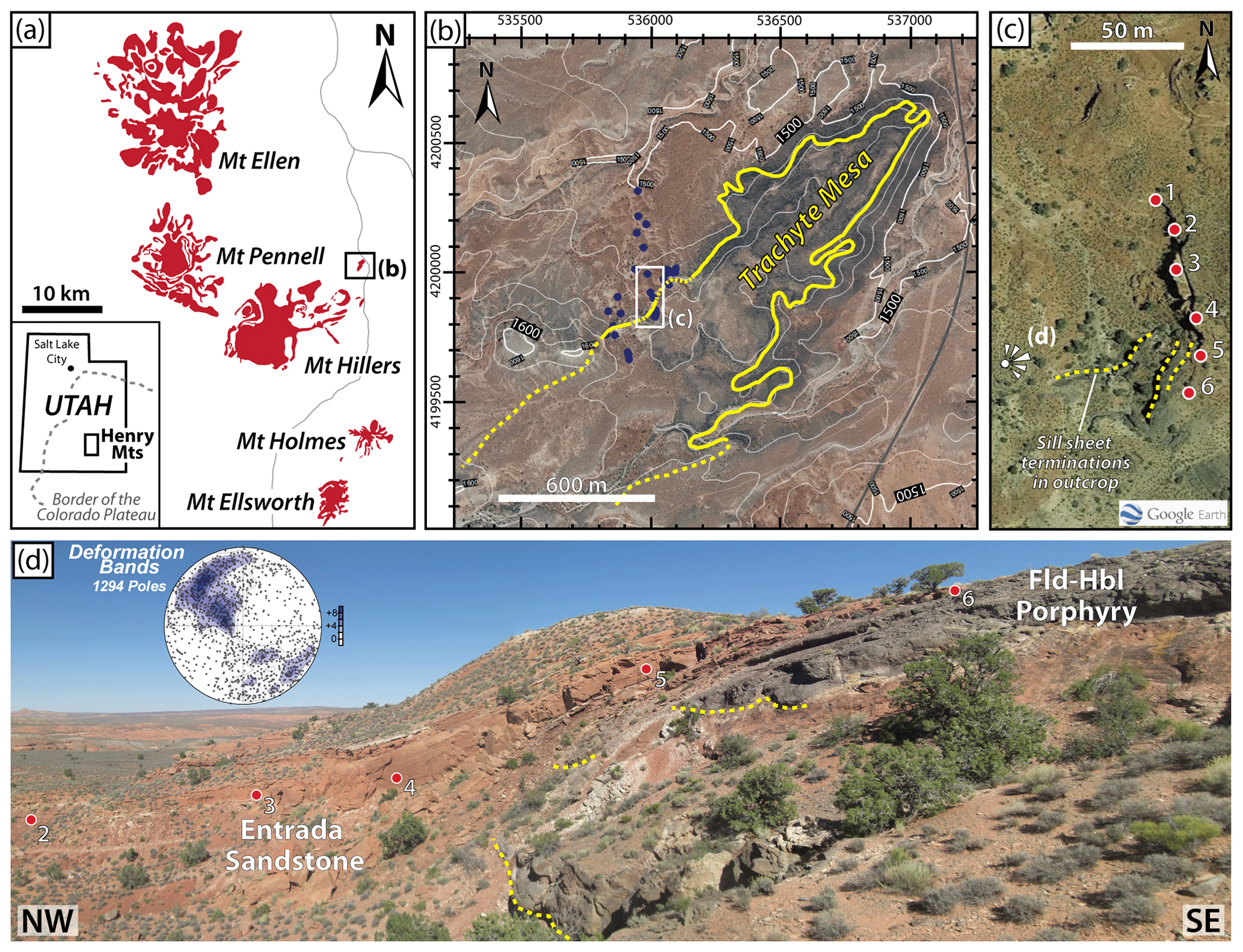
Figure 1Geological setting and study area. (a) Simplified maps showing location of the Henry Mountains intrusive complex and the Trachyte Mesa intrusion. Intrusion areas adapted from Morgan et al. (2008). (b) Contoured (20 m intervals) aerial image (Source data: National Agricultural Imagery Program, https://gis.utah.gov/data/aerial-photography/, last access: 28 December 2020) of the Trachyte Mesa area showing the intrusion outline (yellow) and study area. Dashed lines in the SW depict the sub-surface extent of the intrusion, as defined by Wetmore et al. (2009) from magnetic resistivity data. Blue dots show field localities visited as part of wider reconnaissance studies (Wilson et al., 2016). (c) Satellite photograph (© Google Earth) of the study area (NW margin of the Trachyte Mesa intrusion). Structural stations for fracture studies indicated by numbered red dots. Yellow dashed lines show outcrop exposure of sill sheet terminations. (d) Field photograph showing monoclinal geometry of the NW intrusion margin. Note blocky, red Entrada Sandstone units concordant with the underlying intrusion top surface, and stacked intrusive sheets below (sheet terminations highlighted in yellow). Structural Stations 2–6 are indicated (red dots). Viewpoint location shown in (c). Contoured equal-area stereoplot shows poles to planes for deformation bands measured across the NW-margin of the Trachyte Mesa intrusion (from Wilson et al., 2016).
Deformation bands are a common structure in many fluid and gas reservoir sandstones. In particular, weakly cemented and highly porous sandstones are ideal candidates for the development of deformation bands (e.g. Aydin, 1978; Underhill and Woodcock, 1987; Shipton and Cowie, 2001; Fossen et al., 2007; Wibberley et al., 2007). Numerous studies have shown that deformation bands can have a significant influence on fluid flow (Antonellini and Aydin, 1994, 1995; Gibson, 1998; Sigda et al., 1999; Fossen and Bale, 2007; Ballas et al., 2015). Due to their mode of formation (i.e. mainly cataclasis and compaction; Du Bernard et al., 2002; Aydin et al., 2006; Fossen et al., 2007; Eichhubl et al., 2010) deformation bands tend to have lower permeabilities than their host sandstones and, in turn, they negatively affect fluid flow (Sternlof et al., 2004; Fossen and Bale, 2007; Rotevatn et al., 2013). Porosity and permeability reductions due to deformation bands may significantly reduce reservoir connectivity by creating baffles to fluid flow (e.g. Taylor and Pollard, 2000; Sternlof et al., 2006; Torabi et al., 2008; Sun et al., 2011; Saillet and Wibberly, 2013; Skurtveit et al., 2015) and even, in some cases, act as seals to hydrocarbon accumulations (e.g. Knipe et al., 1997; Ogilvie and Glover, 2001; Parnell et al., 2004).
Deformation bands can develop in most structural and tectonic settings, provided the host rock is susceptible to their formation (Fossen et al., 2007; Schultz et al., 2010; Soliva et al., 2013; Ballas et al., 2015). Deformation bands within quartz arenite to arkosic sandstones (i.e. those lacking lithics) preferentially form in weekly cemented layers at shallow depths (1–3 km; Fossen, 2010). This depth regime is coincident with the emplacement of many shallow-level igneous intrusions, and deformation bands have been reported to develop as accommodation structures associated with sills and laccoliths (e.g. Morgan et al., 2008; Wilson et al., 2016, 2019; Westerman et al., 2017; Fig. 1). These deformation bands may have important implications for compartmentalisation and fluid flow within reservoirs hosting intrusions. To date, few quantitative analyses have been carried out to analyse the deformation structures associated with movement and accommodation of mobile substrates such as salt (e.g. Antonellini and Aydin, 1995) or magmatic intrusions (e.g. Morgan et al., 2008; Senger et al., 2015).
A fracture network can be regarded as a system of fractures (including deformation bands) developed within the same rock volume and may be made up of multiple fracture sets (e.g. Fig. 2; Adler and Thovert, 1999; Peacock et al., 2016). Fractures are generally described by their geometry (e.g. orientation and length) and characteristic attributes (e.g. fracture type, morphology and mineral fill). These attributes may be used to define fracture sets (Priest, 1993; Adler and Thovert, 1999; Sanderson and Nixon, 2015; Procter and Sanderson, 2018), which are often used to delineate distinct structural events within the evolution of a wider fracture network. Wilson et al. (2016) used the term “phases” to describe what are in effect the various fracture sets observed in the Trachyte Mesa study area. Through these attributes it was possible to gain a good understanding of the various fracture sets and networks, however the relationships between these systems (e.g. connectivity) requires further analysis. Sanderson and Nixon (2015, 2018) highlighted the use of “topology” for describing the relationships between geometrical objects and, building on the work of Mauldon (2001), Manzocchi (2002), Rohrbaugh et al. (2002) and Mäkel (2007), outlined a workflow for fracture analysis. Such topological analysis of fractures can be extended to other discrete structures and in this case has been applied to deformation bands as part of the present study.
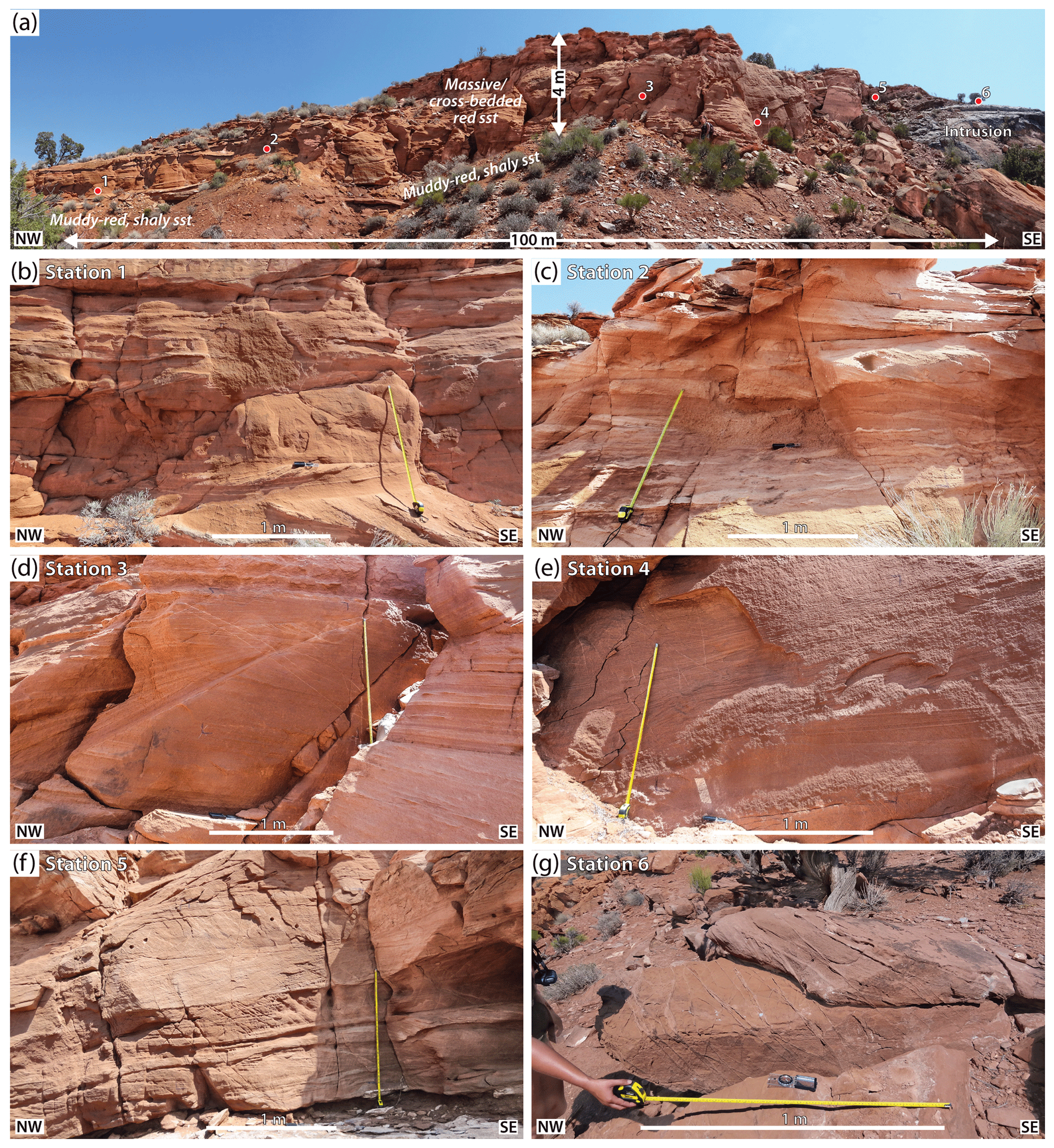
Figure 2Sampling traverse across lateral margin of the Trachyte Mesa intrusion. (a) Panoramic photograph of study area. Note red, cross-bedded Entrada Sandstone unit, and Trachyte Mesa intrusion outcropping to the right. All structural stations lie within the same cross-bedded sandstone unit. Although this unit exhibits lateral and vertical variations in sedimentary structures, attempts were made to sample rocks with similar grain size, grain rounding, and mineralogy for this study. (b–g) Overview outcrop photographs for each station.
2.1 Trachyte Mesa Intrusion
The Trachyte Mesa intrusion is a small (1.5 km2) satellite intrusion to the Mount Hillers intrusive complex in the Henry Mountains, SE Utah (Fig. 1). The Henry Mountains intrusions are Oligocene in age (31.2 to 23.3 Ma; Nelson et al., 1992). These intrusions, therefore, post-date the minor Laramide deformation observed on the Colorado Plateau. The intrusions are emplaced within an approximately 3–6 km thick section of late Palaeozoic–Mesozoic strata overlying Precambrian basement; the Trachyte Mesa intrusion was likely emplaced at a palaeo-depth of ∼3 km (Jackson and Pollard, 1988; Hintze and Kowallis, 2009).
Trachyte Mesa has an elongate, laccolithic geometry, trending NE–SW (Fig. 1b) with a thickness varying from 5–50 m (Morgan et al., 2008). The intrusion formed by the amalgamation and stacking of multiple thin (∼ 1–5 m thick) sill sheets (Johnson and Pollard, 1973; Menand, 2008; Morgan et al., 2008; Wilson et al., 2016). It is generally concordant with the Entrada Sandstone Formation, within which it is emplaced (Johnson and Pollard, 1973; Morgan et al., 2008; Wetmore et al., 2009). The best exposures of the intrusion, contact and overlying host-rock can be found on the southern end of the north-western lateral margin (Figs. 1 and 2).
2.2 The Entrada Sandstone Formation
The Entrada Sandstone Formation (part of the San Rafael Group) is Jurassic (Callovian) in age and is composed of a mixture of white cross-bedded sandstones, reddish-brown silty sandstones, siltstones, and shale beds (Aydin, 1978; Fig. 2a). The Entrada was deposited in an aeolian environment and extends over a vast area, making it the largest of the Colorado Plateau ergs (Hintze and Kowallis, 2009). Entrada Sandstone is generally quartz-dominated (Aydin, 1978), although a subarkosic composition for rock units studied around the Trachyte Mesa intrusion may be a more appropriate lithological description. Calcite is the most common cement, although siliceous and pelitic cements are abundant in some layers (Aydin, 1978).
The Entrada Sandstone, being highly porous, is the ideal lithology for the formation of deformation bands (Fig. 2) and, as a result (along with the Lower Jurassic Navajo and Wingate sandstones, also found on the Colorado Plateau and stratigraphically below the Entrada; Jackson and Pollard, 1988), has been the focus of several studies on such structures (Aydin, 1978; Aydin and Johnson, 1978, 1983; Shipton and Cowie, 2001; Fossen and Bale, 2007; Fossen et al., 2007). These Jurassic sandstones form natural fluid carrier systems and reservoirs for hydrocarbon and CO2 systems (Garden et al., 2001; Kampman et al., 2013). Although deformation bands are common throughout the Entrada Sandstone, local to the Trachyte Mesa intrusion, there appears to be a strong increase in deformation bands aligned sub-parallel to the intrusion margin. This spatial and geometric correlation leads to the proposal that these structures formed directly in response to the emplacement of the intrusion (Wilson et al., 2016).
Deformation bands in the vicinity of Trachyte Mesa generally form as conjugate sets striking roughly NE–SW and individual bands are generally narrow (<0.5 mm; Figs. 1–3), though a few wider deformation zones have developed which are cored by principal slip surfaces. In contrast, much wider deformation band clusters (>20 cm) can be found hosted by the Entrada Sandstone elsewhere on the Colorado Plateau (e.g. see Figs. 1, 7 and 9 in Fossen and Bale, 2007).
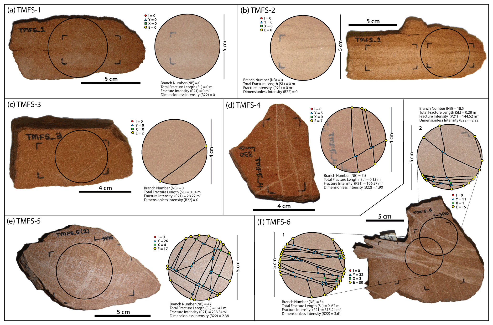
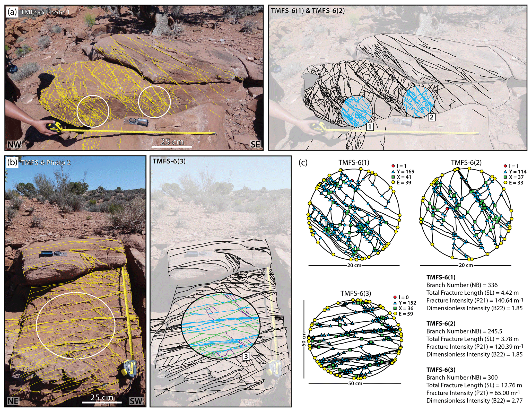
Figure 3Fracture analysis of hand specimens. (a–f) Bedding-normal cut surfaces with hand-specimen photographs showing fracture analysis circles for each structural station (note, sample numbers correspond to their respective station). Fracture analysis was carried out on freshly cut surfaces. Circular scans show the fracture network and associated I-, Y-, X- and E-nodes (for explanation of terminology see Fig. 4 and Sanderson and Nixon, 2015). Statistics show total number of branches (N), total fracture length (SL), fracture density/intensity (P21), and branch dimensionless intensity (B22).
3.1 Outcrop Traverse
Outcrop studies and rock samples were collected from a structural transect across the north-western lateral margin of the Trachyte Mesa intrusion (Figs. 2 and 3), in order to quantify the change in the network observed across the intrusion margin. The study consists of six structural stations, relatively evenly spaced, from ∼60 m outboard of the exposed intrusion margin (Station 1), and up over the monoclinal lateral margin, onto the top surface of the intrusion (Station 6) (Fig. 2). A suite of photographs was collected at each exposure (e.g. Fig. 2b–g). These photographs were subsequently used to map out the fracture networks at each station post-fieldwork (see the Appendix).
As roughly NE–SW trending deformation bands are the dominant structural orientation identified along the margin (Fig.1; Wilson et al., 2016), care was taken to ensure that the surfaces photographed, and subsequently analysed, were oriented in a similar, optimal perpendicular (NW–SE) orientation in order to sample the network most appropriately. Due to this sampling technique, results will only be appropriate for analysing fluid flow across (perpendicular to) the intrusion margin, and further analysis may be necessary to understand flow parallel to the intrusion margin. It is acknowledged that by only carrying out studies in one orientation we are invoking an orientation bias into our results. However, choosing sections at a high angle to the main orientation of the band intersections should minimise the bias in both the geometrical and topological parameters.
3.2 Sample Collection
A selection of rock samples was collected at each structural station (Fig. 3) in order to carry out hand-specimen and thin-section (i.e. petrological, porosity and microstructural) studies. Samples were oriented in the field in order to enable thin sectioning in a similar vertical, NW–SE oriented plane to the outcrop photograph/scan surfaces. Ensuring that similarly orientated sample areas are studied at all scales increases the chances of sampling the same fracture systems (i.e. NE–SW trending fracture networks) as observed in outcrop, and thus the resulting scalar statistics should be more appropriate.
3.3 Analysis Methods
Various analytical techniques have been proposed for the investigation of fracture networks (e.g. Walsh and Watterson, 1993; Berkowitz, 1995; Adler and Thovert, 1999). In this study the methods outlined by Sanderson and Nixon (2015) and Procter and Sanderson (2018) have been applied. The method was described in detail by Sanderson and Nixon (2015), and only a brief summary is given here. The basic principle is outlined in Fig. 4, and comprises the mapping of a 2D fracture network, measuring fracture (or branch) lengths and quantities, and node counting (e.g. Fig. 5).
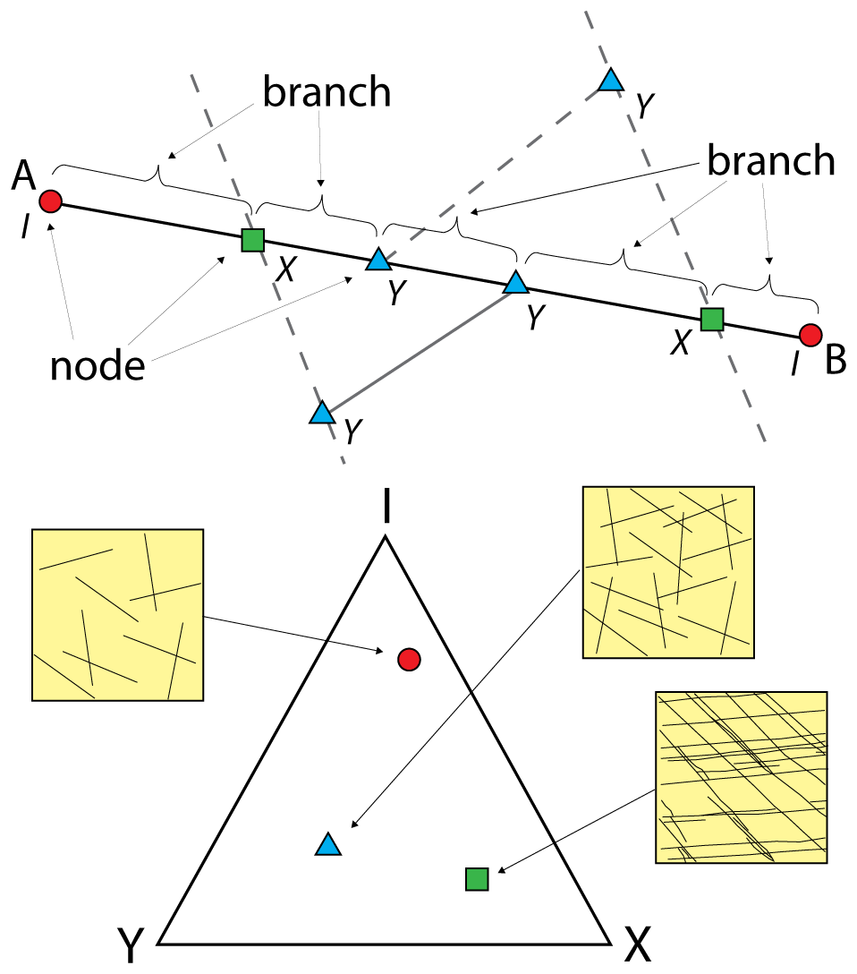
Figure 4Schematic image outlining the principal method applied for fracture analysis (Sanderson and Nixon, 2015). Branches and nodes are shown on fracture trace (A–B): I-nodes (red circles); Y-nodes (blue triangles); X-nodes (green squares). Proportions of I-, Y- and X-nodes may be plotted on a ternary plot to visualise different fracture network types (after Manzocchi, 2002).

Figure 5Example of fracture analyses undertaken at different scales in this study, sample TMFS-5. (a) Outcrop photograph with superimposed fracture analysis circle showing the fracture network and associated I-, Y-, X- and E-nodes. (b) Hand specimen analysis (see Fig. 3). (c) Whole thin-section photograph (taken using flatbed scanner) and plain-polarised light (PPL) photomicrograph. Optical microscopy petrographical, porosity and microstructural analyses were carried out on thin sections cut from each hand specimen. Sections were impregnated with blue resin to highlight porosity.
3.3.1 Deformation Band Network Map
Using the outcrop photographs, deformation band networks were mapped to the highest level of detail attainable from the image resolution. Areas were then selected in order to sample the networks at each site. In areas of more heterogeneous deformation, multiple areas were sampled at different scales (ranging from 20–100 cm diameter circles) in order to capture the variability. Circular scan-lines/areas were used rather than squares as these provide the least orientation bias, with an equal likelihood of sampling any given fracture orientation on a 2D surface (Mauldon, 1994; Rohrbaugh et al., 2002; Procter and Sanderson, 2018).
3.3.2 Measuring Lengths and Quantities
For each sample circle, the total number of deformation bands and total band length were recorded. In addition, the total number of branches (i.e. segments between intersecting deformation band points or nodes) was also determined. Sanderson and Nixon (2015) argued that preference should be given to the use of branches as it is often difficult to recognise an individual, continuous fracture trace within a deformation band network, whereas branches are uniquely identifiable. Furthermore, as exposures and sampling areas are of finite size, many deformation bands extend beyond the sample area. Therefore, the frequency and length of deformation bands will be subject to sampling bias (Riley, 2005). By contrast, the length of branch lines is likely to be less censored, thus reducing this sampling bias issue.
Using sample area, total number of deformation bands (or branches) and total deformation band (branch) length, a number of fracture network characteristics can be defined. These include: frequency (total number/area); intensity (total length/area); spacing (the inverse of intensity, i.e. area/total length); characteristic fracture length (mean length; total fracture length/ total number of deformation bands); and dimensionless intensity (multiplying fracture intensity by the characteristic length). Details on the derivation of these terms were provided by Sanderson and Nixon (2015).
3.3.3 Node Counting
A given deformation band network consists of lines, nodes and branches (Figs. 4 and 5a–b). As outlined above, lines will consist of one or more branches, with nodes (i.e. fracture intersections) at either end of each branch. Three main types of nodes exist: I-nodes (isolated fracture terminations within the host rock); Y-nodes (where one fracture terminates against another); and X-nodes (where two deformation bands cross-cut one another). Within a sample area, a fourth type of node may also be recorded, where deformation bands intersect the outer perimeter of the sample area (termed E-nodes; Sanderson and Nixon, 2015). As discussed by Procter and Sanderson (2018), combining node counting with a measurement of intensity (usually P21 – trace length per unit area) provides a very efficient way to characterise both the geometry and topology of fracture networks.
The proportion of I-, Y- and X-nodes have been used by various authors to characterize a fracture network (e.g. Manzocchi, 2002; Mäkel, 2007) and the results plotted on a triangular diagram (Fig. 4). As the relative proportion of nodes will remain unchanged by any continuous transformations (i.e. scale changes and strains), this is termed a topological classification (Sanderson and Nixon, 2015).
3.4 Thin section and porosity analysis
Optical microscopy petrographical, porosity and microstructural analyses were carried out on thin sections cut from each hand specimen (e.g. Fig. 5c). Sections were impregnated with blue-dyed plastic resin in order to highlight porosity. Both compositional percentages were visually estimated using percentage estimation comparison charts (Bacelle and Bosellini, 1965; Tucker, 2001), while quantitative analyses of porosity percentages were attained using the image analysis software package ImageJ (Fig. 6; Schneider et al., 2012; Heilbronner and Barrett, 2014).
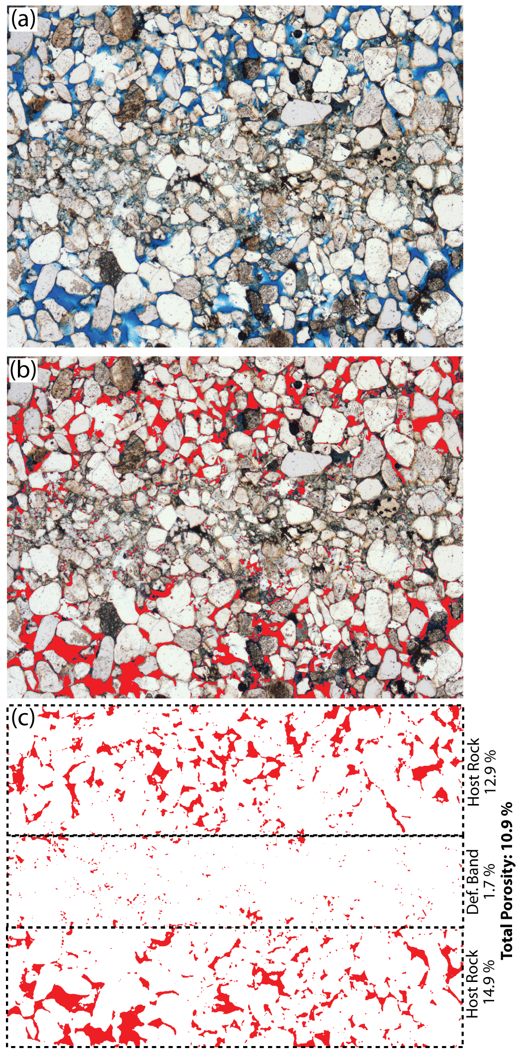
Figure 6Quantitative determination of porosity percentages using ImageJ. (a) Sections were impregnated with blue-dyed plastic resin in order to highlight porosity. (b) Image analysis using ImageJ to select areas (red) containing blue dye. (c) Percentage areas (porosities) can then be calculated for both whole section and selected areas (e.g. host rock vs deformation band). Note the substantially lower porosity and smaller pore size within the deformation band.
4.1 Fracture Analysis
Six structural stations were analysed across an approximately 100 m-long transect over the north-western intrusion margin (Fig. 2 and Appendix). In order to maximise the area sampled at each scan station, data from multiple scan circles have been aggregated. Note, where scan circles overlap, data have been omitted from the totals to avoid duplication, e.g. at Station 1 where all smaller scan circles lie within the larger circle. Results are summarised in Table 1 and Fig. 7. The values for Station 2, and to a lesser extent Station 1, are based on relatively few measurements. Procter and Sanderson (2018) recommended at least 30 nodes, so the data from Station 2 (7 nodes) should be considered unreliable, compared to the other stations where the number of nodes varies from 24 (Station 1) to 847 (Station 5).
Table 1Summary table showing total values for each structural station. Total values do not include hand specimens due to their small size making estimates of frequency and intensity unreliable, though trends for samples do match those for outcrops in this study. For details on individual scan circles see the Appendix.
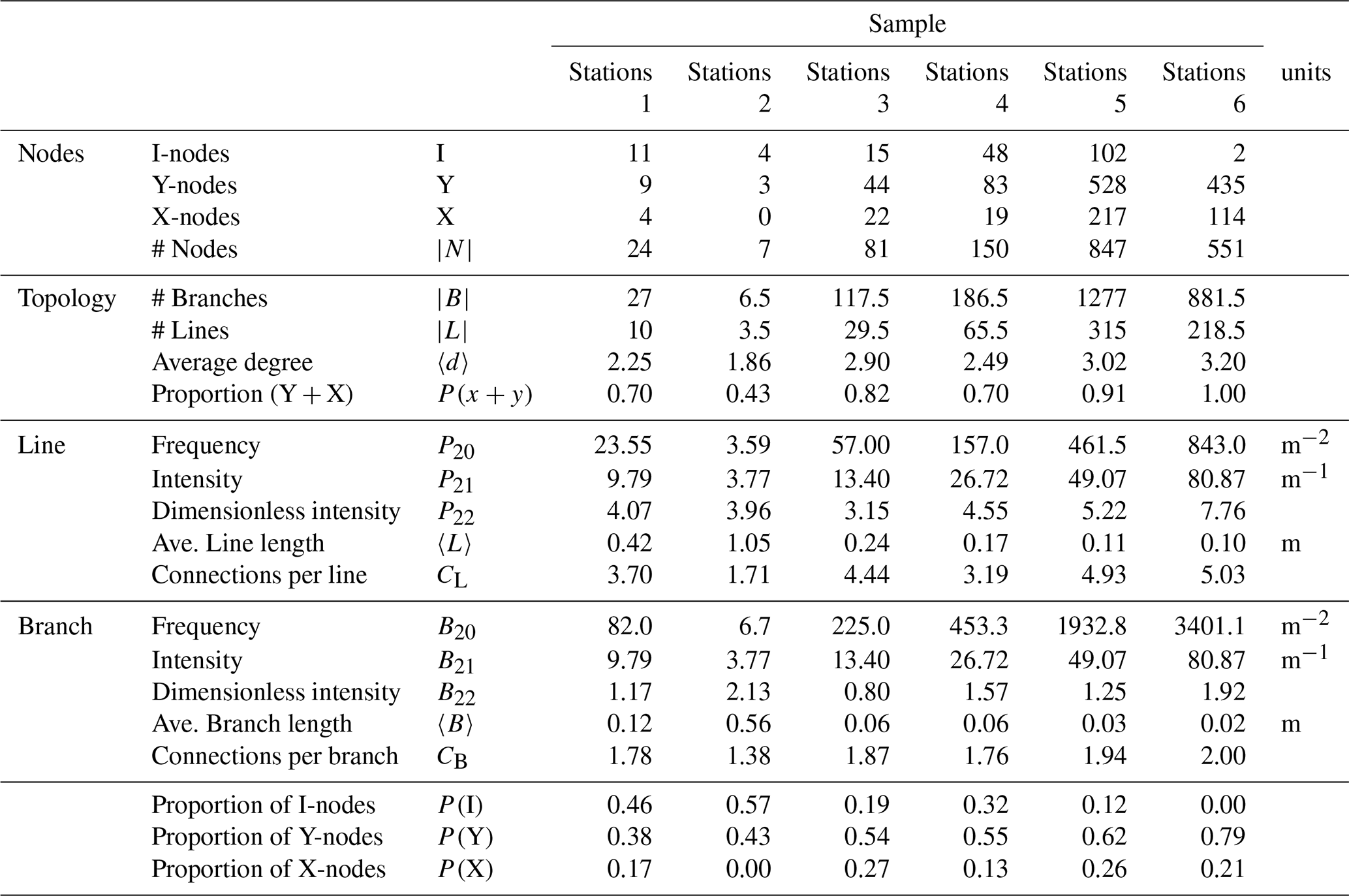
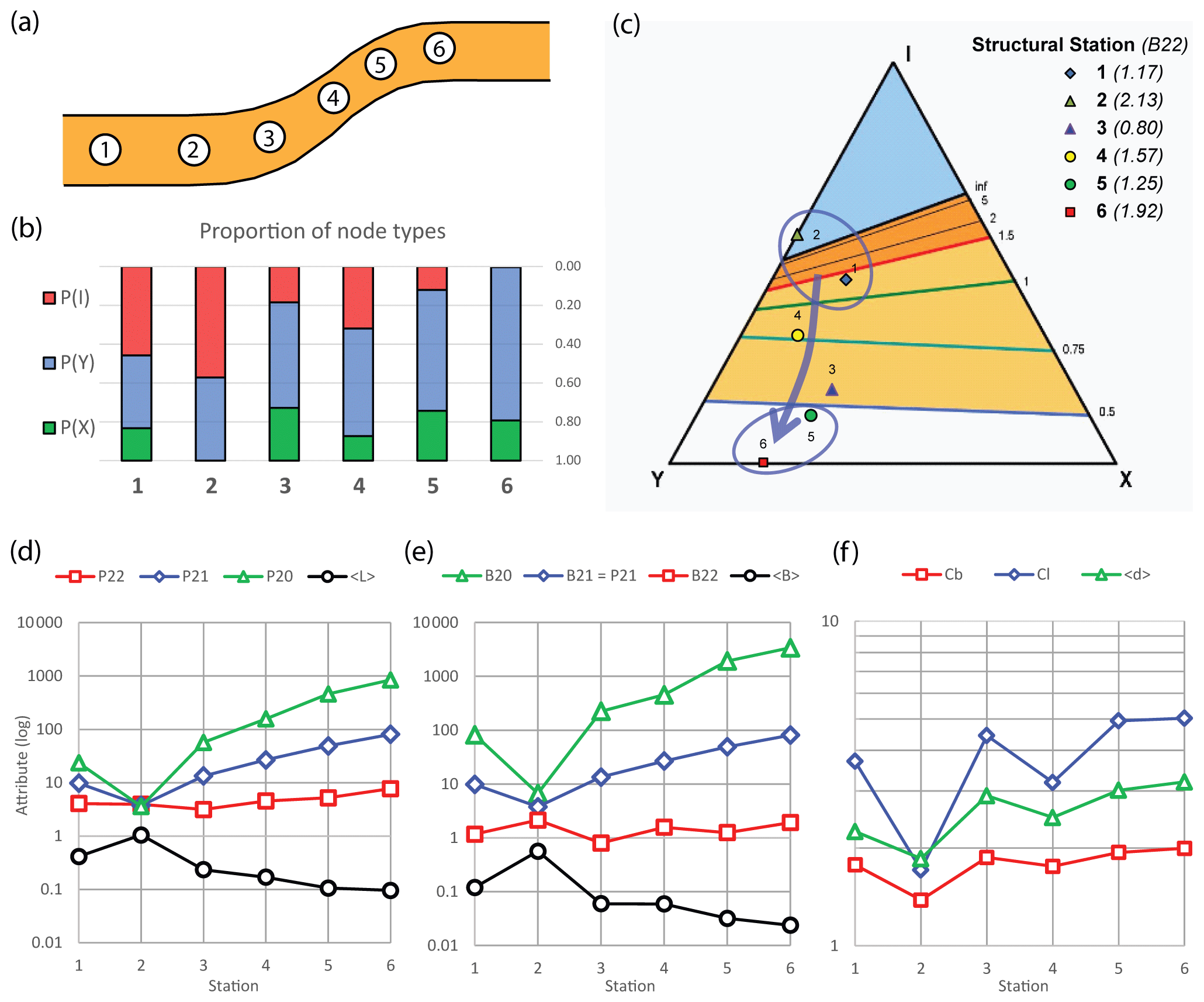
Figure 7Nodal and fracture analysis results. (a) Schematic diagram showing relative location of each structural station across the monoclinal intrusion margin. (b) Bar chart showing spatial variation in nodal populations. (c) Triangular plot showing ratio of I-, Y- and X-nodes for total values for each station. Contours represent the branch dimensionless intensity (B22) of a network with that nodal topology when it is at the percolation threshold (i.e. the limit or threshold at which the network is “unconnected”/“connected”). If the network has a higher B22 than in the contour plot then the network is considered connected; conversely if lower it is considered unconnected. As the B22 values for Stations 1 and 2 (see Table 1 and values in key) are below the contour values, these deformation band networks are clearly unconnected, whereas Stations 4, 5 and 6 are well above the contour values and thus may be considered well connected. For more details on the triplot template, see Sanderson and Nixon (2018). (d–f) Summary plots showing the log of various fracture attributes at each station (see Table 1 for values). 〈L〉: Mean line length (m; total line length/number of lines); P20: line frequency; P21 (m−2; number of lines/sample area): line intensity (m−1; total line length/sample area); P22: line dimensionless intensity (multiplying line intensity by the mean length); 〈B〉: Mean branch length (m; total branch length/number of branches); B20: branch frequency (m−2; number of branches/sample area); B21: branch intensity (m−1; total branch length/area); B22: branch dimensionless intensity (multiplying branch intensity by the mean length); 〈d〉: average degree of nodes (the number of branches that meet at a node); CL: connections per line; CB: connections per branch.
Nodal populations for each station were recorded (Table 1, Fig. 7b) and plotted on triangular diagrams (Fig. 7c; after Manzocchi, 2002). The outcrops studied show a clear dominance of I- and Y- nodes (Fig. 7), although the proportion of these nodes varies across the transect (Fig. 7b). Structural stations more distal to the intrusion (i.e. Stations 1 and 2) show approximately equal proportions of I- and Y-nodes (Fig. 7). The proportion of I-nodes decreases through Stations 3 to 4, where Y-nodes become dominant with proximity to the intrusion. At Stations 5 and 6 overlying the intrusion, I-nodes are negligible, and the nodal populations are dominated by Y- and X-nodes. These results reflect the overall increase in connectivity of the conjugate deformation bands observed at the intrusion margin (Morgan et al., 2008; Wilson et al., 2016).
The abundance of deformation bands increases with proximity to the intrusion (Fig. 7d). The frequency of branches (B20, Fig. 7e) increases from <100 m−2 in Stations 1 and 2 to ≫1000 m−2 above the intrusion (Stations 5–6). This is accompanied by an increase in branch intensity (B21) from ∼10 to 100 m−1, despite a significant reduction in the length (〈B〉). This increase in intensity is accompanied by a decrease in length (〈B〉 in Fig. 7e), and this is also seen in the fracture data (〈P〉 in Fig. 7d). The net result is that there is little change in the dimensionless intensities of the branches () and traces (), which can be interpreted in terms of the networks mainly becoming more intense towards the intrusion, but with their dimensionless geometry or “pattern” remaining fairly scale-invariant (but see comments on topology, in following paragraph).
The change in node types indicates a change in topology across the transect (Fig. 7b). Stations 1 and 2 plot in the upper region of the I-Y-X triangle (Fig. 7c), which is where “tree-like” networks, with few branches enclosing blocks typically develop (e.g. Fig. 2b, c), whereas the other stations are more dominated by connected nodes (Y and X), typical of networks with lots of branches and deformation bands that enclose many small blocks (as seen in Figs. 3e, f and 5a, b). These topological changes can be monitored by several key parameters (Fig. 7f). The connections per line (CL) increase to values of ∼5 above the intrusion, and such values typify highly connected networks, although Sanderson and Nixon (2018) noted that CL for connected Y-dominated networks is generally lower. They favoured the use of the number of connections per branch (), which attains values close to 2 above the intrusion. The average degree 〈d〉 of the nodes (i.e. the number of branches that meet at a node) increases from 〈d〉≈2, typical of trees, to 〈d〉≈3, typical of many joint networks (e.g. Procter and Sanderson, 2018). Taken together, these topological parameters indicate greater connectivity of the deformation band networks as the intrusion is approached.
4.2 Microstructural Analysis
Thin section analysis of outcrop samples further shows a significant increase in deformation and fracture intensity with proximity to the lateral intrusion margin. Outboard (∼ 40–60 m; Stations 1 and 2) from the lateral intrusion margin, samples show little sign of deformation and moderate porosity (10 %–15 %; Figs. 8 and 9). Sample TMFS-1 – assumed to represent the host rock – is a well-sorted, medium- to fine-grained (∼250 µm) sandstone, dominated by quartz (> 80 %) and feldspar (plagioclase and microcline; Fig. 9a). In its seemingly undeformed state, using the classification of sandstones of Pettijohn et al. (1987), the host rock can be classified as a subarkose. Haematite can be seen coating quartz grains, whilst there is some sericitisation of feldspars due to alteration. No distinct cross-laminations are apparent when examining the thin section under the microscope, although some layering is visible when viewing the whole thin section (Fig. 8a). The sample shows relatively high porosity, however zonal variations are apparent; an average porosity of 11.5 %, rising to 14 % in places (Fig. 8b). The sample is relatively poorly cemented, however large patches of poikilotopic calcite spar (Fig. 9a, b) significantly reduce the overall porosity (>5 % porosity reduction). No deformation bands have been identified in sample TMFS-1. However, the sandstone is relatively well compacted, with embayed contacts apparent at grain contacts.
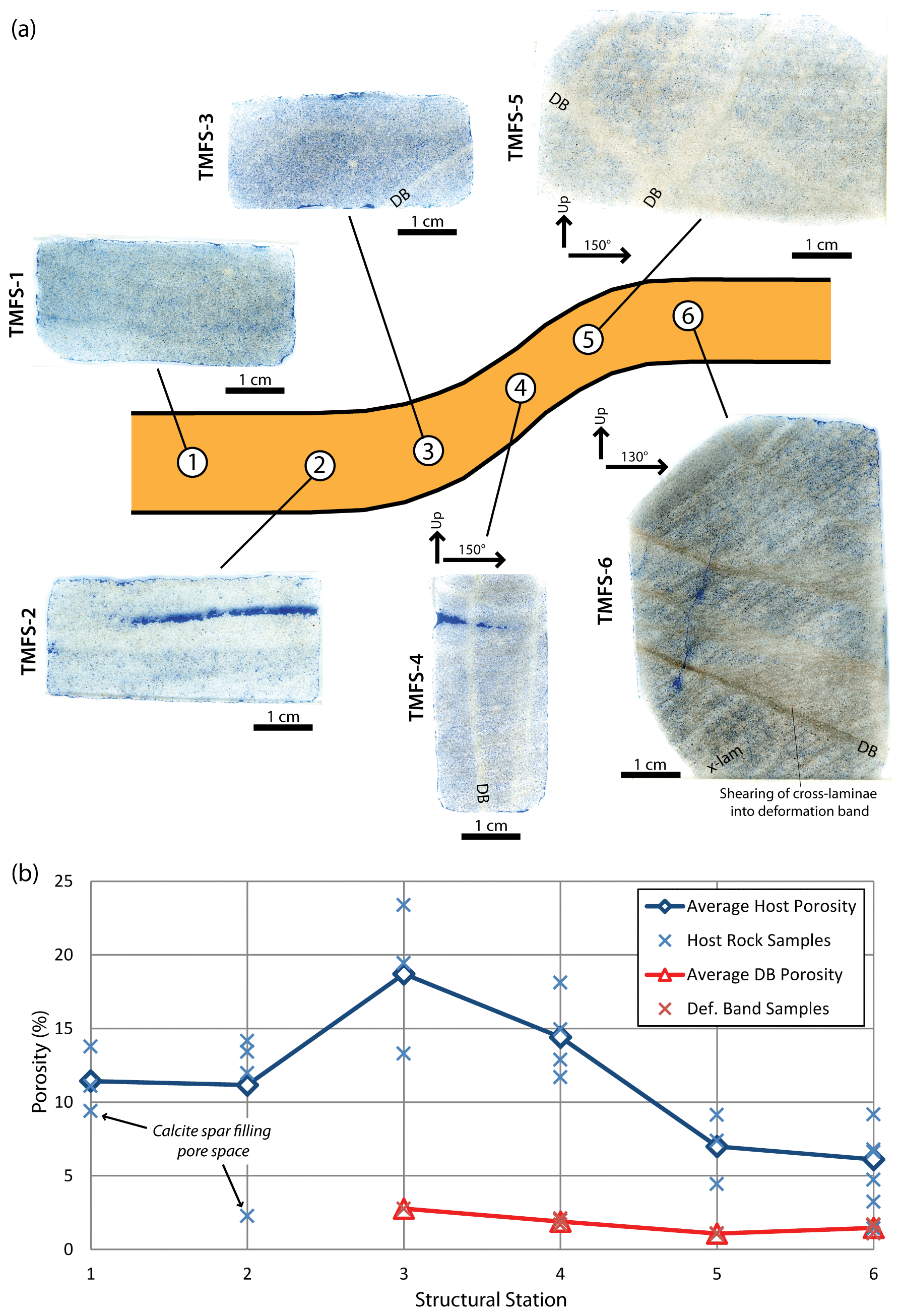
Figure 8Porosity variability across the intrusion margin. (a) Whole thin-section photographs (flatbed scans) for each structural station. Blue dye denotes porosity in each sample. (b) Plot showing variability in porosity observed in this study for each station. Porosity percentages were calculate using the image analysis software package ImageJ as shown in Fig. 6. Note, a similar porosity reduction trend has been observed previously (see Fig. 8 in Morgan et al., 2008). DB: Deformation Band; X-lam: Cross-lamination.
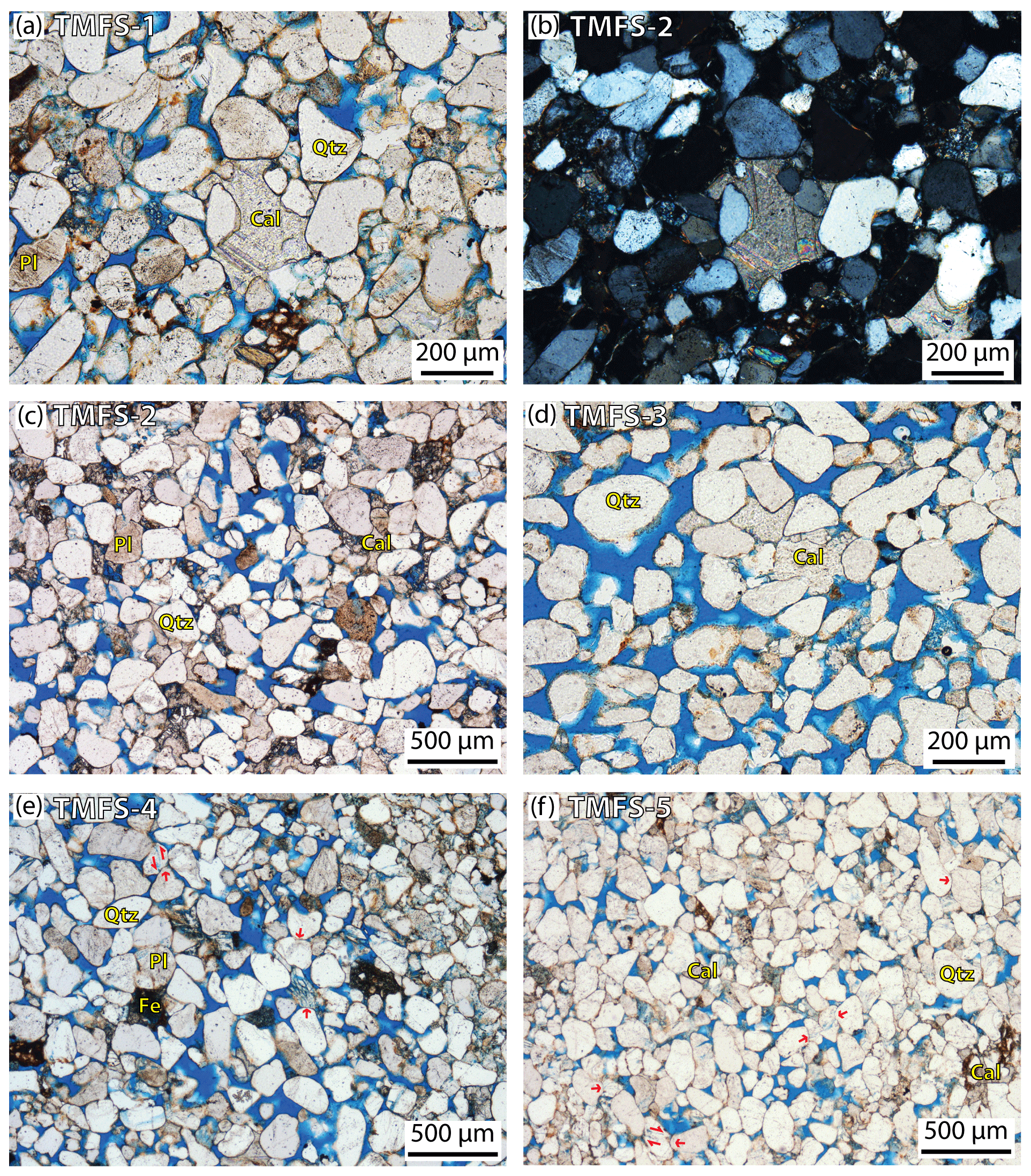
Figure 9Thin section photomicrographs showing host rock composition structure and porosity. Note overall decrease in porosity (blue dye staining) and increase in deformation from sample TMFS-1 through to TMFS-5. (a) Undeformed host rock sample TMFS-1 viewed under plane polarized light (ppl) showing well-sorted subarkose host rock, variable porosity ∼ 9.4 %–13.8 % due to patchy calcite spar (note large poikilotopic calcite spar in centre of section); (b) Same section as (a) viewed under cross polarized light (xpl); (c) Undeformed host rock sample TMFS-2 (viewed in ppl) showing a well-sorted subarkose host rock, total porosity ∼12 %, and patchy calcite spar; (d) High porosity zone (23.4 %) in sample TMFS-3 (ppl); (e) Deformed host rock sample TMSF-4 (ppl), 16.4 % porosity, note the pressure solution, embayed contacts and intragranular microcracks and microfractures (both tensile and shear fractures observed) in multiple quartz grains (see red arrows for examples); (f) Deformed host rock sample TMFS-5 (ppl) showing markedly reduced porosity (9.1 %), further deformation structures (intragranular fractures, embayed contacts and pressure solution), apparent grain size reduction and tighter pack in of grains. Cal: Calcite spar; DB: Deformation Band; Fe: Iron staining; Pl: Plagioclase Feldspar; Qtz: Quartz. Red arrows highlight zones of pressure solution, embayed contacts, and microfractures. Porosity values from ImageJ image analysis.
TMFS-2 appears to sample a slightly coarser-grained bed within the tracked sandstone unit (Fig. 2). Laminations are clearly visible at both the hand-specimen and thin-section scale (Figs. 3b and 8a). Thin-section analysis shows a well-sorted sample with similar subarkose composition to TMFS-1. Sub-rounded grains suggest that this sandstone is relatively mature. Large patches of poikilotopic sparry calcite are again present (Fig. 9c). Similar to TMFS-1, this sample also shows no visible deformation bands. TMFS-2 exhibits similar porosities to that of TMFS-1, with an average porosity of ∼11.2 % (Fig. 8). Again calcite cementation reduces porosity significantly across the whole sample, with porosity for some laminations falling to <3 %.
Approaching the lateral intrusion margin (∼20 m), sample TMFS-3 retains a high porosity of up to 23 % (average 18.7 %; Fig. 8), again displaying patchy poikilotopic calcite spar cementation (Fig. 9d), though less than in TMFS-1 and -2. The sample exhibits minor deformation, though only one deformation band was sampled. This band is not well developed with distributed microcracking and minor cataclasis (Fig. 10a). The deformation band displays significant porosity reduction (2.7 % porosity in the deformation band zone), with the majority of the porosity loss appearing to be due to the development a finer crystalline, equant calcite microspar cement (Fig. 10a).
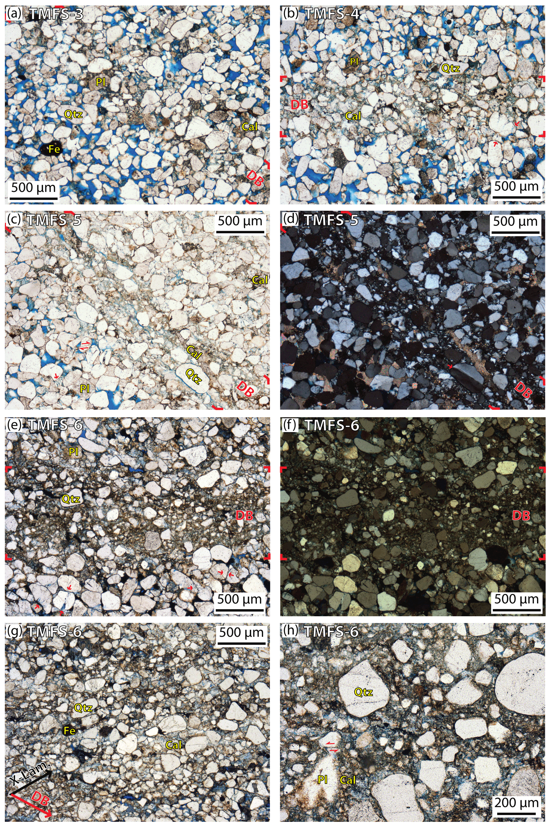
Figure 10Thin section photomicrographs showing deformation band structure and porosity (edges of deformation bands highlighted in by red markers at edges of image). (a) Poorly developed deformation band in sample TMFS-3 (viewed in ppl) showing minor cataclasis (microcracks and fractures), embayed contacts and an increase in calcite cementation within the deformation band. Note the marked decrease in porosity within the host rock (13 %–23 %) and the deformation band (2.8 %); (b) Deformation band in sample TMFS-4 (viewed in ppl) showing intragranular microcracks and transgranular fractures (red arrow), grain size reduction, and an increase in calcite cementation within the deformation band (host rock porosity 12.9 %–14.9 %, deformation band porosity 1.7 %; Fig. 6); (c, d) Deformation band in sample TMFS-5 viewed under ppl (c) and xpl (d), (host rock porosity 7.4 %, def. band porosity ∼1.1 %). Cataclastic fabrics within the deformation band includes angular smaller grains (grain size reduction), intragranular microcracks and microfractures, and increase in calcite cementation within the deformation band. Note, in xpl (d) the subgrain boundary within large quartz grain sub-parallel to band orientation, as well as microcracks, transgranular fractures and undulose extinction in some quartz grains outside the defined deformation band; (e, f) Deformation band in sample TMFS-6 viewed under ppl (c) and xpl (d), (host rock porosity 3.2 %–4.7 %, deformation band porosity ∼1.6 %). Deformation band shows well defined cataclastic fabrics (angular smaller grains, intragranular microcracks and microfractures, sheared and rotated grains) and an increase in calcite cementation. Note, the many strained grains (microcracks, transgranular fractures, undulose extinction, rotated grains and embayed contacts) outside the defined deformation band; (g) Sample TMFS-6 (viewed in ppl) showing deformation band cross-cutting a cross lamination within the sandstone (see annotation showing orientation of DB relative to laminae). Note the dominance of small angular grains in the section, reflecting grain fracturing within deformation band. (h) Sample TMFS-6 (viewed in ppl) showing microporosity with deformation band, note clean angular contacts to quartz grains and less distinct (“fuzzy”) grain boundaries to feldspar grains. Angular shear fracture in quartz grain highlighted with red arrows. Cal: Calcite spar; DB: Deformation Band; Fe: Iron staining; Pl: Plagioclase Feldspar; Qtz: Quartz; X-Lam: cross-lamination. Red arrows highlight zones of pressure solution, embayed contacts, and microfractures. Porosity values from ImageJ image analysis.
Moving onto the intrusion margin, sample TMFS-4, background (host rock) porosity is variable from lamina to lamina, although the average remains relatively high at 14.4 % (Figs. 8, 9e). The host rock shows evidence for strain, with grains exhibiting embayed contacts, intragranular microcracking and transgranular fractures (Fig. 9e). TMFS-4 samples three discrete (∼1 mm wide) deformation bands (Figs. 8a and 10b). Microstructural analysis of these bands shows evidence for cataclasis (distributed microcracking and grain-size reduction; Fig. 10b). The grain size of the host rock is medium to coarse (>250 µm), while within deformation bands this is significantly reduced (<50 µm). Although porosity is considerably reduced, microporosity (1.7 %–3.1 %) is still apparent within deformation bands. Calcite locally fills pores within the deformation bands, accounting for some of the porosity reduction (Fig. 10b).
Immediately above the lateral intrusion margin, sample TMFS-5 (Fig. 8a) displays significant deformation zones. Background (host rock) porosity is lower than the less deformed samples described above (average 7.0 %; Figs. 8b, 9f). This is due to greater compaction, as evidenced by the higher proportion of interlocking (more tightly packed) grains, embayed contacts and possible pressure solution with sutured grain contacts and intragranular fractures (Fig. 9). Calcite cementation within the background rock is patchy, with calcite spar accounting for only 2 %–3 % of porosity reduction. Sampling several deformation bands, these appear more diffuse (up to 1 cm wide; Figs. 8a and 10c–d) than those sampled in TMFS-4. Although not well-established, distinct slip zones may be identified within deformation bands. Microporosity within the deformation bands is extremely low (∼1.1 %; Fig. 8b). Clear cataclasis and associated grain-size reduction (note abundance of angular grains that are reduced in size with respect to subrounded grains in the host rock) can be seen within the bands (Fig. 10c–d). Although larger grains are still present within the deformation bands, these show evidence for significant microfracturing and early development of sub-grain boundaries (Fig. 10d).
Passing over the upper hinge zone of the monoclinal intrusion margin, sample TMFS-6 (Fig. 8a) shows a clear system of moderately-dipping cross-laminations. Again, a subarkose composition is apparent (quartz grains with lesser plagioclase- and microcline-feldspar). Embayed contacts are visible showing pressure solution/dissolution and focused intragranular fractures (e.g. Fig. 10e). Background porosity is significantly reduced in TMFS-6 compared to the other 5 samples, at 3 % to 9 % (average porosity 6.1 %; Fig. 8b). This is largely due to a combination of compaction, cataclasis and greater calcite cementation (Fig. 10e–h). Multiple diffuse and discrete, anastomosing deformation bands are identifiable (Figs. 8a and 10e–h). Microporosity within the deformation bands is <1.5 % (Fig. 10h), again the result of cataclasis (grain-size reduction), compaction and cementation. Shearing of cross-laminations into deformation bands can be clearly seen (Figs. 8a and 10g). Within deformation bands larger quartz and feldspar grains are still evident within a finer-grained cataclastic matrix (angular small grains). However, some of these larger grains have “fuzzy” grain boundaries which may reflect cataclasis along the boundary, while other grains show clear sub-grain boundaries parallel to deformation band orientations (Fig. 10e–h). Weakly developed slip planes are apparent within deformation bands, while at a grain-scale, shear can also be identified (Fig. 10h).
5.1 Fracture Intensity and Topology Variations Across the Margin
A clear increase in fracture abundance can be observed across the intrusion margin. The quantitative analysis of fracture attributes, such as intensity, frequency and dimensionless intensity, increase progressively across the intrusion margin (Fig. 7). In addition, analysis of nodal populations highlights the topological change across this same area. As fracture frequency and intensity increase onto the intrusion, this is accompanied by an increase in Y (and to a lesser extent X) nodes. Manzocchi (2002) and Sanderson and Nixon (2018) both linked changes in nodal populations to critical dimensionless intensity, and percolation thresholds, using stochastic models.
Figure 7 shows the nodal distributions for this study overlain on contoured triplots defining lines of critical branch dimensionless intensity (B22). These contours represent the B22 of a network with that topology when it is at the percolation threshold (i.e. the limit or threshold at which the network is “unconnected”/“connected”). If the network has a higher B22 than that for its position in the contour plot then the network is considered connected; conversely if lower it is considered unconnected. In Fig. 7 it is clear that the fracture networks at stations above the intrusion margin (i.e. Stations 4–6) are all highly connected, with B22 values well above the contour of critical branch dimensionless intensity within which the nodal populations plot (cf. Sanderson and Nixon, 2018). In contrast, the fracture networks at scan stations outboard of the intrusion (Stations 1 and 2) are clearly not connected; with B22 values well below the contours of critical branch dimensionless intensity. The B22 value for TMFS-3, located ∼20 m away from the mapped intrusion margin, when considering the nodal population triplot, suggest that the system is connected; however, the total value lies close to that of the percolation threshold.
Nodal populations were also acquired at the hand-specimen scale (Fig. 3 and Appendix). Similar topological trends are apparent from these hand-specimen samples; however, values appear more extreme at both end members (i.e. B22=∞ at Stations 1 and 2 where samples contained no deformation bands, and B22>2 at Stations 4 and 5 overlying the intrusion) compared to the outcrop-scale studies. These extreme end-member values may simply be due to sampling bias as part of the sample collection and, had more samples been collected at each station, it is likely that total and average values would align better with those obtained at outcrop.
Figure 11 shows schematic 3D block diagrams which compare the distribution of deformation band structures across the Trachyte Mesa intrusion to forced folds above a normal fault (Ameen, 1990; Cosgrove, 2015). The variations in the deformation band network geometry seen across the Trachyte Mesa intrusion margin (Wilson et al., 2016) are very similar to those in the model for forced folds above a normal fault. The increase in fracture intensity, frequency and dimensionless intensity is also consistent with this model, with deformation increasing across the forced fold. Offsets are dominantly extensional, consistent with the forced-fold model.
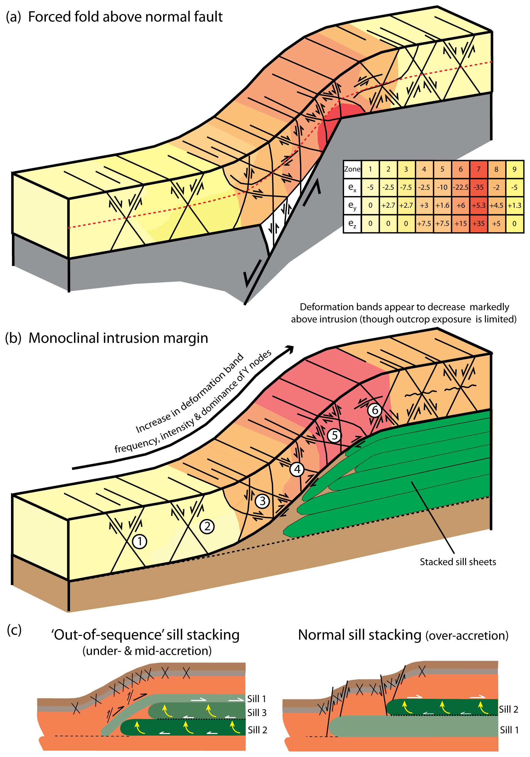
Figure 11Schematic 3D block diagrams and cross sections comparing the distribution of deformation structures. (a) A forced fold above a normal fault (modified after Ameen, 1990 and Cosgrove, 2015). (b) Deformation bands across the Trachyte Mesa intrusion (this study). (c) Cartoon showing varying deformation styles and distribution in relation to the order of sill sheet stacking (Wilson et al., 2016). In (a) the fold is divided into zones (see inset table) depending on the level of strain normal (ez) and parallel to the layer (ey parallel to the fold hinge and ex normal to it). Note: extension is negative and contraction positive. Coloured zones highlighted in (b) are solely for visual purposes and do not correspond to the strain zones defined in (a).
The analogy to the growth of a normal fault is viable due to the mode of emplacement of the Trachyte Mesa intrusion through vertical stacking of sill sheets (Morgan, 2008; Wilson et al., 2016), which represent the uplifted footwall block. As the intrusion grows in size (by the incremental addition of sill sheets) this drives the shear localisation of deformation similar to that of a propagating normal fault (e.g. Ballas et al., 2015). The model assumes a two-phase growth mechanism for individual sheets, whereby the sill sheet propagates laterally as a thin layer and then vertically inflates (Hunt, 1953; Corry, 1988; Wilson et al., 2016). The vertical inflation phase of each individual sheet would therefore mimic individual fault growth/slip events on a normal fault scarp. However, as highlighted by Wilson et al. (2016), the order of stacking of sill sheets (over-, under-, mid-accretion; Menand, 2008) can significantly impact the style of syn-emplacement deformation within the overlying host-rocks (Fig. 11c). The transect in this study samples a section of the intrusion margin which displays out-of-sequence (i.e. under- and mid-accretion; Menand, 2008) stacking, which leads to a broader monoclinal margin. In contrast, in a stepped margin (resulting from over-accretion of sill sheets), a more complex zonal variability in the fracture network and topology may be observed, rather than the gradual change seen for the monoclinal margin in this study.
Due to a lack of Entrada host rock exposures across the top surface of the intrusion, the transect in this study does not extend a significant distance onto the intrusion top surface, in order to sample the deformation style and intensity away from the monoclinal margin. There are, however, a limited number of host rock exposures distributed across the wider intrusion top surface. These do not appear to exhibit the intensity of deformation bands observed in this study, though sandstone porosities do appear reduced (based on field observations at outcrop, but not sampled), suggesting that the style of deformation over the intrusion top surface differs markedly from that along the intrusion margin (e.g. Fig. 9b).
5.2 Porosity and Microstructural Variations
Microstructural analysis of deformed samples shows dominantly brittle deformation with cataclastic flow and compaction occurring within deformation bands. Despite significant porosity reduction from undeformed host rock (typically 10 %–23 %) to within deformation bands, micro-porosity of <2 % is still apparent within deformation bands. This porosity reduction is largely the result of cataclasis and compaction; however, calcite cementation also plays a significant role in many of the sampled deformation bands. This order of magnitude change in porosity is consistent with many previous deformation band studies (e.g. Eichhubl et al., 2010; Sun et al., 2011; Ballas et al., 2015).
Deformation bands outboard of the intrusion margin (i.e. TMFS-1 to -3) appear to show dominantly compaction related deformation, with minor cataclasis (Figs. 8 and 9). These would therefore be best categorised as pure and/or shear-enhanced compaction bands (PCBs and SECBs; Eichhubl et al., 2010; Ballas et al., 2015). As you move closer to the intrusion margin, more embayed contacts and evidence for pressure solution are observed (e.g. TMFS-4; Fig. 9). This may be an indication of shortening and an increasing margin perpendicular stress with proximity to the intrusion. Deformation bands in samples collected from localities above the intrusion (i.e. TMFS-5 and -6) show significantly more evidence for cataclasis and grain shearing (Fig. 10), highlighting the strain localisation in this domain (Fig. 11b). Although strain localisation is evident, none of the deformation bands analysed in this study exhibit well-defined principal slip surfaces or fault cores; such deformation band fault zones are, however, more common in areas of the intrusion margin where sill sheets are stacked in a normal sequence and where strain is localised at individual sill-tip terminations (Fig. 11c; Wilson et al., 2016).
As discussed by Ballas et al. (2015), these different deformation band types may each have subtle differences in how they impact the overall permeability and flow pathways within the sandstone. PCBs and SECBs may reduce the local permeability by two orders of magnitude, however the lack of cataclasis may negate these bands from forming barriers to flow (Rotevatn et al., 2013), but may influence flow pathways (Sternlof et al., 2006). In contrast, cataclastic bands will also reduce the local permeability by two, or more, orders of magnitude (Ballas et al., 2015), but may also significantly impede flow due to additional fabric anisotropy, forming barriers (e.g. Ogilvie et al., 2001) and significantly impacting flow pathways (Taylor and Pollard, 2000; Soliva et al., 2013). Therefore, in addition to the topological variations outlined in Fig. 7, understanding the deformation band type is also an important consideration.
In addition to porosity reduction due to deformation bands, a reduction in host-rock porosity is apparent within samples TMFS-5 and TMFS-6, from sandstone beds overlying the intrusion (9 %–23 % in samples TMFS-1 to -3 compared to 4 %–9 % in samples TMFS-5 and -6). This reduction appears to be the result of greater compaction of grains and an increase in cementation. The increased cementation observed in samples TMFS-5 and -6 (as well as the presence of calcite spar in the more distal outcrops) could be related to the circulation of warm fluids around the intrusion during emplacement. As the solubility of calcite decreases with increasing temperature, the heat introduced by the intrusion could facilitate precipitation of calcite from surrounding groundwater of appropriate composition. This is consistent with the observed porosity reduction and thinning of beds over the monoclinal intrusion margin observed by Morgan et al. (2008).
In addition to these various host rock deformation structures impacting fluid flow, of course by far the most significant impact on the reservoir scale permeability framework is the intrusion itself. Permeability within the intrusion is extremely low and so regional fluid flow pathways will first be influenced by the easiest route around the intrusion, which will be influenced not only by the distribution and connectivity of deformation structures discussed in this study, but also by the permeability of the surrounding undeformed host rock.
5.3 Wider Implications
Shallow-level intrusions are a common feature of many hydrocarbon basins, including: the NE Atlantic margin (e.g. Malthe-Sørrenssen et al., 2004; Hansen and Cartwright 2006); West of Shetland (e.g. Rateau et al., 2013; Gardiner et al., 2019); and the southern and north-western margins of Australia (e.g. Holford et al., 2012; Mark et al., 2020). The present quantitative study of deformation bands highlights the significant impact magma emplacement can have in highly porous siliciclastic reservoir systems. Although only a small study, results show that deformation band abundance and intensity increase markedly across the NW margin of the Trachyte Mesa intrusion. The methods applied provide a means of quantifying this increase in deformation intensity across an intrusive margin.
The deformation bands show significant porosity reduction that is most apparent in the sandstones overlying the intrusion. The overall porosity reduction demonstrated in Fig. 8 would produce approximately an order of magnitude change in permeability (e.g. assuming Kozeny-Carman equation fundamentals; Civan, 2002, 2015), as observed in many reservoir rocks. However, this assumes a homogeneous development of the grain-scale processes (i.e. grain size and sphericity), and so the heterogeneity of deformation bands make the application of the Kozeny-Carman equation an oversimplification. Microstructural analysis suggests that the porosity reduction is largely through localized development of deformation bands. These have been shown to start away from the intrusion as poorly connected (or unconnected) networks, which might baffle and reduce fluid flow, but probably to no great significance. In comparison, in the host rocks above the intrusion margin, the increase in Y- and X- nodes highlights the significant increase in deformation band interconnectivity, which in turn will significantly reduce the network connectivity and permeability pathways of the sandstone. Importantly, the formation of a connected network of such bands may reduce permeability by several orders of magnitude (e.g. Ballas et al., 2015).
The deformation aureole immediately bordering the intrusions has not been analysed as part of this study. However, this is an important factor to consider when assessing the likely impact that intrusion-related deformation may have on a wider reservoir system. At Trachyte Mesa, deformation bands appear to decrease markedly from ∼5 to 10 m above the intrusion margin (although limited outcrop extent prevents a more detailed quantification of this). However, considering an intrusion the size of Trachyte Mesa (∼1.5 km2), this ∼10 m thick zone of deformation may reduce significantly the exploitable reservoir volume. In addition to reducing the bulk permeability of the reservoir, as the deformation bands largely strike parallel to the intrusion margin (Wilson et al., 2016), this leads to an anisotropy in permeability similar to that of a fault zone (e.g. Farrell et al., 2014).
Although additional analyses are required in order to understand the 3D connectivity of these fracture systems, the present 2D analytical study goes a long way to establishing the connectivity of deformation bands in the host rocks to the Trachyte Mesa intrusion. The more pertinent issue is understanding the effects this connectivity could have on permeability within the host rocks. This study emphasises the potential importance of understanding the impact of syn-emplacement deformation to localised fluid flow around igneous intrusions. Gaining a better understanding of these emplacement-related deformation structures may have important implications for fluid flow, hydrocarbon reservoir connectivity/deliverability, hydrology, geothermal energy and CO2 sequestration (e.g. Garden et al., 2001; Holford et al., 2012; Tueckmantel et al., 2012; Scott et al., 2015; Weis, 2015) in reservoirs and basins hosting igneous intrusions. Additionally, quantitative field studies, such as the one carried out here, are essential to improve and constrain laboratory and numerical models of intrusion emplacement mechanisms and associated deformation (e.g. Kavanagh et al., 2006; Montanari et al., 2017; Bertelsen et al., 2018; Galland et al., 2018).
Deformation structures vary in style and intensity across the lateral “monoclinal” margin of the Trachyte Mesa intrusion, but there is a clear relationship between deformation and proximity to the intrusion margin. This has led a number of authors to propose that these deformation structures developed in response to emplacement of the intrusion (e.g. Johnson and Pollard, 1973; Morgan et al., 2008; Wilson et al., 2016; this study).
Although only a small study, our results show that deformation bands increase in abundance and intensity across the NW margin of the Trachyte Mesa intrusion. The methods applied provide a means of quantifying this increase in deformation intensity across the intrusive margin. Furthermore, the application of topologic analysis (in the form of nodal analysis) provides a means of understanding the network connectivity of deformation structures, and thus their negative impact on reservoir permeability. The increase in margin parallel Y- and X-nodes with proximity to the intrusion is likely to inhibit flow perpendicular to the intrusion margin, as well as potentially forming non-producible reservoir units.
This study highlights that fluid flow in deformed host rocks around igneous bodies may vary significantly from that of the undeformed host-rock reservoir. Therefore, a better understanding of the variability of deformation structures, and their association with intrusion geometry, will have important implications for industries where fluid flow within naturally fractured reservoirs adds value (e.g. hydrocarbon reservoir deliverability, hydrology, geothermal energy and carbon sequestration).
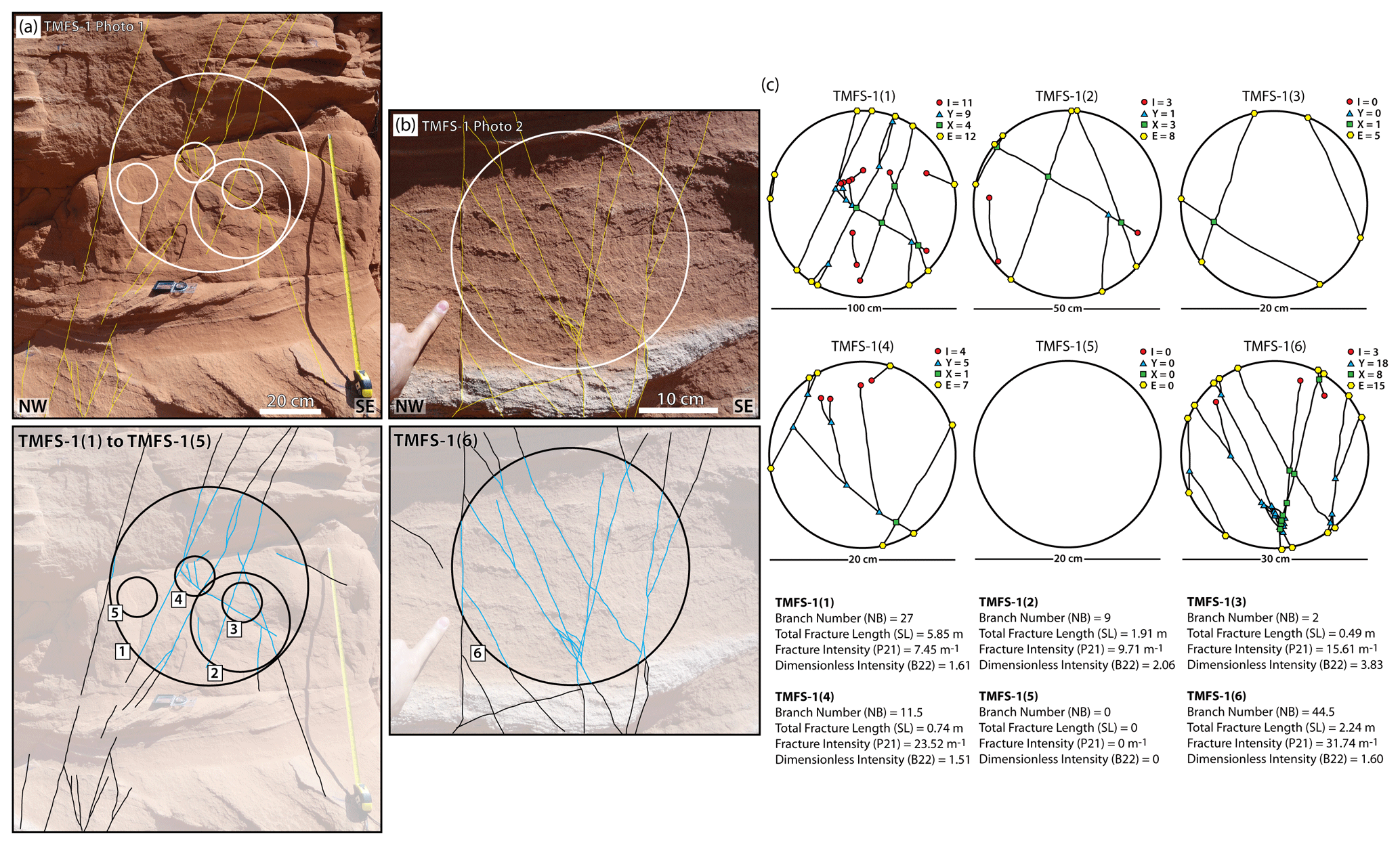

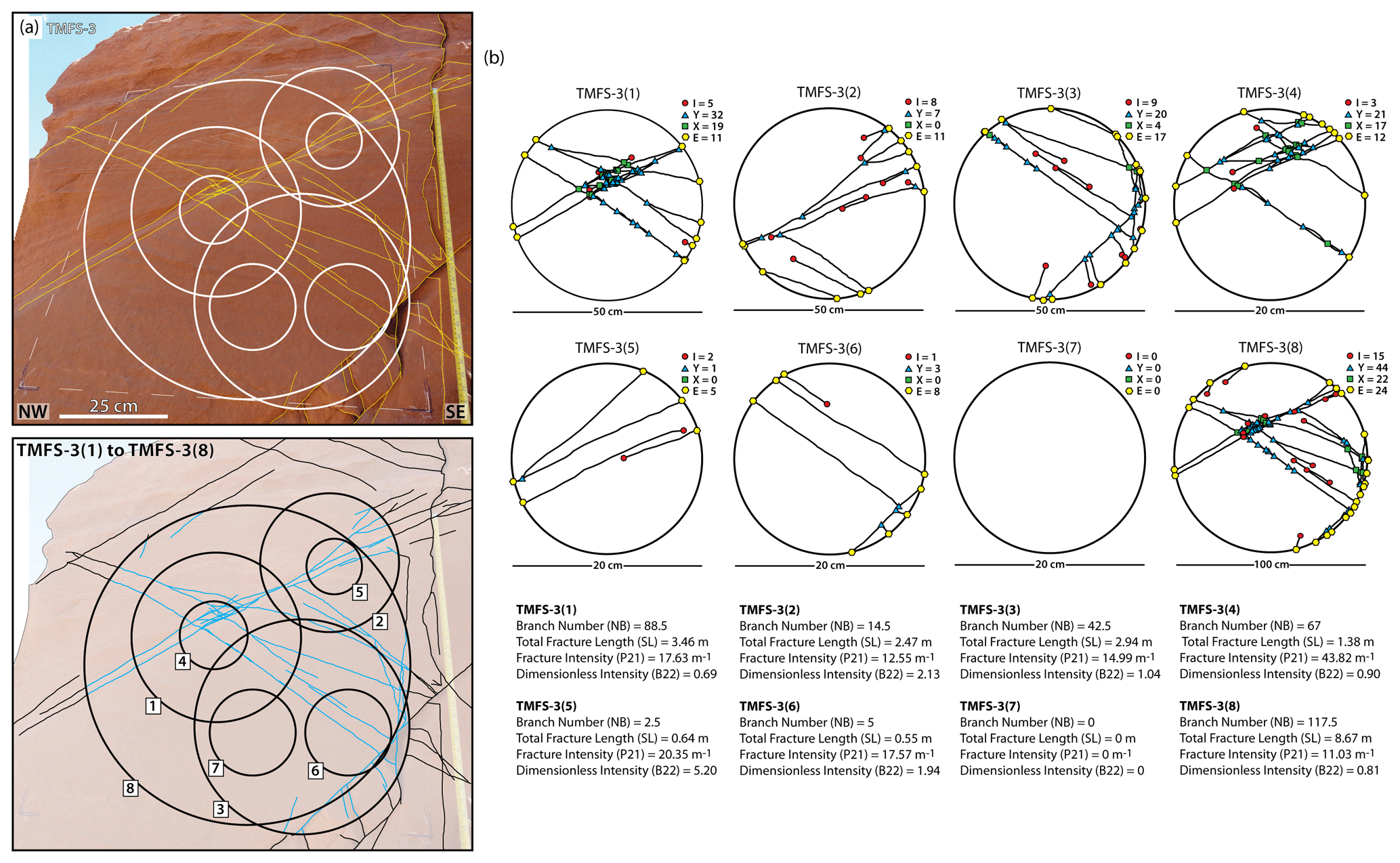

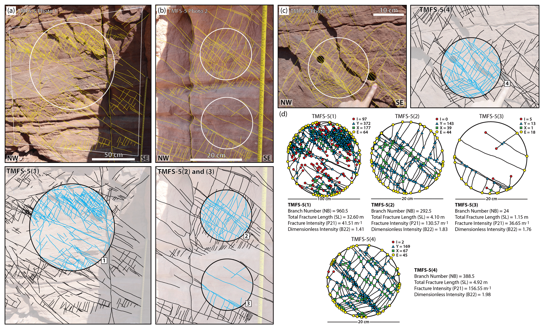
Figure A5Sample station TMFS-5 scan circles (a, b, c) and nodal analysis (d) with statistics.
The data set used in this paper can be found in the Supplement.
The supplement related to this article is available online at: https://doi.org/10.5194/se-12-95-2021-supplement.
PIRW designed and conducted the research, interpreted the data and prepared the manuscript. RWW designed the study and assisted with data analysis and manuscript preparation. DJS assisted with data analysis and manuscript preparation. IJ assisted with data analysis and manuscript preparation. KJWM assisted with manuscript preparation.
The authors declare that they have no conflict of interest.
This article is part of the special issue “Faults, fractures, and fluid flow in the shallow crust”. It is not associated with a conference.
The authors would like to thank from Laurel Goodwin, Craig Magee, Peter Eichhubl and an anonymous reviewer for their constructive reviews and editorial feedback which have helped enhance the manuscript. The authors would also like to thank Casey Nixon for advice during the development of the work. Penelope I. R. Wilson acknowledges Kingston University London for PhD funding and laboratory access that supported this research. David J. Sanderson acknowledges support from a Leverhulme Emeritus fellowship during the development of this work.
This paper was edited by Peter Eichhubl and reviewed by Laurel Goodwin and one anonymous referee.
Aarnes, I., Planke, S., Trulsvik, M., and Svensen, H.: Contact metamorphism and thermogenic gas generation in the Vøring and Møre basins, offshore Norway, during the Paleocene–Eocene thermal maximum, J. Geol. Soc. Lond., 172, 588–598, https://doi.org/10.1144/jgs2014-098, 2015.
Adler, P. M. and Thovret, J. F.: Fractures and fractures networks (theory and applications of transport in porous media), Springer, Dordrecht, https://doi.org/10.1007/978-94-017-1599-7, 431 pp., 1999.
Ameen, M. S.: Macrofaulting in the Purbeck–Isle of Wight monocline, Proc. Geol. Assoc., 101, 31–46, https://doi.org/10.1016/S0016-7878(08)80204-0, 1990.
Antonellini, M. and Aydin, A.: Effect of faulting on fluid flow in porous sandstones: petrophysical properties, AAPG Bull., 78, 355–377, https://doi.org/10.1306/BDFF90AA-1718-11D7-8645000102C1865D, 1994.
Antonellini, M. and Aydin, A.: Effect of faulting on fluid flow in porous sandstones: geometry and spatial distribution, AAPG Bull., 79, 642–670, https://doi.org/10.1306/8D2B1B60-171E-11D7-8645000102C1865D, 1995.
Aydin, A.: Small faults formed as deformation bands in sandstone, Pure Appl. Geophys., 116, 913–930, https://doi.org/10.1007/BF00876546, 1978.
Aydin, A. and Johnson, A. M.: Development of faults as zones of deformation bands and as slip surfaces in sandstone, Pure Appl. Geophys., 116, 931–942, https://doi.org/10.1007/BF00876547, 1978.
Aydin, A. and Johnson, A. M.: Analysis of faulting in porous sandstones, J. Struct. Geol., 5, 19–31, https://doi.org/10.1016/0191-8141(83)90004-4, 1983.
Aydin, A., Borja, R. I., and Eichhubl, P.: Geological and mathematical framework for failure modes in granular rock, J. Struct. Geol., 28, 83–98, https://doi.org/10.1016/j.jsg.2005.07.008, 2006.
Bacelle, L. and Bosellini, A.: Diagrammi per la stima visive della composizionze percentuale nelle rocce sedimentary, Annal. Univ. Ferrara, ser. IX, 1/3, 59–62, 1965.
Ballas, G., Fossen, H., and Soliva, R.: Factors controlling permeability of cataclastic deformation bands and faults in porous sandstone reservoirs, J. Struct. Geol., 76, 1–21, https://doi.org/10.1016/j.jsg.2015.03.013, 2015.
Berkowitz, B.: Analysis of fracture network connectivity using percolation theory, Math. Geol., 27, 467–483, https://doi.org/10.1007/BF02084422, 1995.
Bertelsen, H. S., Rogers, B., Galland, O., and Dumazer, G.: Laboratory modeling of coeval brittle and ductile deformation during magma emplacement into viscoelastic rocks, Front. Earth Sci., 6, 199, https://doi.org/10.3389/feart.2018.00199, 2018.
Brooks Hanson, R.: The hydrodynamics of contact metamorphism, GSA Bull., 107, 595–611, https://doi.org/10.1130/0016-7606(1995)107<0595:THOCM>2.3.CO;2, 1995.
Civan, F.: Fractal formulation of the porosity and permeability relationship resulting in a power-law flow units equation – A leaky-tube model, SEPE International Symposium and Exhibition on Formation Damage Control, Louisiana, https://doi.org/10.2118/73785-MS, 2002.
Civan, F.: Reservoir Formation Damage, 3rd Edn., Gulf Professional Publishing, Oxford, 1042 pp., https://doi.org/10.1016/C2014-0-01087-8, 2015.
Corry, C. E.: Laccoliths: mechanics of emplacement and growth, Geological Society of America Special Papers, 220, 110 pp., 1988.
Cosgrove, J. W.: The association of folds and fractures and the link between folding, fracturing and fluid flow during the evolution of a fold – thrust belt: a brief review, in: Industrial Structural Geology: Principles, edited by: Richards, F. L., Richardson, N. J., Rippington, S. J., Wilson, R. W., and Bond, C. E., Techniques and Integration, Geol. Soc. Lond. Spec. Publ., 421, 41–68, https://doi.org/10.1144/SP421.11, 2015.
Du Bernard, X., Eichhubl, P., and Aydin, A.: Dilation bands: A new form of localized failure in granular media, Geophys. Res. Lett., 29, 2176, https://doi.org/10.1029/2002GL015966, 2002.
Farrell, N. J. C., Healy, D., and Taylor C. W.: Anisotropy of permeability in faulted porous sandstones, J. Struct. Geol., 63, 50–67, https://doi.org/10.1016/j.jsg.2014.02.008, 2014.
Eichhubl, P., Hooker, J., and Laubach, S. E.: Pure and shear-enhanced compaction bands in Aztec Sandstone, J. Struct. Geol., 32, 1873–1886, https://doi.org/10.1016/j.jsg.2010.02.004, 2010.
Fossen, H.: Structural Geology, Cambridge University Press, Cambridge, 463 pp., 2010.
Fossen, H. and Bale, A.: Deformation bands and their influence on fluid flow, AAPG Bull., 91, 1685–1700, https://doi.org/10.1306/07300706146, 2007.
Fossen, H., Schultz, R. A., Shipton, Z. K., and Mair, K.: Deformation bands in sandstone: a review, J. Geol. Soc. Lond., 164, 755–769, https://doi.org/10.1144/0016-76492006-036, 2007.
Galland, O., Schmiedel, T., Bertelsen, H., Guldstrand, F., Haug, Ø., and Souche, A.: Geomechanical modelling of fracturing and damage induced by igneous intrusions: implications for fluid flow in volcanic basins, 10 Congreso de Exploración y Desarrollo de Hidrocarburos – Simposio de Geomecánica: Eficiencia a innovación a través de la geomecánica el la exploración y desarrollo de reservorios, 101–120, 2018.
Garden, I. R., Guscott, S. C., Burley, S. D., Foxford, K. A., Walsh, J. J., and Marshall, J.: An exhumed palaeo-hydrocarbon migration fairway in a faulted carrier system, Entrada Sandstone of SE Utah, USA, Geofluids, 1, 195–213, https://doi.org/10.1046/j.1468-8123.2001.00018.x, 2001.
Gardiner, D., Schofield, N., Finlay, A., Mark, N., Holt, L., Grove, C., Forster, C., and Moore, J.: Modelling petroleum expulsion in sedimentary basins: The importance of igneous intrusion timing and basement composition, Geology, 47, 10, 904–908, https://doi.org/10.1130/G46578.1, 2019.
Gibson, R. G.: Physical character and fluid-flow properties of sandstone-derived fault zones, Geol. Soc. Lond. Spec. Publ., 127, 83–97, https://doi.org/10.1144/GSL.SP.1998.127.01.07, 1998.
Hansen, D. M. and Cartwright, J.: The three-dimensional geometry and growth of forced folds above saucer-shaped igneous sills, J. Struct. Geol., 28, 1520–1535, https://doi.org/10.1016/j.jsg.2006.04.004, 2006.
Heilbronner, R. and Barrett, S.: Volume Determinations, in: Image Analysis in Earth Sciences, Springer, Berlin, Heidelberg, 173–185, https://doi.org/10.1007/978-3-642-10343-8_10, 2014.
Hintze, L. E. and Kowallis, B. J.: A field guide to Utah's Rock: Geological History of Utah, Brigham Young Univ. Geol. Stud. Spec. Publ., 9, 225 pp., 2009.
Holford, S. P., Schofield, N., Macdonald, J. D., Duddy, I. R., and Green, P. F.: Seismic analysis of igneous systems in sedimentary basins and their impacts on hydrocarbon prospectivity: examples from the southern Australian margin, APPEA J., 52, 229–252, https://doi.org/10.1071/AJ11017, 2012.
Hunt, C. B.: Geology and geography of the Henry Mountains region, Utah: A survey and restudy of one of the classic areas in geology, Vol. 228, US Government Printing Office, 1953.
Irvine, T. N.: Heat transfer during solidification of layered intrusions. I. Sheets and sills, Can. J. Earth Sci., 7, 1031–1061, https://doi.org/10.1139/e70-098, 1970.
Jackson, S. E. and Pollard, D. D.: The laccolith-stock controversy: New results from the southern Henry Mountains, Utah, GSA Bull., 100, 117–139, https://doi.org/10.1130/0016-7606(1988)100%3C0117:TLSCNR%3E2.3.CO;2, 1988.
Jaeger, J. C.: Thermal effects of intrusions, Rev. Geophys., 2, 443–466, https://doi.org/10.1029/RG002i003p00443, 1964.
Johnson, A. M. and Pollard, D. D.: Mechanics of growth of some laccolithic intrusion in the Henry Mountains, Utah, I: Field observations, Gilbert's model, physical properties and flow of the magma, Tectonophys, 18, 261–309, https://doi.org/10.1016/0040-1951(73)90050-4, 1973.
Kampman, N., Maskell, A., Bickle, M. J., Evans, J. P., Schaller, M., Purser, G., Zhou, Z., Gattacceca, J., Peitre, E. S., Rochelle, C. A., Ballentine, C. J., Busch, A., and Scientists of the GRDP: Scientific drilling and downhole fluid sampling of a natural CO2 reservoir, Green River, Utah, Sci. Dril., 16, 33–43, https://doi.org/10.5194/sd-16-33-2013, 2013.
Kavanagh, J. L., Menand, T., and Sparks, R. S. J.: An experimental investigation of sill formation and propagation in layered elastic media, Earth Planet. Sc. Lett., 245, 799–813, https://doi.org/10.1016/j.epsl.2006.03.025, 2006.
Knipe, R. J., Fisher, Q. J., and Clennell, M. R.: Fault seal analysis: successful methodologies, application and future directions, in: Hydrocarbon Seals: Importance for Exploration and Production, edited by: Møller-Pedersen, P. and Koestler, A. G., Norwegian Petrol. Soc. Spec. Pub., 7, 15–40, https://doi.org/10.1016/S0928-8937(97)80004-5, 1997.
Mäkel, G. H.: The modelling of fractured reservoirs: constraints and potential for fracture network geometry and hydraulics analysis, Geol. Soc. Lond. Spec. Publ., 292, 375–403, https://doi.org/10.1144/SP292.21, 2007.
Malthe-Sørrenssen, A., Planke, S., Svensen, H., and Jamtveit, B.: Formation of saucer-shaped sills, in: Physical Geology of High-level Magmatic Systems, edited by: Breitkreuz, C. and Petford, N., Geol. Soc. Lond., Spec. Pub., 324, 215–227, https://doi.org/10.1144/GSL.SP.2004.234.01.13, 2004.
Manzocchi, T.: The connectivity of two dimensional networks of spatially correlated fractures, Water Resour. Res., 38, 1162, https://doi.org/10.1029/2000WR000180, 2002.
Mark, N., Holford, S., Schofield, N., Eide, C. H., Pugliese, S., Watson, D., and Muirhead, D.: Structural and lithological controls on the architecture of igneous intrusions: examples from the NW Australian Shelf, Petrol. Geosci., 26, 50–69, https://doi.org/10.1144/petgeo2018-067, 2020.
Mauldon, M., Dunne, W. M., and Rohrbaugh, M. B.: Circular scanlines and circular windows: new tools for characterizing the geometry of fracture traces, J. Struct. Geol., 23, 247–258, https://doi.org/10.1016/S0191-8141(00)00094-8, 2001.
Menand, T.: The mechanics and dynamics of sills in layered elastic rocks and their implications for growth of laccoliths and other igneous complexes, Earth Planet. Sc. Lett., 267, 93–99, https://doi.org/10.1016/j.epsl.2007.11.043, 2008.
Montanari, D., Bonini, M., Corti, G., Agostini, A., and Ventisette, C. D.: Forced folding above shallow magma intrusions: Insights on supercritical fluid flow from analogue modelling, J. Volcanol. Geoth. Res., 345, 67–80, https://doi.org/10.1016/j.jvolgeores.2017.07.022, 2017.
Morgan, S., Stanik, A., Horsman, E., Tikoff, B., de Saint Blanquat, M., and Habert, G.: Emplacement of multiple magma sheets and wall rock deformation: Trachyte Mesa intrusion, Henry Mountains, Utah, J. Struct. Geol., 30, 491–512, https://doi.org/10.1016/j.jsg.2008.01.005, 2008.
Nelson, S. T., Davidson, J. P., and Sullivan, K. R.: New age determinations of central Colorado Plateau laccoliths, Utah: Recognizing disturbed K–Ar systematics and re-evaluating tectonomagmatic relationships, GSA Bull., 104, 1547–1560, https://doi.org/10.1130/0016-7606(1992)104<1547:NADOCC>2.3.CO;2, 1992.
Ogilvie, S. R. and Glover, P. W. J.: The petrophysical properties of deformation bands in relation to their microstructure, Earth Planet. Sc. Lett., 193, 129–142, https://doi.org/10.1016/S0012-821X(01)00492-7, 2001.
Ogilvie, S. R., Orribo, J. M., and Glover, P. W. J.: The influence of deformation bands upon fluid flow using profile permeametry and positron emission tomography, Geophys. Res. Lett., 38, 61–64, https://doi.org/10.1029/2000GL008507, 2001.
Parnell, J., Watt, G. R., Middleton, D., Kelly, J., and Barton, M.: Deformation band control on hydrocarbon migration, J. Sediment. Res., 74, 552–560, https://doi.org/10.1306/121703740552, 2004.
Peacock, D. C. P., Nixon, C. W., Rotevatn, A., Sanderson, D. J., and Zuluaga, L. F.: Glossary of fault and fracture networks, J. Struct. Geol., 92, 12–29, https://doi.org/10.1016/j.jsg.2016.09.008, 2016.
Pettijohn, F. J., Potter, P. E., and Siever, R.: Sand and Sandstone, 2nd Edn., Springer, Berlin Heidelberg New York, 553 pp., 1987.
Pollard, D. D. and Johnson, A. M.: Mechanics of growth of some laccolithic intrusions in the Henry Mountains, Utah, II. Bending and failure of overburden layers and sill formation, Tectonophysics, 18, 311–354, https://doi.org/10.1016/0040-1951(73)90051-6, 1973.
Priest, S. D.: Discontinuity analysis for rock engineering, Chapman and Hall, London, 473 pp., https://doi.org/10.1007/978-94-011-1498-1, 1993.
Procter, A. and Sanderson, D. J.: Spatial and layer-controlled variability in fracture networks, J. Struct. Geol., 108, 52–65, https://doi.org/10.1016/j.jsg.2017.07.008, 2018.
Rateau, R., Schofield, N., and Smith, M.: The potential role of igneous intrusions on hydrocarbon migration, West of Shetland, Petrol. Geosci., 19, 259–272, https://doi.org/10.1144/petgeo2012-035, 2013.
Riley, M. S.: Fracture trace length and number distributions from fracture mapping, J. Geophys. Res., 110, B08414, https://doi.org/10.1029/2004JB003164, 2005.
Rodriguez-Monreal, F., Villar, H. J., Baudino, R., Delpino, D., and Zencichi, S.: Modeling an atypical petroleum system: A case study of hydrocarbon generation, migration and accumulation related to igneous intrusions in the Neuquen Basin, Argentina, Mar. Petrol. Geol., 26, 590–605, https://doi.org/10.1016/j.marpetgeo.2009.01.005, 2009.
Rohrbaugh, M. B., Dunne, W. M., and Mauldon, M.: Estimating fracture trace intensity, density, and mean length using circular scan lines and windows, AAPG Bull., 86, 2087–2102, https://doi.org/10.1306/61EEDE0E-173E-11D7-8645000102C1865D, 2002.
Rossetti, F., Tecce, F., and Billi, A.: Patterns of fluid flow in the contact aureole of the Late Miocene Monte Capanne pluton (Elba Island, Italy): the role of structures and rheology, Contrib. Mineral. Petrol., 153, 743–760, https://doi.org/10.1007/s00410-006-0175-3, 2007.
Rotevatn, A., Sandve, T. H., Keilegavlen, E., Kolyukhin, D., and Fossen, H.: Deformation bands and their impact on fluid flow in sandstone reservoirs: the role of natural thickness variations, Geofluids, 13, 359–371, https://doi.org/10.1111/gfl.12030, 2013.
Saillet, E. and Wibberley, C. A. J.: Permeability and flow impact of faults and deformation bands in high-porosity sand reservoirs: Southeast Basin, France, analog, AAPG Bull., 97, 437–464, https://doi.org/10.1306/09071211191, 2013.
Sanderson, D. J. and Nixon, C. W.: The use of topology in fracture network characterization, J. Struct. Geol., 72, 55–66, https://doi.org/10.1016/j.jsg.2015.01.005, 2015.
Sanderson, D. J. and Nixon, C. W.: Topology, connectivity and percolation in fracture networks, J. Struct. Geol., 115, 167–177, https://doi.org/10.1016/j.jsg.2018.07.011, 2018.
Schneider, C., Rasband, W., and Eliceiri, K.: NIH Image to ImageJ: 25 years of image analysis, Nat Methods, 9, 671–675, https://doi.org/10.1038/nmeth.2089, 2012.
Schultz, R. A., Okubo, C. H., and Fossen, H.: Porosity and grain size controls on compaction band formation in Jurassic Navajo Sandstone, Geophys. Res. Lett., 37, L22306, https://doi.org/10.1029/2010GL044909, 2010.
Scott, S., Driesner, T., and Weis, P.: Geologic controls on supercritical geothermal resources above magmatic intrusions, Nat. Commun., 6, 7837, https://doi.org/10.1038/ncomms8837, 2015.
Senger, K., Planke, S., Polteau, S., Ogata, K., and Svensen, H.: Sill emplacement and contact metamorphism in a siliciclastic reservoir on Svalbard, Arctic Norway. Norwegian J. Geol., 94, 155–169, 2014.
Senger, K., Buckley, S. J., Chevallier, L., Fagereng, Å., Galland, O., Kurz, T. H., Ogata, K., Planke, S., and Tveranger, J.: Fracturing of doleritic intrusions and associated contact zones: implications for fluid flow in volcanic basins, J. Afr. Earth Sci., 102, 70–85, https://doi.org/10.1016/j.jafrearsci.2014.10.019, 2015.
Shipton, Z. K. and Cowie, P. A.: Damage zone and slip-surface evolution over µm to km scales in high-porosity Navajo sandstone, Utah, J. Struct. Geol., 23, 1825–1844, https://doi.org/10.1016/S0191-8141(01)00035-9, 2001.
Sigda, J. M., Goodwin, L. B., Mozley, P. S., and Wilson, J. L.: Permeability alteration in small-displacement faults in poorly lithified sediments: Rio Grande rift, central New Mexico, in: Faults and Subsurface Fluid Flow in the Shallow Crust, edited by: Haneberg, W. C., Mozley, P. S., Moore, J. C., and Goodwin, L. B., AGU Monograph 113, 51–68, https://doi.org/10.1029/GM113p0051, 1999.
Skurtveit, E., Torabi, A., Alikarami, R., and Braathen, A.: Fault baffle to conduit developments: reactivation and calcite cementation of deformation band fault in aeolian sandstone, Petrol. Geosci., 2, 3–16, https://doi.org/10.1144/petgeo2014-031, 2015.
Soliva, R., Schultz, R. A., Ballas, G., Taboada, A., Wibberley, C. A. J., Saillet, E., and Benedicto, A.: A model of strain localization in porous sandstone as a function of tectonic setting, burial and material properties; new insight from Provence (SE France), J. Struct. Geol., 49, 50–63, https://doi.org/10.1016/j.jsg.2012.11.011, 2013.
Sternlof, K. R., Chapin, J. R., Pollard, D. D., and Durlofsky, L. J.: Permeability effects of deformation band arrays in sandstone, AAPG Bull., 88, 1315–1329, 2004.
Sternlof, K., Karimi-Fard, M., Pollard, D. D., and Durlofsky, L. J.; Flow and transport effects of compaction bands in sandstone at scales relevant to aquifer and reservoir management, Water Resour. Res., 42, W07425, https://doi.org/10.1029/2005WR004664, 2006.
Sun, W., Andrade, J. E., Rudnicki, J. W., and Eichhubl, P.; Connecting microstructural attributes and permeability from 3D tomographic images of in situ shear-enhanced compaction bands using multiscale computations, Geophys. Res. Lett., 38, L10302, https://doi.org/10.1029/2011GL047683, 2011.
Taylor, W. L. and Pollard, D. D.: Estimation of in situ permeability of deformation bands in porous sandstone, Valley of Fire, Nevada, Water Resour. Res., 3, 2595–2606, https://doi.org/10.1029/2000WR900120, 2000.
Torabi, A., Fossen, H., and Alaei, B.: Application of spatial correlation functions in permeability estimation of deformation bands in porous rocks, J. Geophys. Res., 113, B08208, https://doi.org/10.1029/2007JB005455, 2008.
Tucker, M. E.: Sedimentary Petrology. An Introduction to the Origin of Sedimentary Rocks, 3rd Edn., Blackwell Science, Oxford, 262 pp., 2001.
Tueckmantel, C., Fisher, Q. J., Manzocchi, T., Skachkov, S., and Grattoni, C. A.: Two-phase fluid flow properties of cataclastic fault rocks: implication for CO2 storage in saline aquifers, Geology, 20, 39–42, https://doi.org/10.1130/G32508.1, 2012.
Underhill, J. R. and Woodcock, N. H.: Faulting mechanisms in high-porosity sandstones; New Red Sandstone, Arran, Scotland, in: Deformation of Sediments and Sedimentary Rocks, edited by: Jones, M. E. and Preston, R. M. F., Geol. Soc. Lond. Spec. Pub. 29, 91–105, https://doi.org/10.1144/GSL.SP.1987.029.01.09, 1987.
Walsh, J. J. and Watterson, J.: Fractal analysis of fracture patterns using the standard box-counting technique: valid and invalid methodologies, J. Struct. Geol., 15, 1509–1512, https://doi.org/10.1016/0191-8141(93)90010-8, 1993.
Weis, P.: The dynamic interplay between saline fluid flow and rock permeability in magmatic-hydrothermal systems, Geofluids, 15, 350–371, https://doi.org/10.1111/gfl.12100, 2015.
Westerman, D., Rocchi, S., Breitkreuz, C., Stevenson, C., and Wilson, P. I. R.: Structures related to the emplacement of shallow-level intrusions: Dykes, sills and laccoliths, in: Physical Geology of Shallow Magmatic Systems, edited by: Breitkreuz, C. and Rocchi, S., Advances in Volcanology, Springer, Cham, 83–118, https://doi.org/10.1007/978-3-319-14084-1_31, 2017.
Wetmore, P. H., Connor, C. B., Kruse, S. E., Callihan, S., Pignotta, G., Stremtan, C., and Burke, A.: Geometry of the Trachyte Mesa intrusion, Henry Mountains, Utah: Implications for the emplacement of small melt volumes into the upper crust, Geochem. Geophy. Geosy., 10, Q08006, https://doi.org/10.1029/2009GC002469, 2009.
Wibberley, C. A. J., Petit, J.-P., and Rives T.: The mechanics of fault distribution and localization in high-porosity sands, Provence, France, in: The Relationship between Damage and Localization, edited by: Lewis, H. and Couples, G. D., Geol. Soc. Lond. Spec. Publ., 164, 599–608, https://doi.org/10.1144/SP289.3, 2007.
Wilson, P. I. R., McCaffrey, K. J. W., Wilson, R. W., Jarvis, I., and Holdsworth, R. E.: Deformation structures associated with the Trachyte Mesa intrusion, Henry Mountains, Utah: Implications for sill and laccolith emplacement mechanisms, J. Struct. Geol., 87, 30–46, https://doi.org/10.1016/j.jsg.2016.04.001, 2016.
Wilson, P. I. R., McCaffrey, K. J. W., and Holdsworth, R. E.: Magma-driven accommodation structures formed during sill emplacement at shallow crustal depths: The Maiden Creek sill, Henry Mountains, Utah, Geosphere, 15, 1368–1392, https://doi.org/10.1130/GES02067.1, 2019.