the Creative Commons Attribution 4.0 License.
the Creative Commons Attribution 4.0 License.
 | 30 May 2023
Structural control of inherited salt structures during inversion of a domino basement-fault system from an analogue modelling approach
Eloi Carola
Ken McClay
The geometries of inverted rift systems are different depending on a large variety of factors that include, among others, the presence of decoupling layers, the thickness of the pre- and syn-extension successions, or structural inheritances. Our study focuses on the inversion of an extensional domino-style basement-fault system with a pre-extension salt layer using analogue models to understand the role of pre-existing structural features during inversion. Models investigate how different overburden and salt thicknesses, inherited extensional structures, and salt distributions condition the evolution during inversion. The experimental results show that models with thick salt can partially or totally preserve the extensional ramp–syncline basin geometry independently of the overburden thickness. In contrast, models with a thin salt layer result in a total inversion of the ramp–syncline basins with the development of crestal collapse grabens and extensional faults affecting the overburden. Inversion also triggered the growth or reactivation of salt-related structures such as primary weld reopening and/or obliteration, diapir rejuvenation, salt thickening, or thrust emplacement. The use of analogue modelling allowed us to address the processes that controlled the growth and evolution of these structural elements during the inversion. Experimental results also provide a template of different structural styles resulting from the positive inversion of basins with a pre-extensional salt layer that can help subsurface interpretation in areas with poor seismic imaging.
- Article
(16969 KB) - Full-text XML
- BibTeX
- EndNote


Basin inversion is conditioned by the inherited structural grain and the stratigraphic elements but also by the tectono-sedimentary evolution through time (Nemčok et al., 1995; Turner and Williams, 2004; Panien et al., 2005; Bonini et al., 2012; Lacombe and Bellahsen, 2016). In inverted rift systems, it is common to find broad anticlines in the hanging wall of major basement faults made up of either post-extension or syn-inversion rocks that in turn are cored by thickened syn-extensional successions (Fig. 1) (e.g. Badley et al., 1989; Gowers et al., 1993; Bonini et al., 2012; Jagger and McClay, 2018; Hansen et al., 2021). Inversion also entails a shift in the depocentre locations, with the extensional ones located close to the major basement fault (Fig. 1a) and those related to the inversion flanking the newly formed structural relief made by the uplifted basin (Fig. 1b–d) (Bally, 1984). If rift basins include salt layers, the degree of linkage between the overburden and the basement highly constrains the extensional evolution but also their subsequent inversion (Stewart and Clark, 1999; Jackson et al., 2013; Rowan and Krzywiec, 2014). The ratio between salt and overburden thicknesses (Withjack and Callaway, 2000; Withjack et al., 2002; Ferrer et al., 2023) as well as the location of salt and extensional structures developed under extension (Koyi et al., 1993; Dooley et al., 2005; Duffy et al., 2013; Ferrer et al., 2016; Roma et al., 2018a; Granado et al., 2021) constrain the structural style during subsequent inversion (i.e. diapir squeezing, reactivation of inherited extensional faults, development of new thrust, degree of coupling or decoupling). In salt-bearing rift basins, salt acts as a contractional detachment, with diapirs and salt walls as the weakest structures of the basin infill and where deformation is going to be concentrated during early inversion (Costa and Vendeville, 2002; Brun and Fort, 2004; Callot et al., 2007; Dooley et al., 2014; Dooley and Hudec, 2020). Shortening rejuvenates salt structures buried at the end of the extension and the overburden can be pierced by diapirs, even with a thick overburden (Bonini et al., 2012; Roma et al., 2018b; Dooley and Hudec, 2020). At this stage, salt can extrude, forming sheets (Jackson and Hudec, 2017). As shortening progresses, diapirs are squeezed, developing secondary welds, thrust welds, or decapitated diapirs (Dooley et al., 2014; Roma et al., 2018b; Vidal-Royo et al., 2021; Rowan et al., 2022).
Figure 1Schematic example of basin inversion of a domino-style basement fault lacking a decoupling layer. (a) Structural configuration at the end of the extensional episode; (b) early stage of inversion with the reactivation of the basement fault producing an incipient basin uplift; (c) mild inversion stage and development of shortcuts affecting the whole sedimentary succession; (d) final configuration when total inversion is reached. Note the different distributions of the syn-kinematic depocentres (i.e. extension and inversion successions). Redrawn from an analogue model by Jagger and McClay (2018).
Analogue modelling investigating the inversion of former extensional basins with isotropic infills has been widely addressed in the literature (i.e. Buchanan and McClay, 1992; Letouzey et al., 1995; Yamada and McClay, 2003; Jagger and McClay, 2018), but the number of works on inverted basins with mechanical anisotropies in the sedimentary fill caused by salt layers is scarce (for a detailed review, see Bonini et al., 2012). While some of these studies considered pre-rift salt (i.e. Brun and Nalpas, 1996; Withjack and Callaway, 2000; Dooley et al., 2005; Burliga et al., 2012; Ferrer et al., 2016, 2023), others investigate the role of syn-rift salt during inversion (i.e. Del Ventisette et al., 2005; Roma et al., 2018a; Dooley and Hudec, 2020). Regardless of when salt was deposited (pre- or syn-extension), most of these works used non-rotational rigid blocks with different geometries and configurations to constrain the geometry of basement faults. Dooley and Hudec (2020) used an original setup based on polymer seeds to constrain the geometry of segmented rifts subsequently inverted. The resulting basins were filled with syn-rift salt, and they analysed the styles of shortening in the sub- and supra-salt section.
The present work complements and expands upon the experimental programme presented by Ferrer et al. (2023), in which from a systematic set of 2D analogue models simulating an extensional domino-style basement-fault system and a pre-rift salt, different parameters controlling the architecture and kinematic of salt-bearing rift basins are studied (i.e. the interplay between pre-rift salt and overburden thicknesses, the syn-kinematic sedimentation rate, and the development and evolution of primary welds). Taking advantage of the extensional templates in the experiments with a single pre-kinematic salt layer from Ferrer et al. (2023), the present work focuses on the positive inversion of those models. In this new experimental programme, two parameters (salt and pre-extensional overburden thicknesses) have been systematically tested to understand how inherited salt-related structures preferentially localize contractional deformation in a domino basement-fault system during inversion and also how reactivation of primary extensional welds occurs. The set of extension–inversion models presented in this work is intended to answer several key questions when working in inversion tectonic settings with a pre-rift decoupling layer. Among others, these include understanding how salt-related structures are affected during shortening and how salt migrates during this stage. Linked with salt migration, comprehending the behaviour of primary salt welds and how they evolve is of importance in interpreting the evolution of structures through time as well as the final geometry of the inverted basin.
2.1 Experimental programme, setup, and procedure
The experimental programme was carried out in a rig consisting of five fault blocks simulating a domino fault system (Fig. 2a). The 70 cm long by 25 cm wide deformation rig is made up of five metal blocks whose geometry simulates four basement faults (F1 to F4 in Fig. 2a). Four blocks were able to rotate while one was kept fixed at the end of the rig. Each rotational block was attached to a basal trellis system that transmitted the motions (Fig. 2a). Extension and compression were applied by an electric motor worm screw at a velocity rate of 4.6 mm h−1. The sandbox was encased by two lateral glass walls that enabled recording the kinematic evolution of the experiments (Fig. 2a). It should be noted that the design of the rig makes the fault displacement greater in F4, progressively decreasing towards F1. In this way, for a specific experimental configuration, this allows the comparison of equivalent structures with different evolutionary stages for both extension and inversion at each basement block (Fig. 2). For more details, we refer the reader to Jagger and McClay (2018) and Ferrer et al. (2023) wherein the experimental apparatus is explained in detail.
Figure 2Sketch of the deformation rig used to simulate extension of a domino-style basement-fault system. (a) Pre-extensional configuration and sedimentary infill characterized by a bluish layered sand pack with an intervening polymer covering the entire model. (b) Configuration at the end of extension characterized by a reddish syn-kinematic sand pack deposited as basement faults increase displacement. (c) End of the compression configuration reaching total inversion.
The pre-extensional unit distribution was characterized by a flat basement overlain by a 30 mm thick pre-kinematic unit of alternating layers of blue, white, and black quartz sand that were levelled with a scraper (e.g. Krantz, 1991; Lohrmann et al., 2003). Transparent polymer (either 5 or 10 mm thick depending on the model, see Table 1) was deposited on top of the quartz sand. The final pre-kinematic cover sand was sieved on top of the polymer and consisted of alternating 2.5 mm thick blue, white, and black sand layers flattened with the scraper up to a total thickness of 7.5 or 15 mm depending on the model (Fig. 2a and Table 1).
Table 1Summary table with the main characteristics of the experimental programme included in this article.
The four extensional experiments (DOM4, DOM5, DOM6, and DOM8) by Ferrer et al. (2023) were repeated with the same parameters and were subsequently inverted (DOM9, DOM12, DOM19, and DOM21, respectively). As a result, the experimental programme presented in this work consists of four pairs of extension–inversion models that can be directly compared (Table 1).
At the beginning of the extension, the dip of the four faults limiting the metal blocks was 60∘ towards the moving wall. As the extension increased, the counterclockwise rotation of the blocks caused the decrease in dip of the fault plane (faults F2, F3, and F4), reaching 50∘ at the end of the extension phase (Fig. 2b). The dip of F1, limited by the static footwall block, remained the same throughout the experiment (Fig. 2b). All models underwent 10 cm of total extension (Table 2), and syn-kinematic sedimentation was added systematically every 5 mm of extension keeping the pre-extensional regional datum constant (top of the pre-kinematic unit above the static block). The newly developed basins were filled by alternating red, white, and black syn-kinematic sand layers; the positive reliefs caused by salt inflation were episodically eroded with the scraper and the sand was vacuumed (Fig. 2b). The extensional procedure was systematically repeated for models DOM9, DOM12, DOM19, and DOM21, but they were subsequently shortened 10 cm to reach total inversion (Fig. 2c and Table 1). During this stage, no syn-kinematic sedimentation or erosion was applied, and therefore the top of the model corresponded to the inverted geometry of the extensional basins. This procedure was applied to not distort the inversion of the faults and the contractional reactivation of salt structures by the syn-kinematic sedimentation.
Table 2Scaling parameters used in the experimental programme.
* Thickness at the beginning of the extension.
At the end of the experiments, all the models were covered with sand, preserving the final topography but also preventing polymer flow. Finally, they were preserved with a gelling agent and sliced perpendicular to the trend of the major structures in closely spaced vertical serial sections (3 mm thick) with a slicing machine.
2.2 Mechanical properties of the analogue materials and scaling
Analogue materials consisted of layered, moderately well-rounded coloured and uncoloured dry quartz sand simulating the brittle behaviour of the upper crustal rocks (Davy and Cobbold, 1991; Lohrmann et al., 2003), as well as a silicone polymer (polydimethylsiloxane or PDMS) that deformed in a viscous manner simulating salt in nature (Weijermars, 1986; Weijermars et al., 1993; Couzens-Schultz et al., 2003; Dell'Ertole and Schellart, 2013). The quartz sand, with Mohr–Coulomb rheology (Horsfield, 1977), was sieved to homogenize the grain sizes averaging 65 to 125 µm. To colour it, dyes were used without any appreciable disturbance in the mechanical properties. The sand has a bulk density of 1500 kg m−3, an angle of internal friction between 30 and 35∘, a coefficient of internal friction of 0.59, and a low apparent cohesive strength of 78–142 Pa (Jagger and McClay, 2018). The PDMS polymer used to simulate the salt has a density of 972 kg m−3 and a viscosity of 1.6×10⁴ Pa s when deformed at a laboratory strain rate of cm s−1 at room temperature, thus having nearly perfect Newtonian behaviour (Dell'Ertole and Schellart, 2013). Finally, the methodology by Hubbert (1937), Davy and Cobbold (1988), and Schellart (2000) has been used to dynamically scale the models with natural analogues by a factor of 10−5 (Table 2).
2.3 Data capture, analysis, and visualization techniques
Time-lapse photography, with images taken every 2 min with high-resolution cameras, was used to record the evolution of deformation from both the laterals and from the top of the models. Once the models were finished, they were preserved and closely sliced. The 3 mm thick vertical slices were photographed with high-resolution cameras to create 3D voxels that can be virtually sliced in any direction (see Dooley et al., 2009; Ferrer et al., 2016, 2022, for more details). The workflow proposed by Hammerstein et al. (2014) has been improved in-house by converting the final serial sections into synthetic seismic volumes (Fig. 3), allowing them to be imported into commercial software (Petrel from Schlumberger and PaleoScan from Eliis) (Ferrer et al., 2022). The resultant input data form a 3D SEGY of each model that is then used to perform the interpretation of the different faults and horizons. Since it is then possible for the data to be visualized in 3D, the interpretation is better constrained in all directions, thus reducing the uncertainties (Fig. 3). Once the interpretation is finished, the different horizons and structures can be gridded and trimmed, obtaining a 3D structural model. This workflow allows using all the software capabilities (i.e. visualization, interpretation, and surface modelling) to then obtain well-constrained high-resolution surfaces and minimize interpolation issues and oblique geometries (Fig. 3).
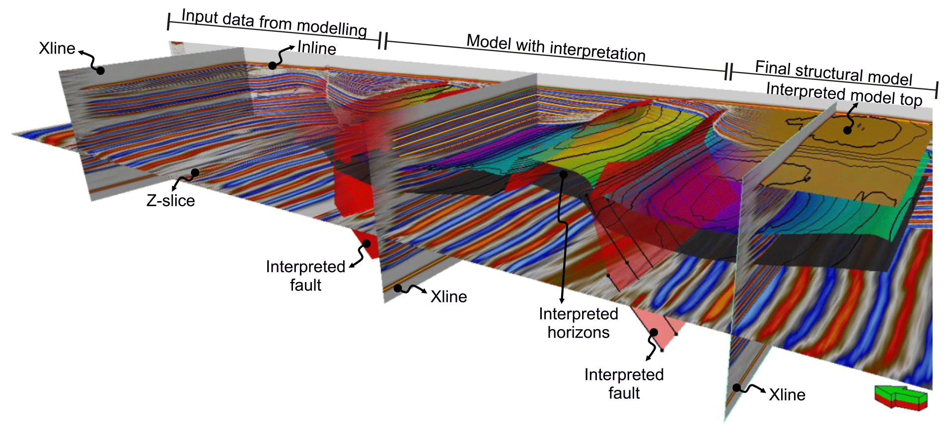
Figure 3Example of a 3D SEGY generated from the vertical slices of the model showing the ability to display or hide the interpretation but also the final 3D structural model generated from the interpretation of the input data.
This section presents the results of the four pairs of extension–inversion models that integrate the systematic experimental programme (Table 1). Models DOM4, DOM5, DOM6, and DOM8 analyse the interplay between the thickness of the pre-extensional polymer layer and the overburden above a planar-rotational basement-fault system, whereas DOM12, DOM19, DOM9, and DOM21 focus on the inversion of these extensional models (Table 1). To make it clearer, this section has been divided into two subsections; the initial one summarizes the results of the extensional models (see Ferrer et al., 2023, for a more detailed description of models DOM4, DOM5, DOM6, and DOM8), and the second subsection reports the evolution of extensional models during subsequent inversion.
3.1 Extensional stage
Model DOM4, with a thin polymer and a thick pre-kinematic overburden, is characterized by the development of drape fold monoclines above the major basement faults during early extension (see structural configuration above F1 in Fig. 4a). As the extension progresses, the monoclines are breached and eroded, and the basinward panel rotates clockwise, attaining a steeply dipping attitude (compare different evolutionary stages from F2 to F4 in Fig. 4a). The salt layer partitions the deformation below and above it, and therefore, salt-detached structures are developed at different structural positions to accommodate extension. Salt migration favours the development of salt-cored anticlines slightly offset with respect to the basement faults at the upper hinge of the monoclines. Welding triggers the development of collapse grabens at the crest of the salt-cored anticlines by thin-skinned extension (F2 in Fig. 4a). With increasing extension, basement faults propagate through the overburden, and the limb of the basinward monocline progressively steepens and breaches (F3 and F4 in Fig. 4a). Salt welds develop in three of the four fault blocks, thus recording salt migration towards the diapirs that are developed at the footwall of the extensional faults. Further extension entails the fall of reactive diapirs with the development of collapse grabens that are filled with syn-extensional sediments (Fig. 4a).
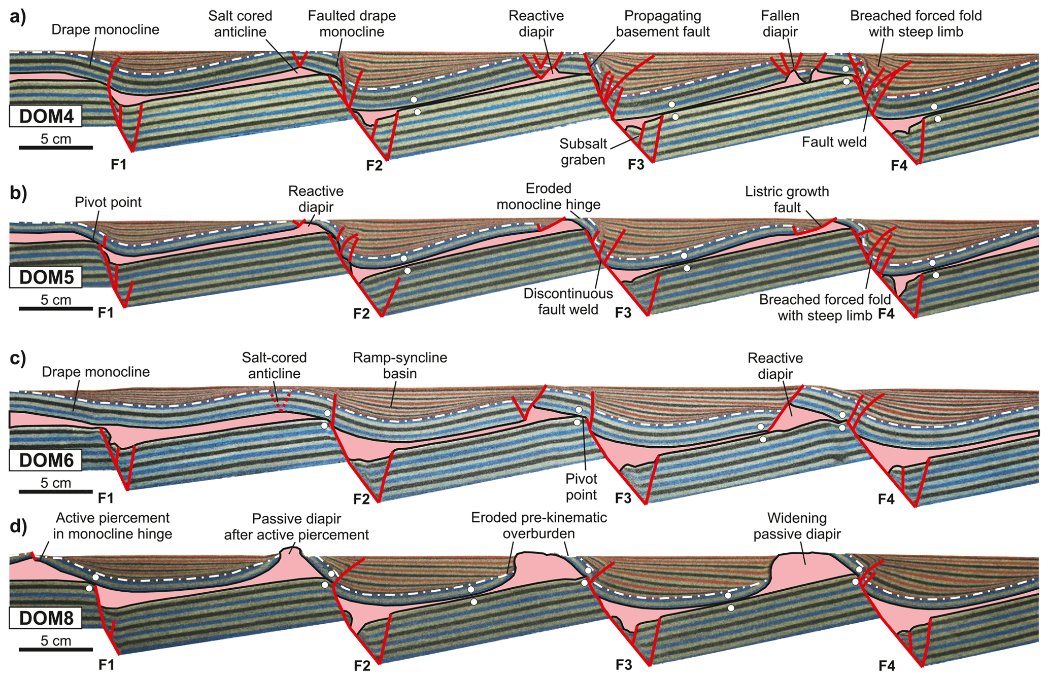
Figure 4Central cross-section of the different extensional experiments illustrating the structural styles developed after 10 cm of extension (see parameters in Table 1) (modified from Ferrer et al., 2023). (a) Model DOM4 (thin polymer, thick pre-kinematic overburden); (b) Model DOM5 (thin polymer, thin pre-kinematic overburden); (c) Model DOM6 (thick polymer, thick pre-kinematic overburden); (d) Model DOM8 (thick polymer, thin pre-kinematic overburden). Note how the ratio between the polymer and pre-kinematic overburden thicknesses results in the development of different salt-related structures but also different salt-detached ramp–syncline basin architectures. The white dashed line indicates the boundary between pre- and syn-extensional units. White dots correspond to primary welds. © AAPG 2023. Reprinted and modified by permission of the AAPG, whose permission is required for further use.
Model DOM5, with a thin polymer and a thin overburden, also develops drape fold monoclines dipping towards the moving wall, but in this case, they are narrower and with a higher dip than in model DOM4 (compare the dips of the drape monoclines above F1 in Fig. 4a and b). As extension progresses, the tilt of the monoclines increases, developing a drape monocline and local salt inflation. Forced folds are breached and a discontinuous fault weld develops between the overburden panel of the fold and the extensional fault plane (Fig. 4b). Like in model DOM4, salt migration develops salt-cored anticlines, but in this case, they are locally eroded. Primary welds develop above the basement faults, pinning deformation above and below the decoupling layer (pivot or weld point sensu Dooley et al., 2003). This triggers the growth of small crestal grabens at the thinned eroded roof of the salt-cored anticlines that rapidly evolve to thin-skinned low-angle basinward-dipping listric faults (Fig. 4b). Like model DOM4, primary welds are developed below the synclinal basins at the hanging wall of faults F2, F3, and F4.
Model DOM6, with a thick polymer and thick overburden, displays a smooth initial topography with the development of drape monoclines above the basement faults and salt-cored anticlines slightly offset with respect to the basement faults due to salt migration (Fig. 4c). As deformation progresses, welding above the basement faults (F2 to F4 in Fig. 4c) favours the nucleation of steeply dipping to vertical faults that breach the monoclines. Like in models DOM4 and DOM5, early extension is partially accommodated by extensional grabens, affecting the pre-kinematic roof of the salt-cored anticlines (F2 in Fig. 4c). Welding enhances the growth of salt-detached basinward-dipping faults, affecting the grabens and isolating asymmetric triangular reactive diapirs at their footwall. The thick pre-kinematic overburden and the sedimentation rate applied to the model inhibit salt piercing, and reactive diapirs are progressively buried (see reactive diapirs above the footwall of F3 and F4 in Fig. 4c). Due to the salt and/or overburden thicknesses, salt welds do not develop below the ramp–syncline basins, and they only grow at the pivot point and at the hanging wall of the salt-detached basinward-dipping fault in rotating block 3 (Fig. 4c).
Finally, model DOM8, with a thick polymer and a thin overburden, displays emergent diapirs flanked by ramp–syncline basins (Fig. 4d). As in the other models, a drape fold is formed above the basement faults at the beginning of the extension (Fig. 4d). However, the dip of the drape fold at the end of the model is the highest of all the models (almost 80∘ dipping basinward at the end of the experiment) (Fig. 4d). The relationship between the salt and pre-kinematic overburden thicknesses favours a quick migration of salt during the early stages of extension and the development of wider and higher salt-cored anticlines than in any other model. This also causes the rise of the pre-kinematic overburden above the fixed regional surface, which is systematically eroded during the deposition of syn-extensional sand layers. Consequently, erosion triggers diapir active rise and piercement followed by passive growth. The lack of salt-detached extensional faults as extension increases is due to the widening of these diapirs accommodating extension (Fig. 4d). Salt welds below the main ramp–syncline basins are favoured by salt migration that in turn enhances the subsidence of those basins. With increasing extension and therefore more salt migration, the welds widen away from the depocentre towards the edges of the fault blocks (Fig. 4d).
3.2 Inversion stage
Model DOM12, which is the inverted equivalent to DOM4 (Table 1), displays all the salt-detached ramp–syncline basins arched and uplifted with crestal collapse grabens developed during inversion (Fig. 5a). This contraction also causes the squeezing of inherited reactive diapirs and the inversion of the grabens (compare structures from Figs. 4a and 5a). All the newly developed footwall thrusts affecting the overburden are foreland-directed (fixed wall of the model). It is interesting how fault welds inherited from the extensional stage are reactivated and reopened during the inversion (Fig. 5a). At the early stages of shortening, reactivation of the inherited extensional basement fault occurs. Moderate inversion creates structural relief by arching and uplifting the ramp–syncline basins. Part of the contractional deformation is also transferred to the foreland by shearing of the salt layer, producing the partial inversion of the hinterland-dipping faults of the graben and minor footwall shortcuts (Fig. 5a). During this process weld reopening occurs due to the impingement of the hanging wall of the basement shortcut to the overburden (Fig. 5a). This can be identified by the shortened length of the welded succession between the overburden and basement above all the faults. In contrast, the location and the length of the primary welds below the ramp–syncline basins barely change during the inversion (compare the welds in Figs. 4a and 5a).
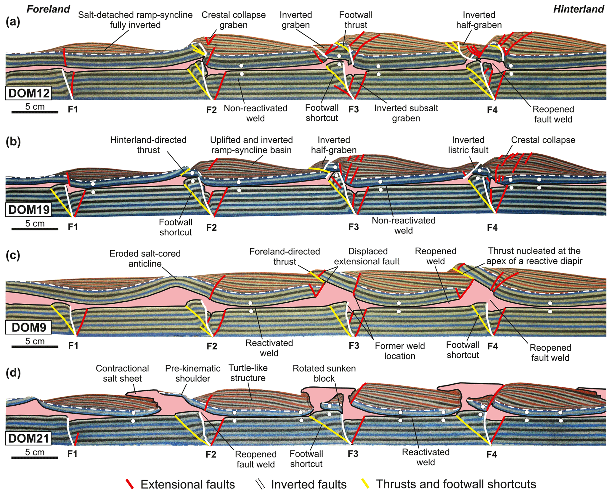
Figure 5Central cross-section of the different compressional experiments illustrating the structural styles developed after total inversion (10 cm of shortening) (see parameters in Table 1). (a) Model DOM12 (thin polymer, thick pre-kinematic overburden); (b) Model DOM19 (thin polymer, thin pre-kinematic overburden); (c) Model DOM9 (thick polymer, thick pre-kinematic overburden); (d) Model DOM21 (thick polymer, thin pre-kinematic overburden). The white dashed line indicates the boundary between pre- and syn-extensional units. White dots correspond to primary welds.
Model DOM19, which is the inverted equivalent to DOM5 (Table 1), displays all the ramp–syncline basins uplifted and completely inverted with crestal collapse graben or extensional normal faults dipping towards the foreland at the outer arch of the sedimentary succession (Fig. 5b). Compressional deformation also produces the inversion of the low-angle basinward-dipping listric faults inherited from the extensional episode. This reactivation either overthrusts part of the pre-kinematic overburden or folds and uplifts the half-grabens at their hanging wall (F2 and F4, respectively, in Fig. 5b). In contrast, the structural style of the inverted half-graben related to F3 is slightly different, and although the inherited listric fault is inverted earlier, it is subsequently decapitated by a foreland-directed thrust (F3 in Fig. 5b). This difference in the structural style can be related to a greater impingement of the hanging wall of the basement shortcut against the overburden. Contrasting with the overburden deformation, the deformation at the basement level is mostly accommodated by the inversion of the main basement fault as well as by the development of footwall shortcuts (Fig. 5b). Note that while the fault welds are partially reactivated during inversion, the primary welds below the basins are not reactivated (compare welds and fault welds distribution in Figs. 4b and 5b).
Model DOM9, which is the inverted equivalent to DOM6 (Table 1), shows a quite different structural style compared to models with a thin salt layer (models DOM12 and DOM19). In this case, the thick salt layer and the thick overburden play a key role in the deformation of the overburden and the geometry of the salt-related structures during inversion. The arching and uplift of the inverted basins at the end of the shortening are lower-amplitude than in the two previous models, and no crestal collapse grabens develop (Fig. 5c). Compressional deformation amplifies the salt-cored anticline above F2 (compare Figs. 4c and 5c). Interesting features of this model are the foreland-directed thrusts that nucleated at the apex of the reactive diapirs and override the syn-extensional sequences of the footwall (F3 and F4 in Fig. 5c). The development of those thrusts and the non-inversion of the inherited extensional faults are controlled by the opposite dip of the salt-detached faults to the shortening direction, the thick overburden, and the triangular shape of the inherited reactive diapirs (Fig. 4c). In addition, the clockwise rotation of the basement blocks during inversion causes the reactivation of primary welds below the different ramp–syncline basins as well as the reactivation and reopening of the inherited fault welds above the main faults (compare the location of primary welds in Figs. 4c and 5c).
Finally, model DOM21 is the inverted equivalent to DOM8 (Table 1). In this extension–inversion pair, salt is exposed at surface at the end of both the extension and the inversion phase, developing passive diapirs and salt sheets (compare Figs. 4d and 5d). Salt migration has an important role in this model as evidenced by the fact that the inherited salt-detached ramp–syncline basins with onlaps at both limbs (Fig. 4d) are displayed as turtle-like structures at the end of the inversion (basins above F1 and F2 in Fig. 5d). The clockwise rotation of the basement blocks during inversion shears and reopens the fault welds at the cutoff of major basement faults, allowing salt migration towards the diapirs as the inherited primary welds below the basins are reactivated and reopened (compare the location and extension of primary welds in Figs. 4d and 5d). The extrusion rate allows the preservation of a thin pre-kinematic shoulder next to the diapir above F2 (Fig. 5d). In contrast, part of the roof above faults F3 and F4 sinks into the salt (Fig. 5d). While some of these collapsed blocks become welded after sinking (F4 in Fig. 5d), others rotate counterclockwise, expelling salt probably during and after sinking (F3 in Fig. 5d).
Our extensional models show that, in general, there is a similar pattern in the development of structures and geometries affecting the overburden (Fig. 4) but with significant differences depending on the ratio between the polymer and overburden thicknesses. Sub-salt extensional half-grabens with antithetic faults are the most prominent structures accommodating extension in the sand unit as the basement blocks rotate. Salt migration occurs in all models, thus conditioning (1) the coupling between basement–overburden and the development of primary welds that compartmentalize the salt layer and (2) the development of salt-related structures. Syn-extensional sand layers are mostly deposited in salt-detached ramp–syncline basins (sensu Roma et al., 2018b, c) that grow at the hanging wall of each fault block (Fig. 4). The internal architecture of the ramp–syncline basins is conditioned by the salt and pre-kinematic thicknesses. The depocentre location of those basins changes abruptly once primary welds develop above the footwall cutoff of the basement faults. Prior to welding, the depocentre trajectory is curved in agreement with the development of a ramp–syncline basin, while after welding, the trajectory trend shifts and becomes linear (see Figs. 4 and 11 of Ferrer et al., 2023). Welding also triggers the development of salt-detached structures at the upper hinge of the adjacent monoclines (Fig. 4).
On the other hand, the inverted models show how inherited extensional basement faults were compressionally reactivated (F1 to F4, in Fig. 5) but also how footwall shortcuts nucleated at the footwall of basement faults (Fig. 5). Arching and uplifting of the ramp–syncline basins were noticed in all the models, and despite the fact that the amount of shortening is the same in all the models (10 cm), the evolution, structural height, and geometry of the uplifted basins are clearly different (Fig. 5). As far salt structures are concerned, these models provide a set of reactivated salt structures by tectonic inversion from which their inherited extensional geometry is well known.
Several questions have arisen after performing the experiments and evaluating the results. Among others, the most important are the following. (a) How does the style of salt-related structures change during inversion? (b) How does the basement configuration under extension condition the distribution of syn-tectonic sediments? (c) How do inversion tectonics impact the salt migration, primary welds kinematics, and the final geometry of the inverted basin? The aim of this section is to provide insights on those questions.
4.1 How does the style of salt-related structures change during inversion?
Salt distribution is a key aspect that should be considered when interpreting the evolution of a basin, especially if it is affected by several stages of deformation (Yin and Groshong, 2006; Rowan and Ratliff, 2012). In our experimental programme, salt migration occurred during the extensional phase, with salt accumulations towards both the hanging wall and the footwall of the basement extensional faults (see Fig. 3 by Ferrer et al., 2023). The counterclockwise rotation of the basement blocks triggered salt migration that in turn controlled the development of salt-detached ramp–syncline basins, the formation of primary and fault welds, the nucleation of salt-detached extensional faults, and the rise and fall of diapirs (Figs. 4 and 6a–d). Although these processes are discussed in depth by Ferrer et al. (2023), here we highlight the most important points of the study in order to underline how the inherited extensional configuration conditions the evolution during tectonic inversion.
The pre-extension configuration of the model was characterized by salt being flat-layered and isopachous (pre-rift). At the beginning of the extension, salt was stretched and migrated towards the footwall and, especially, the hanging wall of the main basement faults (Figs. 4 and 6a–d). Subsidence of ramp–syncline basins expelled the underlaying salt by differential loading (Hudec and Jackson, 2007) and finally touched down, forming a primary weld that enlarged as extension increased and more salt was expelled (Figs. 4 and 6a–d). In addition, drape monoclines developed above each basement fault, and with continued extension welding onto the sub-salt strata resulted in the breaching of these monoclines by faulting (Fig. 4). Relict salt can be trapped at the footwall of antithetic faults along the basement-fault plane, forming discontinuous welds (Fig. 4a and b) (Rowan et al., 2012). Salt is also expelled downward as the syncline basins drag onto the basement fault, forming a composite fault–fault weld surface (Stewart, 2014). If the extension continues, significant shear can be involved along these surfaces.
The inherited structural grain as well as the continuity of the salt layer or its welded equivalent at end of the extension phase highly conditioned the processes and structures developed during inversion. Salt thickness controlled coupling and decoupling between basement and overburden during the contractional deformation (Letouzey et al., 1995). Under compression pre-existing diapirs (i.e. passive diapirs in model DOM8, Fig. 4d), being the weakest part of the models, were squeezed earlier, increasing the salt rise rate. This fact, together with the lack of syn-inversion sedimentation, allowed the emplacement of allochthonous salt sheets in an extrusive advance mode (Hudec and Jackson, 2006) (Fig. 5d). During inversion, buried diapirs were rejuvenated and/or the inherited salt-detached extensional faults above them were inverted (white faults in models DOM12 and DOM19, Fig. 5a and b), or newly formed thrusts nucleated at the apex of the reactive diapirs (yellow faults of the overburden in model DOM9, Fig. 5d) (Roma et al., 2008a). In addition, the thickness of the cover above salt-cored anticlines conditioned the locus of thrusts during inversion, especially if the cover was either already thin or thinned by local erosion during extension (hinterland-directed thrust above F2 in Fig. 5b compared to Figs. 4c and 6f). In contrast, a thick pre-extensional overburden (salt-cored anticlines above F2 in Fig. 4c) confined the salt during the compression and salt accumulations were accentuated (equivalent structures in Figs. 5c and 6g). On the other hand, regional shortening forced the clockwise rotation of the basement blocks (thick-skinned deformation), having a critical impact on the inherited weld distribution that was strongly modified (Fig. 6). Depending on the structural position, welds can be enlarged if they were developed in the central part of basement blocks, but they can also be reopened where basement blocks impinged the overburden in models with a thick salt layer (DOM9 and DOM21, Fig. 5c and d, respectively). This process can be deduced by comparing the location of welds developed during the extensional phase that are either not present at the end of compression or that shifted their location during the inversion phase (Fig. 6–d against Fig. 6e–h).
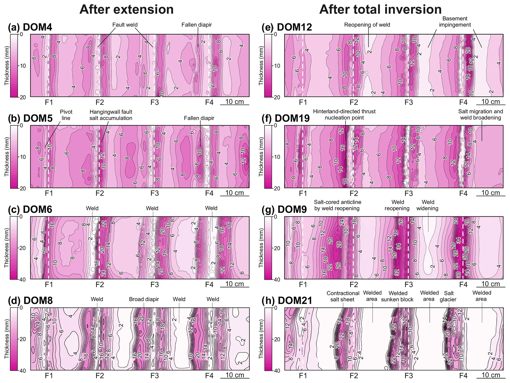
Figure 6Salt isopach maps after extension (a, b, c, d) and after total inversion (e, f, g, h). Notice how the scale range in models DOM6, DOM8, DOM9, and DOM21 (c, d, g, h) is double the range of the other models.
4.2 How does the basement configuration under extension condition the distribution of syn-tectonic sediments?
It is well established that if salt is thick enough, deformation can be decoupled but can also condition the location of newly developed structures at the foreland (e.g. Withjack et al., 1989; Koyi et al., 1993; Jackson and Vendeville 1994; Stewart and Clark, 1999; Withjack and Callaway, 2000; Alves et al., 2002; Dooley et al., 2005; Ferrer et al., 2012, 2016; Duffy et al., 2013; Lewis et al., 2013; Warsitzka et al., 2015; Carola et al., 2017; Jackson et al., 2019; Dooley and Hudec, 2020). This process can be observed in our experiments by comparing the isobath map of the base of salt and the thickness map of the syn-extensional successions (Fig. 7). At a first glance, it is obvious that decoupling occurs since both the thickness maps of the salt and the overburden are different (Figs. 6 and 7) but also by the misalignment in space of the syn-extensional depocentres and the deepest points of the downthrown basement blocks (Fig. 7). More in detail, these parameters present differences that allow even more deeply investigating the impact of salt and cover thickness on the evolution of all models, as discussed below.
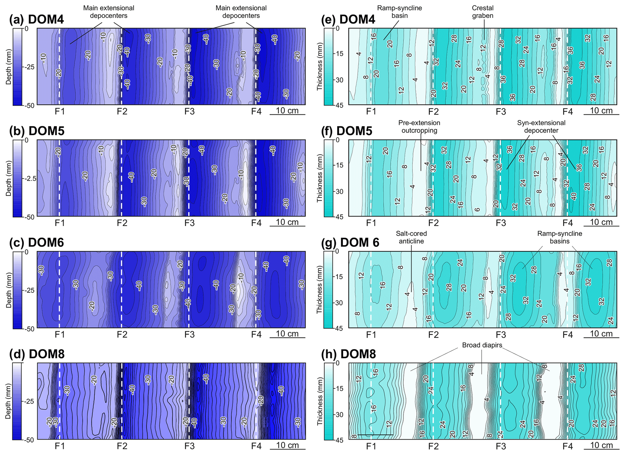
Figure 7Base salt map at the end of extension (a, b, c, d) and isopach maps of the ramp–syncline basin infill at the end of extension (e, f, g).
The base salt maps show that the geometry, at the end of the extension, is quite similar in all the models with tilted panels dipping towards the basement faults (Fig. 7a–d), while the syn-extensional thickness maps show some differences (Fig. 7e–h). A closer inspection of these maps reveals that the base salt maximum depths are located at the hanging wall of basement faults and close to them, with values ranging between −20 mm depth in fault F1 and −45 mm depth in fault F4 (Fig. 7a and b). The accommodation space created by basement extension and the one created by sedimentary loading triggered salt movement, allowing the development of ramp–syncline basins in the overburden. In this process, the key factor controlling the geometry of ramp–syncline basins is the thickness of the salt unit (Fig. 4). Therefore, in models with a thin polymer, the ramp–syncline basins reach thicknesses between 20 and 40 mm close to the basement-fault displacement. In addition, the depocentre trajectory has a linear trend parallel to those of the fault movement (Fig. 7e and f). In these models, deformation is highly coupled, and therefore the impact of salt on overburden deformation is minimal, with the overburden mimicking the basement structure (compare Fig. 7a–b and e–f, respectively). In contrast, ramp–syncline basins of models with a thick polymer are slightly thinner, between 16 mm in fault F1 and 32 mm in fault F4 (Fig. 7h and g). In this case, the deformation behaves as fully decoupled, and the impact of the salt thickness on the overburden deformation is strong (Fig. 4c and d).
All the described extensional geometries can be attributed to the decoupling level that provides the polymer by simply comparing these geometries with the ones developed under the same parameters but with models lacking the polymer such as the ones performed by Buchanan and McClay (1992) and by Jagger and McClay (2018). The results from the extensional models of these authors show how the location of the main depocentres is immediately above the basement extensional faults and with a depocentre trajectory that is parallel to the main fault (Fig. 2a of Buchanan and McClay, 1992 or Fig. 4a of Jagger and McClay, 2018). In contrast, the models reported by Ferrer et al. (2023) and here show how the location of the depocentres is highly conditioned by the thickness ratio of salt vs. overburden and that they are not located immediately above the main extensional faults. In addition, through time, the trajectory of the salt-detached ramp–syncline depocentres is not linear but curved, thus recording the salt migration process that occurs as extension progresses (Fig. 4).
4.3 How does inversion affect salt migration, primary welds, and the final geometry of the inverted basin?
Previous works using similar experimental apparatus but without mechanical anisotropies show how inherited basement extensional faults reactivate as reverse faults during the inversion and new shortcuts develop at their footwalls (Figs. 2–6 of Buchanan and McClay, 1992, or Figs. 4–9 of Jagger and McClay, 2018). In contrast, in this research, the contractional deformation is partitioned by the viscous polymer layer. Thick-skinned deformation reactivated basement structures and developed shortcuts (F1 to F4 white basement faults in Fig. 5), while the overburden is thin-skinned deformed as in the experiments of Ferrer et al. (2016) or Dooley and Hudec (2020). Foreland- and hinterland-directed thrusts (Fig. 5c and b, respectively), compressionally amplified salt-cored anticlines (Fig. 5c), and salt sheets (Fig. 5d) are the main salt-related structures. In addition, a correlation between polymer thickness and overburden structural relief has been observed in the experiments. Independently of the pre-kinematic overburden thickness, the thinner the polymer the higher the structural relief (Fig. 8). Therefore, the role that the salt layer plays in the development of structural relief is related to the degree of decoupling between sub- and supra-salt units. As pointed out before, the structures will depend on the ratio between polymer and overburden thicknesses, and consequently, in natural cases, the thickness of the decoupling layer must be considered when interpreting either the actual geometry of inverted basins when deriving the evolution of a basin or the evolution during inversion. For that reason, the following subsections discuss the behaviour of primary welds and the basin configuration at the end of inversion.
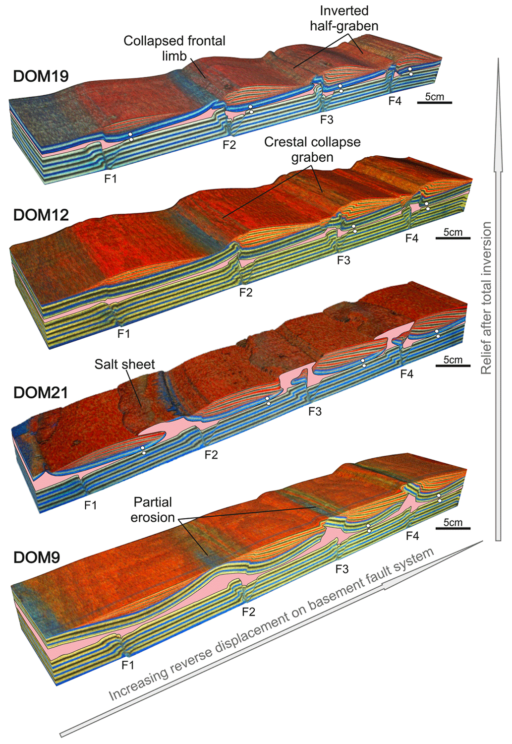
Figure 83D voxels of DOM19, DOM12, DOM21, and DOM9 displaying the effect that the decoupling layer is having in the development of overburden structural relief after total inversion. Notice how faults close to the moving wall display more reverse displacement due to the apparatus design.
4.3.1 How do extension and inversion impact weld kinematics?
One of the processes observed during inversion was the shearing and reopening of inherited primary welds. Reopening of these salt-depleted mechanical contacts is clearly seen when comparing salt thicknesses at the end of the extensional and the compressional stages (Fig. 9). Mapping the welded areas both after extension and after inversion shows that their location is not perfectly aligned or that some welds even developed under extension not being present at the end of inversion (Fig. 9a). For simplicity, the location of welds at the end of extension has been split into two different groups in this figure. The first group includes welds developed immediately on the sub-salt footwall cutoff of the basement fault (pivot or weld point sensu Dooley et al., 2003) (Fig. 9b), whereas the second group includes welds developed below the salt-detached ramp–syncline basins (Fig. 9c). The first group of welds is developed at the pivot point of the footwall cutoff of the basement faults. Once the weld is generated, with increasing extension, the weld enlarges because salt is gradually expelled downward as the overburden rolls onto the basement-fault plane enhanced by the counterclockwise rotation of basement blocks (Fig. 9b). In addition, when the weld is developed, the decoupling between the overburden and the basement is inhibited, causing the development of a basinward-dipping salt-detached extensional fault and a reactive diapir at the overburden succession located above the footwall cutoff of the basement fault (Figs. 4 and 9b). This overburden fault is developed in order to accommodate extension produced by the adjacent down-dip basement fault. As Steward (2014) proposed, the coupling between the basement and the overburden also allows the reactivation of the weld developed above the basement fault as a fault weld with increasing extension (Fig. 4). The second group of welds develops when the sinking ramp–syncline basins touch down to the basement and gradually expand, both up- and down-dip, with increasing extension and salt expulsion (Fig. 9c). This results in the salt migration feeding the reactive diapir developed at the footwall of the overburden basinward-dipping salt-detached extensional fault at the up-dip section (Fig. 9c). In contrast, at the down-dip section, the expelled salt feeds the salt accumulation developed next to the basement fault (Fig. 9c). During the inversion, the clockwise rotation of the basement blocks forces the reopening of both groups of inherited primary welds from the hinterland towards the foreland as seen by the shift in weld locations between extension and inversion stages (Fig. 9a and c). This process, which is discussed below, is common in models wherein decoupling is more accentuated, and therefore models with thicker polymer successions are more prone to reactivating this type of weld under compression (DOM9 of Fig. 5).
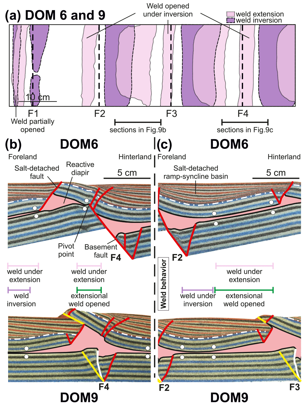
Figure 9Weld reactivations. (a) Map overlapping the weld distribution after extension and inversion. (b) Weld reactivation example located above a basement extensional fault. (c) Weld reactivation example located below the salt-detached ramp–syncline basin. See Fig. 5 for fault labelling.
The reopening of extensional fault welds is a continuous process that involves the inversion of the former extensional basement fault as well as block rotation above and below the salt (Fig. 10). The pre-inversion configuration is characterized by the coalescence of the two previously described welds (Fig. 10a). Once shortening initiates, inversion of the basement fault starts to uplift the whole hanging wall succession, and rotation of the basement block occurs. At this mild inversion stage, both welds are still closed, and inversion is evidenced by the development of a foreland-directed thrust generating some structural relief that remains active until the end of compression (Fig. 10b to d). As inversion progresses, the fault weld is reopened, thus connecting the two salt accumulations developed during the extensional stage and allowing the salt to flow between the two accumulations (Fig. 10c). This explains why some of the welded areas under extension are not present at the end of the inversion as shown in Fig. 9a. In addition, salt flow is enhanced by the counterclockwise rotation of the ramp–syncline basin, thus causing the reopening of the weld developed below the basin, and the newly generated space is filled by salt (Fig. 10c). During this stage, sub-salt compression is partially absorbed by the reverse movement of the former basement extensional fault but also by the development of footwall shortcuts. Finally, total inversion is characterized by the almost horizontal disposition of sub-salt strata, the total reopening of the fault weld, and an active process of weld reopening and salt migration as the ramp–syncline basin continues to rotate (Fig. 10d).
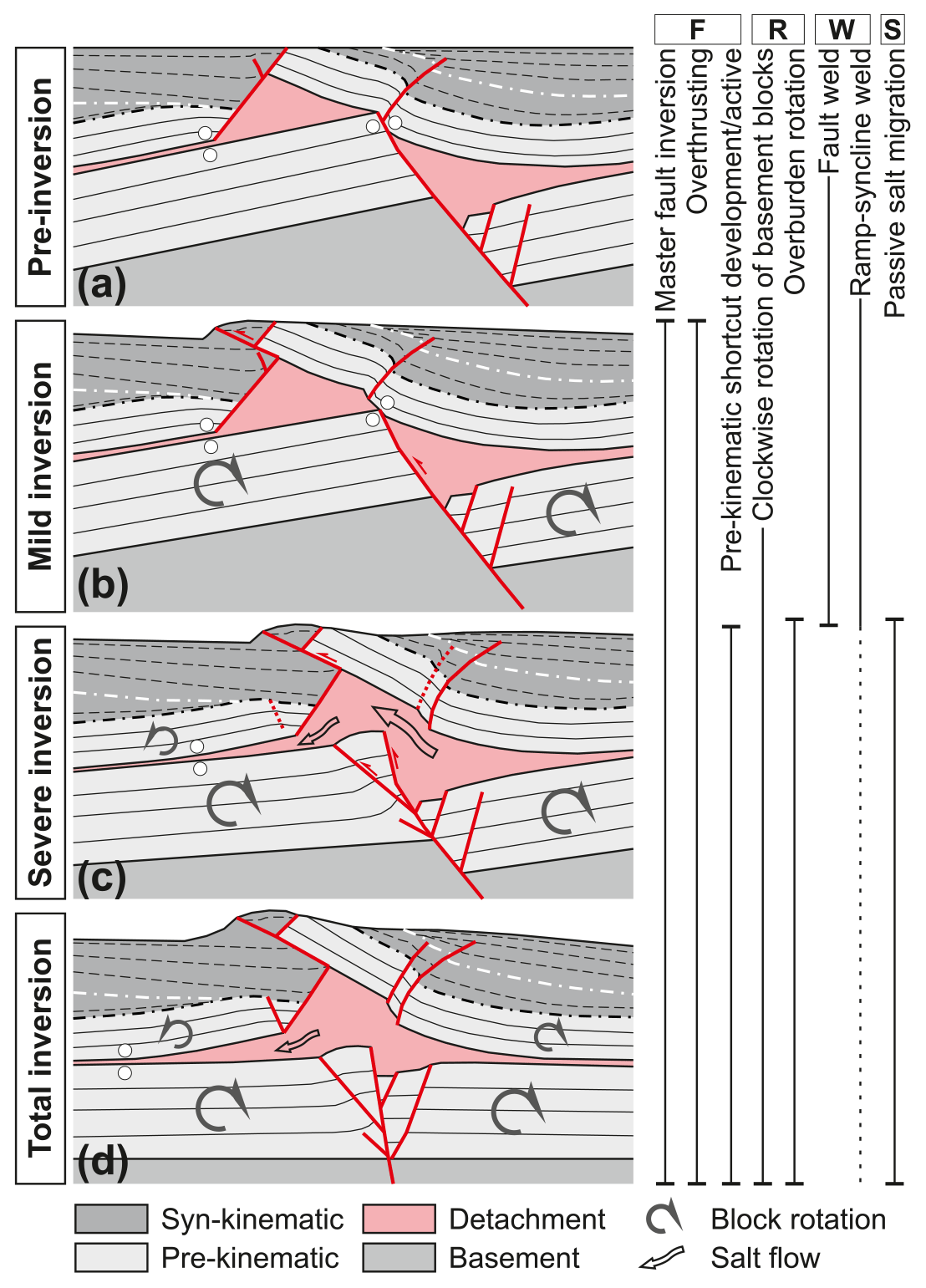
Figure 10Sequential evolution of weld reopening from the post-extensional configuration to total inversion of a fault weld: case example from experiment DOM9. The letters F, R, W, and S above the different processes correspond to fault (F), rotations of sedimentary blocks (R), welds (W), and salt migration (S).
This process is more accentuated in models with a thick polymer layer since decoupling is also more accentuated. In contrast, in models with a thin polymer layer, reopening hardly occurs, as shown by the preservation of the inherited weld at the pivot point at the end of compression (Figs. 5a–b and 6e–f). It is important to remark that in the models, as in nature, it is not the salt that reopens the welds, but rather the basement blocks involved in the compressional deformation that do the active work (thick-skinned deformation). The role of salt is passive and twofold: (1) it flows and occupies the space generated during the rotation of blocks, and (2) it acts as a decoupling layer, allowing the overlying basins to accommodate the thick-skinned deformation. It is also worth mentioning that the confinement of the salt and the non-existence of inherited salt structures (i.e. diapirs and walls) could play a major role in conditioning weld reopening. A well-developed network of diapirs, inherited from the extensional episode, could inhibit the reopening of welds since they would be preferentially squeezed at the onset of the compressional deformation developing salt sheets (Dooley et al., 2009; Santolaria et al., 2021). Once most of these diapirs were secondarily squeezed and depending on the volume of preserved salt in the source layer, the primary welds could be reopened. This is a factor that has not been tested in the current research, and it is worth considering in future models.
Although our experiments shows how primary welds inherited from an extensional episode reopened during subsequent thick-skinned contractional deformation, to our knowledge, the process that leads to weld reopening has not been described in the literature in real cases or in analogue or numerical models, and therefore, this research provides new insights on weld reactivation which should be considered in the future. The closest process would correspond to salt delamination of deep salt wings described originally in the northwestern German and Polish basins (Baldschuhn et al., 1991; Rowan and Krzywiec, 2014). According to Hudec (2004), in that case, the Late Cretaceous regional shortening produced the injection and intrusion of the deeper Permian Zechstein and Rotliegend salt into shallower Triassic Röt salt, forming wings on the flanks of many salt diapirs of the area. Rowan and Krzywiec (2014) point out that compressional deformation was not responsible for salt being injected into the wings. Rather, they reported that the process must be viewed as a passive flow into the space created during folding and uplift of the flanking strata adjacent to the diapirs during the squeezing of buried diapirs by regional shortening. Dooley et al. (2009) described a similar process in analogue models by simulating deeply buried diapirs that were subsequently compressionally rejuvenated. According to this work, the space generated by the uplift of the footwall thrust allowed salt to flow back into the source layer during the squeezing of a deeply buried diapir by a thick roof defining an outward intrusive plume (see Fig. 9 of Dooley et al., 2009). In our opinion, in this case, the use of the term intrusion would not be appropriate since salt is only passively flowing towards the new space created by cover uplift during regional shortening. In our thick salt models, the welds below the ramp–syncline basins are reopened due to the rotation of basement blocks, which are decoupled from the cover by the salt layer, delaminating and generating new space passively occupied by salt. Similarly, thick-skinned inversion is the active mechanism for welds reopening above basement faults (Fig. 11). Nevertheless, in this case, the two salt volumes separated by a primary weld at the end of the extension (Fig. 4c and d) are connected again during inversion, allowing the flow of salt (Fig. 5c and d). The reopening of those welds is not suitable for the delamination process since the control of the vertical movements of the basement blocks during inversion is critical in this case. Thick-skinned contractional deformation is the motor that controls weld reopening and salt merely flows into the newly created spaces.
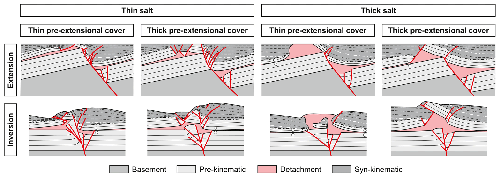
Figure 11Summary figure displaying the different salt-related structural styles that resulted from extension and inversion of the different experimental configurations. Notice how the thickness of the salt layer (or its welded equivalent) conditions the coupling or decoupling of the overburden succession, thus conditioning the structural style.
4.3.2 What is the final geometry of the basin at the end of the inversion stage?
Finally, of interest is the geometry of the ramp–syncline basins at the end of the compressional stage and how it relates to the initial thickness of salt. In all the cases with a thin polymer succession, a total inversion of the basin is observable (Fig. 5a and b), whereas in models with a thick polymer, the resultant geometry of the ramp–syncline basins does not show a total basin inversion; rather, only partial inversion is documented (Fig. 5c and d). In the models with a thick polymer and a thick overburden, the hinterland basins are slightly rotated and thrust over the more external basins, while the basins located in a more foreland position preserved the extensional geometry. In these models, deformation is absorbed by the salt migration into thickened salt-cored anticlines and uplifting of the overburden (Fig. 5c). The preservation of the extensional geometries pre-dating the development of fold-and-thrust belts is rather common as reported in several basins that underwent partial inversion and in orogens around the world such as the Apennines, the Pyrenees, or the Betics (Scisciani et al., 2014; Carola et al., 2015; Saura et al., 2016; Escosa et al., 2018). On the other hand, models with a thick polymer and a thin overburden sequence are characterized by geometries grown during the inversion stage related to salt migration processes, which developed turtle structures, but also by the generation of salt sheets or salt glaciers (Fig. 5d). Similar processes have been described in Gabon, Morocco, and the sub-Alpine fold-and-thrust belt where compressional salt glaciers developed during the growth of the orogen (Ventisette et al., 2005; Hudec and Jackson, 2006; Jackson et al., 2008; Graham et al., 2012; Fernández et al., 2020; Flinch and Soto, 2022).
While a thin salt results in a more coupled deformational style during both extension and inversion (Fig. 11), the opposite occurs when the salt is thick, and therefore a completely decoupled deformation is observed (Fig. 11). This behaviour has long been reported in several works based on analogue modelling (e.g. Jackson and Vendeville, 1994; Jackson et al., 1994; Withjack and Callaway, 2000; Withjack et al., 2000; Dooley et al., 2003, 2005; Bonini et al., 2012; Ferrer et al., 2014, 2023; Roma et al., 2018a; Dooley and Hudec, 2020). In the model with a thin salt and thin pre-extensional cover, the geometries after extension are characterized by a short and steeply dipping monocline which develops a long fault weld and, above the monocline, an extensional basin located close to the basement extensional fault (Fig. 11). The geometries after total inversion are characterized by the preservation of the basement impingement and by the total inversion of the syn-extensional succession with collapse faults affecting this succession (Fig. 11). In the model with a thick salt and pre-extensional successions, the geometries after extension are different depending on the thickness of the pre-extensional overburden. If it is thin, passive diapirs develop by erosion of a salt-inflated area, and therefore most of the extension is accommodated within these structures (Fig. 11). In contrast, a thick cover results in the development of reactive diapirs that in the experiments ended up as buried salt accumulations (Fig. 11). Although the geometries and processes are different, in both cases there is the development of a large monocline, the growth of an extensional basin above the monocline whose depocentre is not located close to the main basement fault, and a less important basement impingement compared to the previous case. The geometries after total inversion are also different depending on the cover thickness, and for a reduced cover, the most common geometry is the preservation of some of the outcropping salt structures and the development of salt sheets, whereas with a thick cover, the reopening of welds and the development of foreland-directed thrusts are the most important structures absorbing shortening (Fig. 11).
This study focused on revealing the implications accounted for during the inversion of domino extensional basement-fault systems with pre-extensional salt by means of analogue modelling. The experimental results provide a useful tool when working in those areas because the resultant geometries can be categorized depending on the different thicknesses of both the salt and the pre-extensional cover.
The ratio between polymer and overburden thicknesses highly conditioned the evolution of the former extensional basins under compression. The amount of structural relief during the inversion is directly related to the thickness of both the syn-extensional deposition and the polymer layer. The thicker the polymer and overburden successions, the smaller the structural relief. In contrast, when the polymer layer and the overburden are the thinner, the resultant structural relief is higher. This is related to the coupling or decoupling between basement and overburden, and therefore, when they are highly coupled, inversion of basement faults focuses uplift of the overburden, thus increasing the structural relief.
Our study characterizes how inherited weld reopening occurs during the compressional episode. Even though weld reopening under compression occurs to a greater or lesser extent in all models, the results show that the welds developed in models with thick salt and syn-extensional successions are the most likely to be reactivated and reopened. During extension, welds were developed either below the salt-detached ramp–syncline basins or immediately above the basement faults. In the former case, the weld developed during extension by salt migrating towards the adjacent hanging wall and footwall of basement faults. During the compressional episode, the weld is partially reactivated, reopening towards the hinterland due to the counterclockwise rotation of the overburden, and at the same time, it is enlarged towards the foreland. In the latter case, the extensional weld was generated due to salt migration as well as sagging of the overburden at the footwall cutoff point. During inversion, the weld reopens, thus connecting the two salt accumulations and allowing the salt to flow again, thereby resulting in there being no record of the inherited extensional weld at the end of the compression.
Uninterpreted images of the final cross-sections of the extensional and inverted models included in this work are freely available in a data publication stored by Harvard Dataverse (Ferrer and Carola, 2023, https://doi.org/10.7910/DVN/A52MVH, Harvard Dataverse, V1).
OF and KM were involved in the conceptualization of the experimental programme and organized the funding acquisition and the administration of the project. OF performed the experiments and developed the methodology. The interpretation of the dataset, preparation of the original draft, figure design, reviews, and editing of the paper were carried by OF and EC.
The contact author has declared that none of the authors has any competing interests.
Publisher's note: Copernicus Publications remains neutral with regard to jurisdictional claims in published maps and institutional affiliations.
This article is part of the special issue “Analogue modelling of basin inversion”. It is not associated with a conference.
This work has been partly supported by the SABREM (PID2020-117598GB-I00) and GEODIGIT (TED2021-130602B-I00) research projects funded by MCIN/AEI/10.13039/501100011033 for the European Union “NextGenerationEU”/PRTR, as well as by the STAR Research Consortium (supported by BG Group, BHPBilliton, ConocoPhillips, ENI, MarathonOil, Nexen, Shell, Talisman Energy, and YPF). The GEOMODELS Research Institute and the Grup de Geodinàmica i Anàlisi de Conques (grant no. 2021SGR76) are also acknowledged for their financial support. The models presented in this work are part of OF's postdoc at the Earth Science Department of the Royal Holloway University of London. Kevin D'Souza, Jerry Morris, and Frank Lehane are gratefully acknowledged for logistical support in the modelling laboratory. We thank Mark G. Rowan, Bruno C. Vendeville, and Simon Stewart for helpful discussions and suggestions. Schlumberger and Eliis are also acknowledged for providing Petrel and PaleoScan software, respectively. We would finally like to thank Tim Dooley and Timothy Schmid for their helpful reviews and Guido Schreurs for handling the paper.
This research is part of the PID2020-117598GB-I00 R+D+i and TED2021-130602B-I00 projects funded by MCIN/AEI/10.13039/501100011033 as well as the European Union “NextGenerationEU”/PRTR. It was initially funded by the STAR Reseach Consortium (supported by BG Group, BHPBilliton, ConocoPhillipd, ENI, MarathonOil, Nexen, Shell, Talisman Energy and YPF). Part of this research has also been supported by the Grup de Recerca de Geodinàmica i Anàlisi de Conques (grant no. 2021SGR76).
This paper was edited by Guido Schreurs and reviewed by Tim Dooley and Timothy Schmid.
Alves, T. M., Gawthorpe, R. L., Hunt, D. W., and Monteiro, J. H.: Jurassic tectono-sedimentary evolution of the Northern Lusitanian Basin (offshore Portugal), Mar. Petrol. Geol., 19, 727–754, https://doi.org/10.1016/S0264-8172(02)00036-3, 2002.
Badley, M. E., Orice, J. D., and Backshall, L. C.: Inversion, reactivated faults and related structures: seismic examples from the southern North Sea, edited by: Cooper, M. A. and Williams, G. D., Inversion Tectonics, Geol. Soc. Spec. Publ., 44, 201–219, https://doi.org/10.1144/GSL.SP.1989.044.01.12, 1989.
Baldschuhn, R., Best, G., and Kockel, F.: Inversion tectonics in the north-west German basin, in: Generation, accumulation, and production of Europe's hydrocarbons, edited by: Spencer, A. M., Springer, European Association of Petroleum Geoscientists, Special Publication 1, 149–159, ISBN 978-0198542827, 1991.
Bally, A. W.: Tectogénèse et seismique réflexion, Bulletin Société Géologique de France, 23, 279–285, https://doi.org/10.2113/gssgfbull.S7-XXVI.2.279, 1984.
Bonini, M., Sani, F., and Antonielli, B.: Basin inversion and contractional reactivation of inherited normal faults: A review based on previous and new experimental models, Tectonophysics, 522–523, 55–88, https://doi.org/10.1016/j.tecto.2011.11.014, 2012.
Brun, J. P. and Fort, X.: Compressional salt tectonics (Angolan margin), Tectonophysics, 382, 129–150, https://doi.org/10.1016/j.tecto.2003.11.014, 2004.
Brun, J. P. and Nalpas, T.: Graben inversion in nature and experiments, Tectonics, 15, 677–687, https://doi.org/10.1029/95TC03853, 1996.
Buchanan, P. and McClay, K. R.: Experiments on basin inversion above reactivated domino faults, Mar. Petrol. Geol., 9, 486–500, https://doi.org/10.1016/0264-8172(92)90061-I, 1992.
Burliga, S., Koyi, H. A., and Krzywiec, P.: Modelling cover deformation and decoupling during inversion, using the Mid- Polish Trough as a case study, J. Struct. Geol., 42, 62–73, https://doi.org/10.1016/j.jsg.2012.06.013, 2012.
Callot, J. P., Jahani, S., and Letouzey, J.: The role of pre-existing diapirs in fold and thrust belt development, in: Thrust belts and foreland basins: From fold kinematic to hydrocarbon systems, edited by: Lacombe, O., Lavé, J., Vergés, J., and Roure, F., 309–325, https://doi.org/10.1007/978-3-540-69426-7_16, 2007.
Carola, E., Muñoz, J. A., and Roca, E.: The transition from thick-skinned to thin-skinned tectonics in the Basque-Cantabrian Pyrenees: The Burgalesa Platform and surroundings, Int. J. Earth Sci., 104, 2215–2239, https://doi.org/10.1007/s00531-015-1177-z, 2015.
Carola, E., Ferrer, O., Vidal-Royo, O., and Muñoz, J. A.: Interpretation of salt-cored frontal structures in the Southern Pyrenees guided by analog modeling, surface and subsurface data, Interpretation, 5, 39–54, https://doi.org/10.1190/INT-2016-0093.1, 2017.
Costa, E. and Vendeville, B. C.: Experimental insights on the geometry and kinematics of fold-and-thrust belts above weak, viscous evaporitic décollement, J. Struct. Geol., 24, 1729–1739, https://doi.org/10.1016/S0191-8141(01)00169-9, 2002.
Couzens-Schultz, B. A., Vendeville, B. C., and Wiltschko, D. V.: Duplex style and triangle zone formation: insights from physical modelling, J. Struct. Geol., 25, 1623–1644, https://doi.org/10.1016/S0191-8141(03)00004-X, 2003.
Davy, P. and Cobbold, P. R.: Indentation tectonics in nature and experiment. 1. Experiments scaled for gravity, Bulletin of the Geological Institutions of Uppsala, N.S., 14, 129–141, 1988.
Davy, P. and Cobbold, P. R.: Experiments on shortening of a 4-layer model of the continental lithosphere, Tectonophysics, 188, l–25, https://doi.org/10.1016/0040-1951(91)90311-F, 1991.
Dell'Ertole, D. and Schellart, W. P.: The development of sheath folds in viscously stratified materials in simple shear conditions: an analogue approach, J. Struct. Geol., 56, 129–141, https://doi.org/10.1016/j.jsg.2013.09.002, 2013.
Dooley, T. P. and Hudec, M. R.: Extension and inversion of salt-bearing rift systems, Solid Earth, 11, 1187–1204, https://doi.org/10.5194/se-11-1187-2020, 2020.
Dooley, T. P., McClay, K. R., and Pascoe, R.: 3D analogue models of variable displacement extensional faults: applications to the Revfallet Fault system, offshore mid-Norway, Geol. Soc. Spec. Publ., 212, 151–167, https://doi.org/10.1144/GSL.SP.2003.212.01.10, 2003.
Dooley, T. P., McClay, K. R., Hempton, M., and Smit, D.: Salt tectonics above complex basement extensional fault systems: Results from analogue modelling, in: Petroleum geology: North-west Europe and global perspectives – Proceedings of the 6th Petroleum Geology Conference, edited by: Dore, A. G. and Vining, B. A., London, Petroleum Geology Conferences Ltd. and the Geological Society, 1631–1648, https://doi.org/10.1144/006163, 2005.
Dooley, T. P., Jackson, M. P. A., and Hudec, M. R.: Inflation and deflation of deeply buried salt stocks during lateral shortening, J. Struct. Geol., 31, 582–600, https://doi.org/10.1016/j.jsg.2009.03.013, 2009.
Dooley, T. P., Jackson, M. P. A., and Hudec, M. R.: Breakout of squeezed stocks: dispersal of roof fragments, source of extrusive salt and interaction with regional thrust faults, Basin Res., 26, 1–23, https://doi.org/10.1111/bre.12056, 2014.
Duffy, O. B., Gawthorpe, R. L., Docherty, M., and Brocklehurst, S. H.: Mobile evaporite controls on the structural style and evolution of rift basins: Danish Central Graben, North Sea, Basin Res., 25, 310–330, https://doi.org/10.1111/bre.12000, 2013.
Escosa, F. O., Roca, E., and Ferrer, O.: Testing thin-skinned inversion of a prerift salt-bearing passive margin (Eastern Prebetic Zone, SE Iberia), J. Struct. Geol., 109, 55–73, https://doi.org/10.1016/j.jsg.2018.01.004, 2018.
Fernández, O., Habermüller, M., and Grasemann, B.: Hooked on salt: Rethinking Alpine tectonics in Hallstatt (Eastern Alps, Austria), Geology, 49, 325–329, https://doi.org/10.1130/G47981.1, 2020.
Ferrer, O. and Carola, E.: Solid Earth_Inversion of a domino-style with pre-extensional salt analogue modelling sections, Harvard Dataverse V1 [data set], https://doi.org/10.7910/DVN/A52MVH, 2023.
Ferrer, O., Jackson, M. P. A., Roca, E., and Rubinat, M.: Evolution of salt structures during extension and inversion of the Offshore Parentis Basin (Eastern Bay of Biscay), Geol. Soc. Spec. Publ., 363, 361–380, https://doi.org/10.1144/SP363.16, 2012.
Ferrer, O., Roca, E., and Vendeville, B. C.: The role of salt layers in the hangingwall deformation of kinked-planar extensional faults: Insights from 3D analogue models and comparison with the Parentis Basin, Tectonophysics, 636, 338–350, https://doi.org/10.1016/j.tecto.2014.09.013, 2014.
Ferrer, O., McClay, K. R., and Sellier, N.: Influence of fault geometries and mechanical anisotropies on the growth and inversion of hangingwall synclinal basins: Insights from sandbox models and natural examples, Geol. Soc. Spec. Publ., 439, 487–509, https://doi.org/10.1144/SP439.8, 2016.
Ferrer, O., Santolaria, P., Muñoz, J. A., Granado, P., Roca, E., Gratacós, O., and Snidero, M.: Analogue modeling as a tool to assist seismic structural interpretation in the Andean fold-and-thrust belt, in: Andean Structural Styles: A Seismic Atlas, Elsevier, edited by: Zamora, G. and Mora, A., 43–61, https://doi.org/10.1016/B978-0-323-85175-6.00003-1, 2022.
Ferrer, O., Carola, E., McClay, K. R., and Bufaliza, N.: Analog modeling of domino-style extensional basement fault systems with pre-kinematic salt, AAPG Bull., 107, 23–47, https://doi.org/10.1306/08072221188, 2023.
Flinch, J. F. and Soto, J. I.: Structure and Alpine tectonic evolution of a salt canopy in the western Betic Cordillera (Spain), Mar. Petrol. Geol., 143, 105782, https://doi.org/10.1016/j.marpetgeo.2022.105782, 2022.
Gowers, M., Holtar, E., and Swensson, E.: The structure of the Norwegian Central Trough (Central Graben area), Geological Society, London, Petroleum Geology Conference series, 4, 1245–1254, https://doi.org/10.1144/0041245, 1993.
Graham, R., Jackson, M., Plicher, R., and Kilsdonk, B.: Allochthonous salt in the sub-Alpine fold–thrust belt of Haute Provence, France, Geol. Soc. Spec. Publ., 363, 595–615, https://doi.org/10.1144/SP363.30, 2012.
Granado, P., Ruh, J. B., Santolaria, P., Strauss, P., and Muñoz, J. A.: Stretching and contraction of extensional basins with pre-rift salt: A numerical modeling approach, Front Earth Sci., 9, 648937, https://doi.org/10.3389/feart.2021.648937, 2021.
Hammerstein, J., Truelove, L., and McClay, K. R.: Additional methods for the analysis of seismic data and risk reduction through the interpretation and reservoir modelling of scaled analogue models, https://www.searchanddiscovery.com/abstracts/html/2014/90189ace/abstracts/1841538.html (last access: 11 July 2022), 2014.
Hansen, T. H., Clausen, O. R., and Andresen, K. J.: Thick- and thin-skinned basin inversion in the Danish Central Graben, North Sea – the role of deep evaporites and basement kinematics, Solid Earth, 12, 1719–1747, https://doi.org/10.5194/se-12-1719-2021, 2021.
Hubbert, M. K.: Theory of scaled models as applied to the study of geological structures, Geol. Soc. Am. Bull., 48, 1459–1520, https://doi.org/10.1130/GSAB-48-1459, 1937.
Hudec, M. R. and Jackson, M. P. A.: Advance of allochthonous salt sheets in passive margins and orogens, AAPG Bull., 90, 1535–1564, https://doi.org/10.1306/05080605143, 2006.
Hudec, M. R. and Jackson, M. P. A.: Terra infirma: Understanding salt tectonics, Earth-Sci. Rev., 82, 1–28, https://doi.org/10.1016/j.earscirev.2007.01.001, 2007.
Jackson, C. A.-L., Chua, C.-T., Bell, R. E., and Magee, C.: Structural style and early stage growth of inversion structures: 3D seismic insights from the Egersund Basin, offshore Norway, J. Struct. Geol., 46, 167–185, https://doi.org/10.1016/j.jsg.2012.09.005, 2013.
Jackson, C. A.-L., Elliott, G. M., Royce-Rogers, E., Gawthrope, R. L., and Aas, T. E.: Salt thickness and composition influence rift structural style, northern North Sea, offshore Norway, Basin Res., 31, 514–538, https://doi.org/10.1111/bre.12332, 2019.
Jackson, M. P. A. and Vendeville, B. C.: Regional extension as a geologic trigger for diapirism, Geol. Soc. Am. Bull., 106, 57–73, https://doi.org/10.1130/0016-7606(1994)106<0057:REAAGT>2.3.CO;2, 1994.
Jackson, M. P. A., Vendeville, B. C., and Schultz-Ela, D. D.: Structural dynamics of salt systems, Annu. Rev. Earth Pl. Sc., 22, 93–117, https://doi.org/10.1146/annurev.ea.22.050194.000521, 1994.
Jackson, M. P. A., Hudec, M. R., Jannette, D. C., and Kilby, R. E.: Evolution of the Cretaceous Astrid thrust belt in the ultradeep-water Lower Congo Basin, Gabon, AAPG Bull., 92, 487–511, https://doi.org/10.1306/12030707074, 2008.
Jagger, L. J. and McClay, K. R.: Analogue modelling of inverted Domino-style Basement Fault Systems, Basin Res., 30, 363–381, https://doi.org/10.1111/bre.12224, 2018.
Koyi, H. A., Jenyon, M. K., and Petersen, K.: The effect of basement faulting on diapirism, J. Struct. Geol., 16, 285–312, https://doi.org/10.1111/j.1747-5457.1993.tb00339.x, 1993.
Krantz, R. W.: Measurements of friction coefficients and cohesion for faulting and fault reactivation in laboratory models using sand and sand mixtures, Tectonophysics, 188, 203–207, https://doi.org/10.1016/0040-1951(91)90323-K, 1991.
Lacombe, O. and Bellahsen, N.: Thick-skinned tectonics and basement-involved fold-thrust-belts. Insights from selected Cenozoic orogens, Geol. Mag., 153, 1–48, https://doi.org/10.1017/S0016756816000078, 2016.
Letouzey, J., Colleta, B., Vially, R., and Chermette, J. C.: Evolution of salt-related structures in compressional settings, AAPG Memoir., 65, 41–60, https://doi.org/10.1306/M65604C3, 1995.
Lewis, M. M., Jackson, C. A.-L., and Gawthorpe, R. L.: Salt-influenced normal fault growth and forced folding: the Stavanger Fault System, North Sea, J. Struct. Geol., 54, 156–173, https://doi.org/10.1016/j.jsg.2013.07.015, 2013.
Lohrmann, J., Kukowski, N., Adam, J., and Oncken, O.: The impact of analogue material properties on the geometry, kinematics and dynamics of convergent sand wedges, J. Struct. Geol., 25, 1691–1711, https://doi.org/10.1016/S0191-8141(03)00005-1, 2003.
Nemčok, M., Gayer, R., and Miliorizos, R.: Structural analysis of the inverted Bristol Channel Basin: implications for the geometry and timing of fracture porosity, Geol. Soc. Spec. Publ., 88, 355–392, https://doi.org/10.1144/GSL.SP.1995.088.01.20, 1995.
Panien, M., Screurs, G., and Pfiffner, A.: Sandbox experiments on basin inversion: testing the influence of basin orientation and basin fill, J. Struct. Geol., 27, 433–445, https://doi.org/10.1016/j.jsg.2004.11.001, 2005.
Roma, M., Ferrer, O., McClay, K. R., Muñoz, J. A., Roca, E., Gratacós, O., and Cabello, P.: Weld kinematics of syn-rift salt during basement-involved extension and subsequent inversion: Results from analog models, Geol. Acta, 16, 391–410, https://doi.org/10.1344/GeologicaActa2018.16.4.4, 2018a.
Roma, M., Ferrer, O., Roca, E., Pla, O., Escosa, F. O., and Butillé, M.: Formation and inversion of salt-detached ramp-syncline basins. Results from analog modeling and application to the Columbrets Basin (Western Mediterranean), Tectonophysics, 745, 214–228, https://doi.org/10.1016/j.tecto.2018.08.012, 2018b.
Roma, M., Vidal-Royo, O., McClay, K., Ferrer, O., and Muñoz, J. A.: Tectonic inversion of salt-detached ramp-syncline basins as illustrated by analog modeling and kinematic restoration, Interpretation, 6, T127–T144, https://doi.org/10.1190/INT-2017-0073.1, 2018c.
Rowan, M. G. and Krzywiec, P.: The Szamotuly salt diapir and Mid-Polish Trough: Decoupling during both Triassic-Jurassic rifting and Alpine inversion, Interpretation, 2, SM1–SM18, https://doi.org/10.1190/INT-2014-0028.1, 2014.
Rowan, M. G. and Ratliff, R. A.: Cross-section restoration of salt-related deformation: Best practices and potential pitfalls, J. Struct. Geol., 41, 24–37, https://doi.org/10.1016/j.jsg.2011.12.012, 2012.
Rowan, M. G., Lawton, T. F., and Giles, K. A.: Anatomy of an exposed vertical salt weld flanking strata, La Popa Basin, México, Geol. Soc. Spec. Publ., 363, 33–57, https://doi.org/10.1144/SP363.3, 2012.
Rowan, M. G., Muñoz, J. A., Roca, E., Ferrer, O., Santolaria, P., Granado, P., and Snidero, M.: Linked detachment folds, thrust faults, and salt diapirs: Observation and analog models, J. Struct. Geol., 155, 104509, https://doi.org/10.1016/j.jsg.2022.104509, 2022.
Santolaria, P., Ferrer, O., Rowan, M.G., Snidero, M., Carrer, N., Granado, P., Muñoz, J. A., Roca, E., Schneider, C. L., Piña, A., and Zamora, G.: Influence of preexisting salt diapirs during thrust wedge evolution and secondary welding: Insights from analog modeling, J. Struct. Geol., 149, 104374, https://doi.org/10.1016/j.jsg.2021.104374, 2021.
Saura, E., Ardèvol i Oró, L., Teixell, A., and Vergés, J.: Rising and falling diapirs, shifting depocenters and flap overturning in the Cretaceous Sopeira and Sant Gervàs subbasins (Ribagorça basin, Southern Pyrenees), Tectonics, 35, 638–662, https://doi.org/10.1002/2015TC004001, 2016.
Schellart, W.: Shear test results for cohesion and friction coefficients for different granular materials: scaling implications for their usage in analogue modelling, Tectonophysics, 324, 1–16, https://doi.org/10.1016/S0040-1951(00)00111-6, 2000.
Scisciani, V., Agostini, S., Calamita, F., Pace, P., Cilli, A., and Paltrinieri, W.: Positive inversion tectonics in foreland fold-and-thrust belts: A reappraisal of the Umbria–Marche Northern Apennines (Central Italy) by integrating geological and geophysical data, Tectonophysics, 637, 218–237, https://doi.org/10.1016/j.tecto.2014.10.010, 2014.
Stewart, S. A.: Detachment-controlled triangle zones in extension and inversion tectonics, Interpretation, 2, SM29–SM38, https://doi.org/10.1190/INT-2014-0026.1, 2014.
Stewart, S. A. and Clark, J. A.: Impact of salt on the structure of the Central North Sea hydrocarbon fairways, in: Petroleum Geology of Northwest Europe, Proceedings of the 5th Conference: Geological Society edited by: Fleet, A. J. and Boldy, S. A. R., London, 179–200, https://doi.org/10.1144/0050179, 1999.
Turner, J. P. and Williams, G. A.: Sedimentary basin inversion and intra-plate shortening, Earth-Sci. Rev., 65, 277–304, https://doi.org/10.1016/j.earscirev.2003.10.002, 2004.
Ventisette, C., Montanari, D., Bonini, M., and Sani1, F.: Positive fault inversion triggering “intrusive diapirism”: an analogue modelling perspective, Terra Nova, 17, 478–485, https://doi.org/10.1111/j.1365-3121.2005.00637.x, 2005.
Vidal-Royo, O., Rowan, M. G., Ferrer, O., Fischer, M. P., Fiduk, J. C., Canova, D. P., Hearon, T. H., and Giles, K.: The transition from salt diapir to weld and thrust: Examples from the Northern Flinders Ranges in South Australia, Basin Res., 33, 2675–2705, https://doi.org/10.1111/bre.12579, 2021.
Warsitzka, M., Kley, J., and Kukowski, N.: Analogue experiments of salt flow and pillow growth due to basement faulting and differential loading, Solid Earth, 6, 9–31, https://doi.org/10.5194/se-6-9-2015, 2015.
Weijermars, R.: Flow behavior and physical chemistry bouncing putties and related polymers in view of tectonic laboratory applications, Tectonophysics, 124, 325–358, https://doi.org/10.1016/0040-1951(86)90208-8, 1986.
Weijermars, R., Jackson, M. P. A., and Vendeville, B.: Rheological and tectonic modeling of salt provinces, Tectonophysics, 217, 143–174, https://doi.org/10.1016/0040-1951(93)90208-2, 1993.
Withjack, M. O. and Callaway, S.: Active normal faulting beneath a salt layer: an experimental study of deformation patterns in the cover sequence, AAPG Bull., 84, 627–651, https://doi.org/10.1306/C9EBCE73-1735-11D7-8645000102C1865D, 2000.
Withjack, M. O., Meisling, K. E., and Russell, L. R.: Forced folding and basement-detached normal faulting in the Haltenbanken Area, Offshore Norway: chapter 37: North Sea and Barents Shelf, AAPG Memoir., 46, 567–575, https://doi.org/10.1306/M46497C37, 1989.
Withjack, M. O., Schlische, R. W., and Olsen, P.: Rift-basin structure and its influence on sedimentary systems, SEPM. Spec. P., 73, 57–81, 2002.
Yin, H. and Groshong, R. H. Jr.: Balancing and restoration of piercement structures: geologic insights from 3D kinematic models, J. Struct. Geol., 28, 99–114, https://doi.org/10.1016/j.jsg.2005.09.005, 2006.