the Creative Commons Attribution 4.0 License.
the Creative Commons Attribution 4.0 License.
 | 29 Aug 2024
Selection and characterization of the target fault for fluid-induced activation and earthquake rupture experiments
Peter Achtziger-Zupančič
Alberto Ceccato
Alba Simona Zappone
Giacomo Pozzi
Alexis Shakas
Florian Amann
Whitney Maria Behr
Daniel Escallon Botero
Domenico Giardini
Marian Hertrich
Mohammadreza Jalali
Xiaodong Ma
Men-Andrin Meier
Julian Osten
Stefan Wiemer
Massimo Cocco
Performing stimulation experiments at approximately 1 km depth in the Bedretto Underground Laboratory for Geosciences and Geoenergies necessitates identifying and characterizing the target fault zone for on-fault monitoring of induced fault slip and seismicity, which presents a challenge when attempting to understand seismogenic processes. We discuss the multidisciplinary approach for selecting the target fault zone for experiments planned within the Fault Activation and Earthquake Ruptures (FEAR) project, for which the aim is to induce the fault slip and seismicity for an earthquake magnitude of up to 1.0 while enhancing the monitoring and control of fluid-injection experiments.
Structural geological mapping, remote sensing, exploration drilling and borehole logging, ground-penetration radar, and laboratory investigations were employed to identify and characterize the target fault – a ductile–brittle shear zone several meters wide with an intensely fractured volume spanning over 100 m. Its orientation in the in situ stress field favors reactivation in normal to strike-slip regimes. Laboratory tests showed slight velocity strengthening of the fault gouge. The fault's architecture, typical for crystalline environments, poses challenges for fluid flow, necessitating detailed hydraulic and stress characterization before each of the FEAR experiments. This multidisciplinary approach was crucial for managing rock volume heterogeneity and understanding implications for the dense monitoring network. Successfully identifying the fault sets the stage for seismic activation experiments commencing in spring 2024.
- Article
(14678 KB) - Full-text XML
-
Supplement
(334 KB) - BibTeX
- EndNote


Earthquakes are a natural hazard affecting millions of people globally each year. They result from complex physical and chemical processes that are not well understood, involving scales from micrometers to kilometers and seconds to years. Our understanding is limited by the challenge of collecting high-quality multidisciplinary data near causative faults, as most earthquakes originate several kilometers deep. Waves from the source scatter and attenuate, losing information on the rupture process. Scientists must extract data from far-field sources with limited resolution and significant uncertainties. Consequently, fundamental aspects of earthquakes, such as initiation, nucleation, precursor signals, rupture propagation, and cessation, remain poorly understood. This hampers earthquake prediction and hazard assessment, especially near causative faults, and limits the ability to manage earthquakes from human activities like mining, waste fluid injection, and geothermal-reservoir stimulation.
Laboratory experiments simulating crustal depths on rock samples provide data on dynamic ruptures, fault rheology, and frictional properties but are limited by the small sample size and the specific stress and strain conditions applied. Deep boreholes intersecting fault zones have been used for decades to gather near-fault data, study earthquake nucleation mechanisms, and understand rupture propagation and source-parameter scaling with magnitude and depth. Significant projects include the German Continental Deep Drilling Programme (KTB; Shapiro et al., 2006), the San Andreas Fault Observatory at Depth (SAFOD) in California (Zoback et al., 2011), the Taiwan Chelungpu-fault Drilling Project (TCDP; Ma et al., 2006), the Deep Fault Drilling Project (DFDP-1) in New Zealand (Sutherland et al., 2012), the Geophysical borehole Observatory at the North Anatolian Fault (GONAF) in Turkey (Kiliç et al., 2020), and the Integrated Ocean Drilling Program (IODP) in the Nankai subduction zone of Japan (Tobin et al., 2022). While these projects have made important discoveries, they are limited to direct observations from small sections of fault zones and drill core analyses.
Another method to observe earthquake nucleation is to perform experiments in underground laboratories (URLs) on a scale closer to natural seismic events. Research on radioactive-waste storage and host-rock integrity has long studied fault slips and seismicity using URLs in low-permeable sedimentary and low-porosity basement rocks. The Rustrel Low Noise Underground Laboratory (LSBB URL) in SE France provides access to a 500 m long fault at 280 m depth (Guglielmi et al., 2015a; Jeanne et al., 2012). The Tournemire Underground Laboratory, also in France, accesses a fault in shales at 250 m depth (Guglielmi et al., 2015b). The Mont Terri Underground Laboratory in NW Switzerland intersects a thrust fault at 300 m depth (Guglielmi et al., 2015b). These experiments involve stimulating the fault by water injection and then monitoring slip and microseismic events (Guglielmi et al., 2015a, 2017, 2020; Kakurina et al., 2019).
The growing interest in deep geothermal energy has spurred research on seismicity induced by the fluid injections needed for creating underground heat exchangers. Relevant URLs are located in crystalline bedrock, such as the Whiteshell URL (Canada; e.g., Ophori et al., 1995) or Mizunami URL (Japan; e.g., Sakuma et al., 1998), or are currently located at only a few hundred meters depth, such as Äspö in Sweden (at 500 m depth; e.g., Kickmaier and McKinley, 1997), Onkalo in Finland (at 450 m depth; e.g., Siren, 2017), KURT in South Korea (at 200 m depth; e.g., Kim et al., 2017), Bukov in the Czech Republic (at 550 m depth; e.g., Bukovská et al., 2019), and the Grimsel Test Site in Switzerland (e.g., Vomvoris et al., 2004). Grimsel is situated in the Aar Massif at 450 m depth, which hosts reactivated ductile shear zones (Schneeberger et al., 2019). Since 2016, various hydraulic shearing and fracturing tests have been conducted in a m3 volume of rock (Amann et al., 2018; Jalali et al., 2018; Dutler et al., 2019, 2021; Gischig et al., 2019; Krietsch et al., 2020a, b; Villiger et al., 2020, 2021).
The example URLs mentioned above provide access to faults at depths of a few hundred meters, which is far shallower than seismogenic depths. Underground laboratories at kilometer depths are rare and difficult to access. Deep mines allow comparisons of in situ stress variations and induced seismicity, often using extensive seismic monitoring systems for safety. The JAGUARS project, for instance, monitors microseismic activity at 3.5 km depth in the Mponeng gold mine, South Africa (Kwiatek et al., 2011). Data from these systems offer key insights into earthquake sources. Monitoring can continue even after mining stops, making abandoned deep mines potential laboratories. The Sanford Underground Research Facility in South Dakota, formerly the Homestake Gold Mine, is an example of a deep underground facility (up to 1490 m depth; Lesko, 2015). Recent hydraulic fracturing and shearing experiments, including strain monitoring, have been conducted there at 1500 m depth in a phyllitic series (Guglielmi et al., 2021).
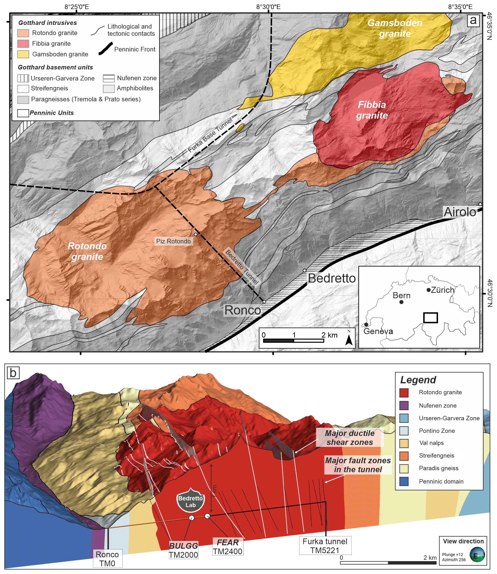
Figure 1(a) Schematic geological map showing the location of the Bedretto Tunnel in the Rotondo granite. (b) 3D geological cross section along the Bedretto Tunnel, highlighting the main geological features of the Rotondo granite.
Among the panorama of experimental approaches (boreholes, underground labs, and deep mines) aimed at observing earthquake sources, the Bedretto Underground Laboratory for Geosciences and Geoenergies (BULGG) in the Swiss Alps offers an ideal environment for the Fault Activation and Earthquake Rupture (FEAR) project. Located in a 5211 m long tunnel, BULGG provides easy access to a large volume of crystalline faulted rocks at depths of 1000–1500 m (Fig. 1; Ma et al., 2022). The FEAR project aims to re-activate a natural fault at this depth and observe the nucleation of a magnitude 1 event using advanced instruments. As detailed in Meier et al. (2024), the project involves controlled 50–100 m scale fault stimulation experiments, stress pre-conditioning for real-time testing, data-driven forecasting, and integrating results from various experimental and observational approaches. For the experiment, a new 120 m long tunnel parallel to the target fault will be excavated, providing extensive instrumentation for close-range monitoring (Fig. 2). Conducted by ETH Zurich, INGV Rome, and RWTH Aachen University and funded by a European Research Council (ERC) Synergy grant, FEAR integrates fault mechanics, seismology, and numerical modeling for scales ranging from laboratory to natural earthquakes (Meier et al., 2024). The project's success depends on selecting a fault with specific characteristics: a favorable geometrical orientation, continuity for hundreds of meters, limited water inflows, homogeneity and isotropy of the host rock, and evidence of past seismogenic activity. The ultimate goal is to stimulate and monitor the fault zone's slip episodes, strain perturbations, stress changes, seismicity, and pressure evolution at significant seismogenic depths (Meier et al., 2024). A novel aspect of the experiment is the unique opportunity to thoroughly characterize a fault in extreme detail before the project begins. This in-depth knowledge of the fault's characteristics will inform crucial decisions on how to instrument the fault, which parameters to observe with optimal instruments, and how to design the instrumentation architecture. One of the novelties of the experiment is the unique opportunity to target a fault that can be characterized in extreme detail before the project starts. The deep knowledge of the fault characteristics will drive important decisions on how to instrument the fault, which parameter to observe, and the optimal instruments to perform the observations, thus defining the architecture of the instrumentation assets. It will also be a unique opportunity to correlate direct observations (e.g., the structure of the rock, fracture systems, the distribution of gouge, and asperities) with geophysical observations (e.g., the seismic anisotropy at various scales, the localization of the seismic events, and their propagation in the time domain in correlation with the pressure distribution propagation) in great detail.
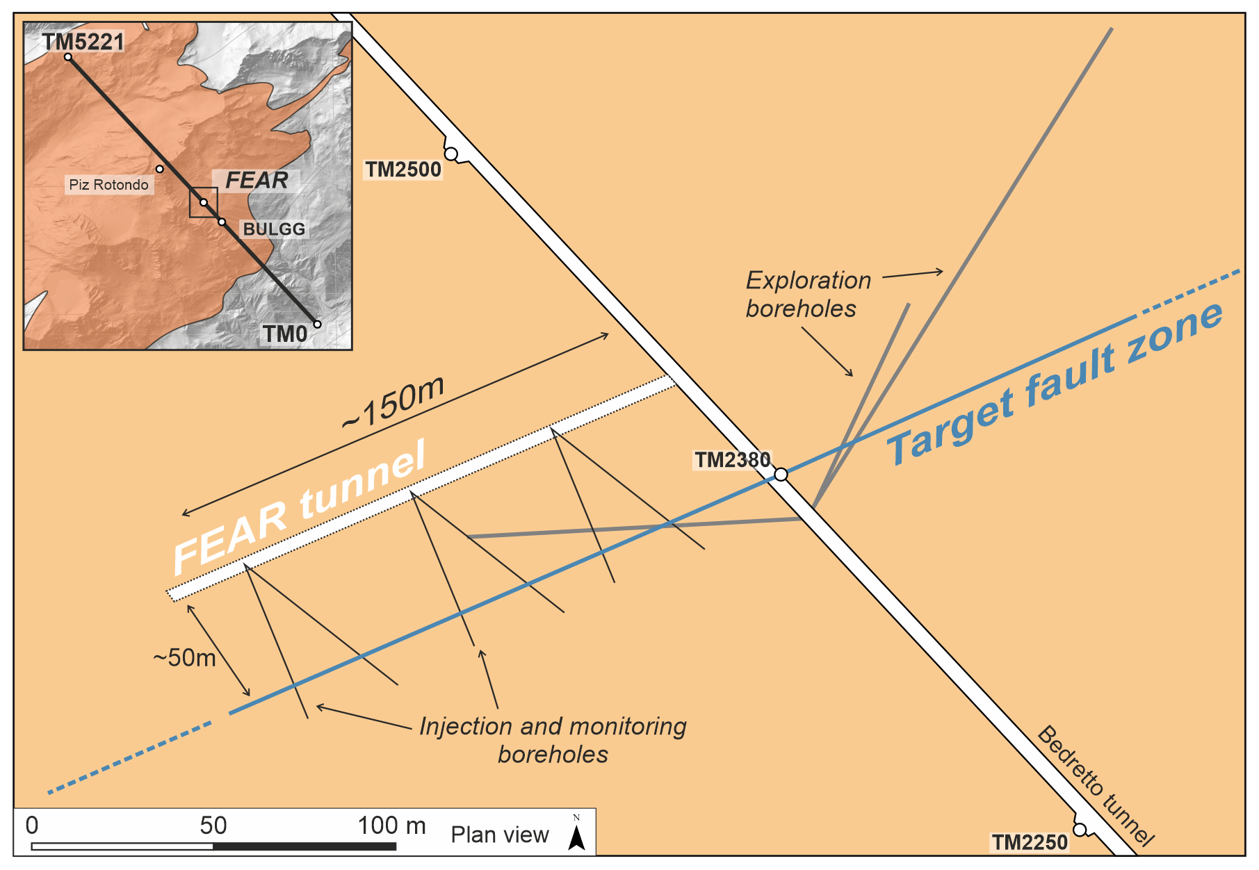
Figure 2Schematic plan view of the experimental setup of the FEAR project, highlighting the Bedretto Tunnel, the planned fault-parallel access tunnel (FEAR tunnel), the steeply dipping target fault zone (blue; termed the MC fault zone), and the planned boreholes that will host the monitoring instrumentation and the injection system.
This paper aims to present and discuss the multidisciplinary approach used to identify the target fault zone (the MC fault zone) for the FEAR experiments. We first summarize the information on the selected site, the Bedretto Tunnel, and then outline the constraints and criteria based on the experimental requirements for selecting the target fault zone. We describe the data and parameters analyzed in the site investigation program and present the observations and their interpretation that were used to determine the architecture, geometry, and key properties of the selected fault zone.
2.1 The Bedretto Tunnel and the Bedretto Underground Laboratory for Geoenergies and Georesources
The Bedretto Tunnel is located near the Gotthard Pass in the Swiss Central Alps. The Bedretto Tunnel is oriented N43° W, with a slope of 0.002–0.017 towards Ronco Portal, and it connects the Bedretto Valley (Ronco Portal is Tunnel Meter 0 or “TM0”) with the Furka Base Tunnel (TM5221) owned by the Matterhorn Gotthard Railway line (Fig. 1a). A detailed description of the tunnel is available in Ma et al. (2022). The 5221 m long tunnel runs entirely through crystalline rocks of the Helvetic domain and is generally unsupported, allowing continuous and direct access to the rock walls. For about 4 km, it crosscuts the almost undeformed Rotondo granite (Fig. 1, (Hafner et al., 1975; Rast et al., 2022). Since its construction between 1971 and 1982, the tunnel has been surveyed for relevant geotechnical structures by Hafner et al. (1975) and Lützenkirchen and Loew (2011).
2.2 Geology
The Rotondo granite is one of the major Post-Variscan granite intrusions characterizing the Gotthard massif (Berger et al., 2017). The host rock consists of polymetamorphic paragneisses, migmatites, and amphibolites of the Tremola and Prato series (Berger et al., 2017; Rast et al., 2022). The Rotondo intrusion is mainly composed of two granitic bodies of Early Permian age (295 Ma; Rast et al., 2022): a younger equigranular Rotondo granite (RG1) intrudes an older porphyritic Rotondo granite (RG2). RG2 is only observed in the tunnel, where it crops out between TM2805 and TM3437. After the emplacement of the Rotondo granite, the Gotthard massif underwent extensional tectonics related to the incipient opening of the Paleo-Tethys Ocean in Permian to Jurassic times (Guillot and Ménot, 2009). During the Eocene to Miocene, the Gotthard massif was involved in the Alpine orogeny (Rast et al., 2022; Herwegh et al., 2017, 2020). During the Alpine convergence and subduction, the Gotthard massif reached peak metamorphic conditions of higher than 550 °C and 0.9 GPa at 20–30 Ma (Ceccato et al., 2024). The following Alpine continental collision led to fast exhumation of the Gotthard massif at 18–19 Ma (Ceccato et al., 2024). During this tectonic phase, the main set of NE–SW-trending and ENE–WSW-trending ductile shear zones formed in the Rotondo granite at 520 °C and 0.8 GPa. This set of ductile shear zones localized at a pre-existing set of brittle faults and shear fractures (Ceccato et al., 2024). The following ductile-to-brittle evolution of the massif during exhumation and cooling was dominated by strike-slip tectonics, leading to the development of mainly dextral ductile-to-brittle shear zones and major brittle fault zones from 12 to 5 Ma (Kralik et al., 1992; Pleuger et al., 2012). These late stages of strike-slip tectonics at upper-crustal conditions (T<200 °C, depth < 7 km) led to the development of zeolite- and gouge-bearing fault zones that localized on pre-existing ductile shear zones and shear fractures (Lützenkirchen and Loew, 2011). Tectonic structures, such as ductile shear zones and faults, especially those in the host paragneisses, were exploited during the Neogene as nucleation sites for toppling zones and deep-seated gravitational slope movements (Fig. 1b; Ustaszewski et al., 2008).
This complex geological history has resulted in a variety of ductile, ductile-to-brittle, and brittle discontinuities. Therefore, criteria must be established to identify a suitable “target” fault zone to effectively use resources and maximize outcomes. The primary objective of the FEAR project is to induce seismic activity (with a maximum magnitude Mw=1.0) through hydraulic stimulation within a natural fault zone equipped with a multidisciplinary monitoring network offering unprecedented spatial resolution and proximity to the source. As part of the preparatory work, we are excavating a 120 m long access tunnel parallel to but 50 m from the fault zone. This tunnel will be used to install a dense, remotely controlled monitoring system on and off the target fault, allowing us to monitor the fluid pressure, strain, temperature, and seismic signals. The goal is to induce fault movement in areas with the most comprehensive monitoring. Various fluid injection and production strategies will be tested in borehole sections to (re)activate different fault segments and assess their responses to fluid stimulation.
Therefore, the selection criteria for the fault zone took into account the following components: (1) the geometry and spatial extent of the natural fault zone; (2) the logistics, the installation, the cost, efficiency, and density ratios of the equipment and the deployment of the monitoring system, and the sensitivity of the monitoring equipment; (3) hydro-mechanical characteristics; and (4) geological properties of the fault zone.
(1) Geometrical and spatial requirements
The ideal outcome of the FEAR experiments is to induce dynamic ruptures with moment magnitudes on the order of Mw=1.0. Assuming typical stress drops of 3 MPa and a shear rigidity of 30 MPa, this would correspond to ruptures with equivalent circular rupture area radii of ∼18 m and with an average slip of ∼1 mm (Kanamori and Anderson, 1975). Such ruptures would be large enough for us to potentially resolve the spatio-temporal evolution of coseismic slip. In order to activate different sections of the same fault zone in a suite of experiments, the ideal fault zone candidate would have a spatial extent on the order of at least 50 m by 100 m.
In addition, the structure should be favorably oriented with respect to the in situ stress field, with a high slip tendency (Morris et al., 1996) close to the static frictional resistance of the slipping zone (i.e., the conditions for which a fault is critically stressed). Minimal variation in terms of geometry and thickness would be required to minimize the complexity of the logistics, monitoring, and experimental and analytical operations. Therefore, planar continuous structures with minor variations in orientation and extent are the most favorable because they are more predictable (in terms of spatial development). Allowing for the four experiments planned (Meier et al., 2024), the fault zone needs a minimum lateral extent of 200 m.
(2) Monitoring requirements
A dense monitoring network of sophisticated and accurate monitoring sensors (cementable tube pore pressure sensors, fiber-optic cable for strain and temperature monitoring, borehole stress probes, acoustic-emission sensors, high-frequency accelerometers, etc.) will be deployed to provide high-resolution data within a (limited) volume around the fault zone. From the 120 m long fault-parallel access tunnel, we can instrument a fault zone segment of about 100×40 m with manageable cost and effort. Because the stressing of the fault patches will be monitored and predicted in real time, the maximal thickness of the structure that can be instrumented and reliably monitored is limited to 1–10 m. The lower boundary results from empirical correlations of spatial dimensions of architectural elements of fault zones, as derived by Kolyukhin and Torabi (2012), and from the consideration that the mostly ductile precursor of the fault zones in the Rotondo granite results in smaller damage zones Lützenkirchen (2002). The upper boundary is defined by the technical constraints of the planned monitoring network. The requirement assures that several main shocks Mw=1.0 in size are likely to be induced, monitored, and studied over the course of the project.
(3) Hydraulic requirements
The hydraulic characteristics of the fault zone play a crucial role in enabling the pressurization needed to induce slip during the hydraulic-stimulation experiments. Thus, the primary focus are the hydraulic properties, such as the hydraulic conductivity (or permeability), hydraulic connectivity, and in situ fluid pressure within the fault zone and in the surrounding rock mass. Fluid permeabilities should be high enough to allow the pressurization of fault segments of a significant extent. At the same time, we avoid fault zones with very high fluid permeabilities, since the pressure may rapidly dissipate in such structures, and we may not reach the pressures necessary to activate the fault.
As direct measurements of permeability are unavailable for the entire tunnel and are also not practical to conduct, a proxy, tunnel inflow category, was used to estimate the permeability of fault zones (similar to Lützenkirchen, 2002; Masset and Loew, 2010; Achtziger-Zupančič et al., 2017). Therefore, fault zones that were wet or dripping or those that displayed some minor flow to the current Bedretto Tunnel were considered suitable, while those with no flow or highly productive structures were unsuitable.
(4) Geological requirements
Homogeneity of the host rock is a fundamental requirement to receive optimal inversions of the seismic and hydraulic signals resulting from the experiments. Anisotropic host rocks, such as metamorphic rocks and ductile shear zones characterized by pervasive planar foliations, introduce a mechanical anisotropy into the system, which affects the complexity of the monitoring, analytical, experimental, and modeling operations. Additionally, geological characteristics of the faults that suggest past seismic activity in geological or recent times, as well as geological characteristics favoring the nucleation and propagation of seismic rupture during fault (re)activation, are preferred for the fault zone. In particular, the presence of granular and gouge (velocity-weakening) fault rocks (e.g., Niemeijer and Spiers, 2007; Volpe et al., 2023) was considered a favorable characteristic to induce seismic fault reactivation. In addition, fault intersections were also considered in the selection. Faults offset by other discontinuities have more complex fault zone geometries, altering stresses and hydraulics locally, and so they have different slip tendencies; thus, fault zones offset by younger fault sets were given lower priority.
Following the constraints defined above, a multidisciplinary and multi-scale approach has been developed to evaluate the hundreds of faults that crop out in the Bedretto Tunnel, in an effort to find the structure that best matches the criteria for the FEAR experiments. Integrated data were collected from regional to sample scale, both at the surface and in the tunnel. Methods included
-
the geological characterization at the field and tunnel scale in order to illuminate the geological characteristics of the faults in the Rotondo granite, their geometrical properties, and their spatial extents;
-
borehole drilling, logging, and core analyses;
-
geophysical investigations with ground-penetrating radar (GPR);
-
laboratory and sample characterization;
-
hydro-mechanical characterization.
The methods were applied in a three-stage process: (A) a general inventory of structures in the Rotondo granite; (B) narrowing of the tunnel section and the selection of the most suitable fault zone(s) based on the selection criteria; and (C) the characterization of the fault zone(s).
(A) Structural inventory
The general existence of suitable structures has been analyzed by remote sensing and field investigations, including
(B) Fault zone selection
To find and select the most suitable fault zones within the selected tunnel section, a prioritization process has been applied, which was based on
-
constraining the tunnel sections according to general geological, logistic, and operational considerations and ongoing operations in the BULGG (Sect. 5.2);
-
slip tendency analysis based on the poles of faults (Sect. 5.2; Ma et al., 2022);
-
GPR investigations along the tunnel wall (Sect. 5.2, Fig. 5).
The criteria-oriented investigations reduced the number of suitable fault zones to a few candidates.
(C) Fault zone characterization
The selected fault zone(s) have been characterized by following an integrated analytical and methodological workflow, including
-
detailed geological and structural characterization in the tunnel (Sect. 5.3; Fig. 7);
-
laboratory characterization of the mineralogy and microstructure of fault rocks, including experimental deformation to constrain the frictional, mechanical, and permeability properties of the fault rocks in the selected fault zone (Sect. 5.3; Volpe et al., 2023; Osten et al., 2024);
-
the drilling of exploration boreholes at an angle to the selected fault zone to constrain the actual lateral extent and continuity (Sect. 5.4; Fig. 6);
-
the logging of cores retrieved from boreholes (Sect. 5.4; Fig. 8);
-
borehole logging utilizing acoustic and optical televiewers (ATV and OTV) (Sect. 5.4; Fig. 8);
-
GPR logging (Sect. 5.4; Fig. 9).
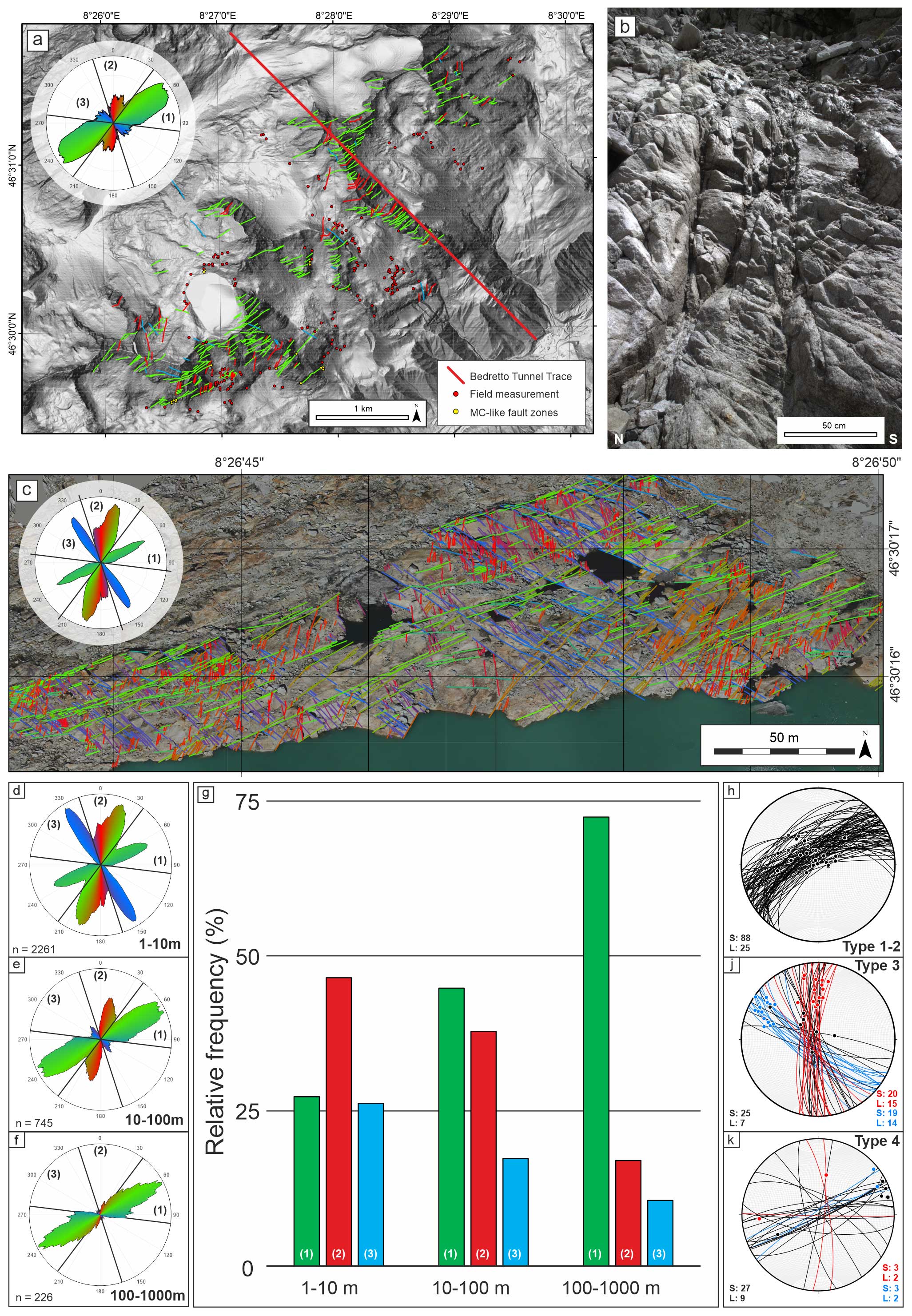
Figure 3Summary figure presenting the preliminary results from the remote-sensing data and the field survey in the Rotondo granite area. (a) digital terrain model (DTM) of the Rotondo granite area showing the trace of the Bedretto Tunnel relative to the investigated points on the surface (red dots). Field occurrences of MC-like fault zones are represented by yellow dots. The lineaments interpreted from remote sensing are color coded according to their strike (hillshaded digital elevation model (DEM) from SwissALTI3D). (b) Field example of MC-like fault zones represented by a narrow fracture corridor with multiple principal slip planes. (c) Interpreted outcrop map with the traced lineament. Orthoimages were obtained from drone surveys. (d–f) Rose diagrams obtained from the analyses of the lineament length data obtained from remote sensing, showing the distribution of lineament strike for each length class: (d) 1–10 m; (e) 11–100 m; (f) 101–1000 m. (g) Histogram showing the relative frequencies of the lineament sets (1–3) identified by remote sensing at each resolution scale. (h–k) Equal-area lower-hemisphere stereographic projections of the structural inventory from field analyses. Great circles: slip planes (S); dots and contour: lineations (L). Blue and red planes and dots represent dextral and sinistral kinematics, respectively. Data from Ceccato et al. (2024). (h) Type 1–2 ductile shear zones. (j) Type 3 brittle–ductile faults. (k) Type 4 zeolite- and gouge-bearing brittle fault zones.
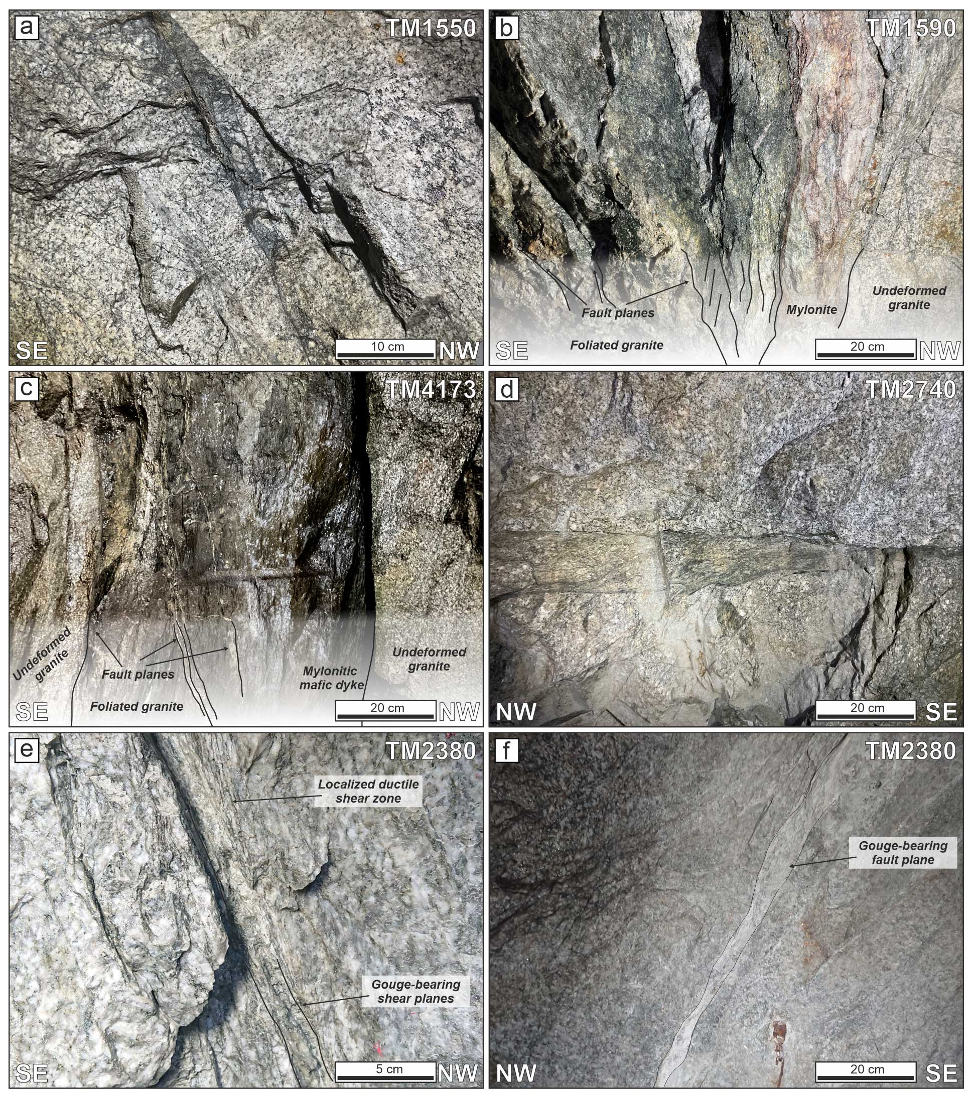
Figure 4Types of deformation zones observed in the Bedretto Tunnel. (a) Brittle breccia formed during pre-Alpine formation (D1 brittle cataclasite as described in Ceccato et al., 2024. (b, c) Type 1 ductile shear zone localized on pre-existing compositional and structural discontinuities. Note the occurrence of late-stage type 4 fault planes. (d) Type 2 brittle–ductile faults. (e, f) Type 4 zeolite- and gouge-bearing brittle faults. These pictures represent the fault planes at the MC fault zone outcrop.
The final result is a preliminary geological–geometrical model of the fault zone (Sect. 5.5; Fig. 10) integrating all the multi-scale observations resulting from multidisciplinary characterization. The proposed preliminary geometrical model is tested against synthetic GPR profiles computed with forward modeling as explained below (Sect. 5.6; Fig. 11). The detailed analytical techniques and methodological approaches adopted for fault zone selection and characterization are described in the following sections.
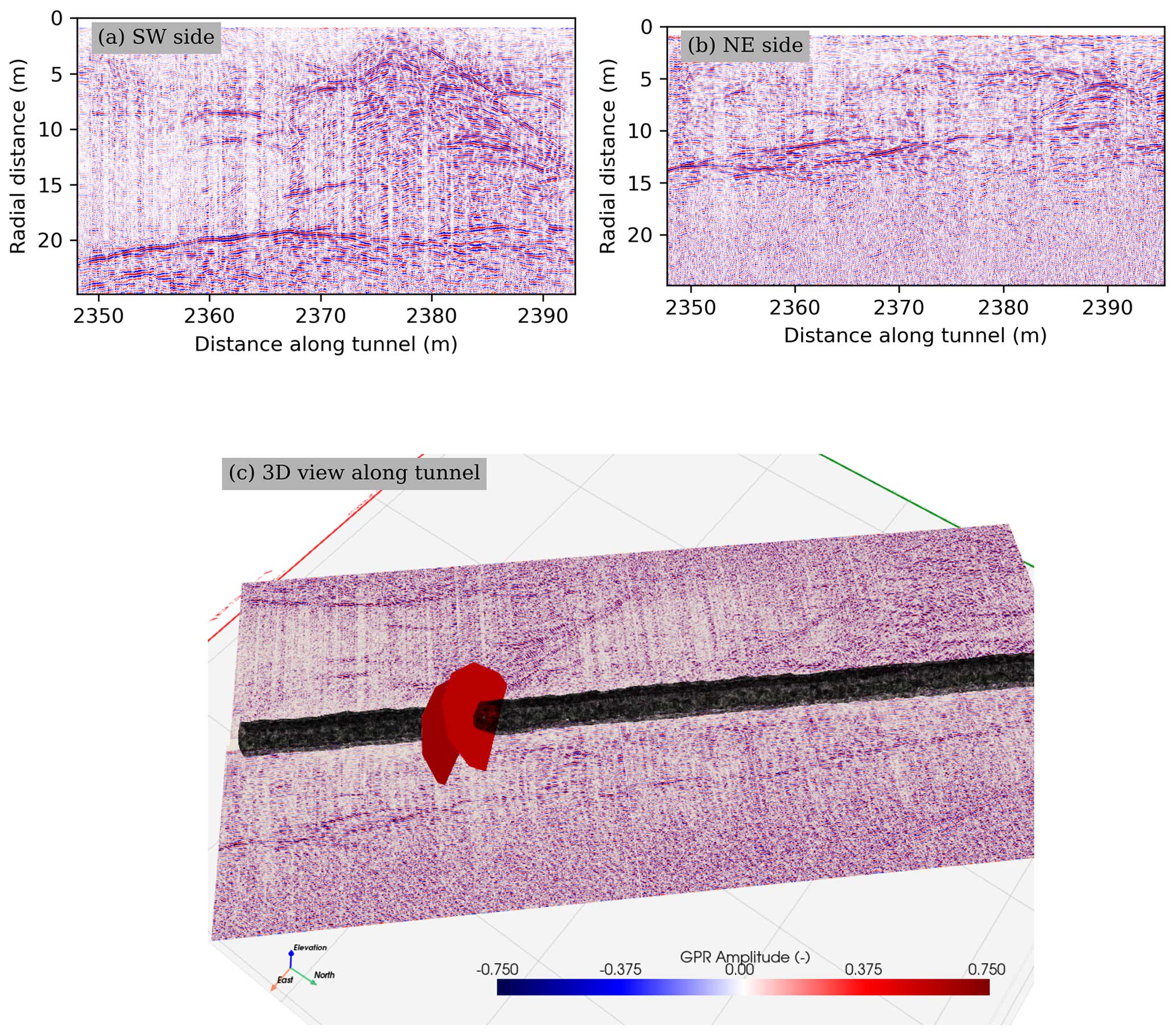
Figure 5Directional GPR scans along the (a) SW side of the Bedretto Tunnel around the MC fault zone (FZ) (TM2345–TM2395) and (b) NE side of the Bedretto Tunnel around the MC fault zone (TM2345–TM2395). (c) Oriented 3D view of the GPR sections with the orientation of the MC fault zone.
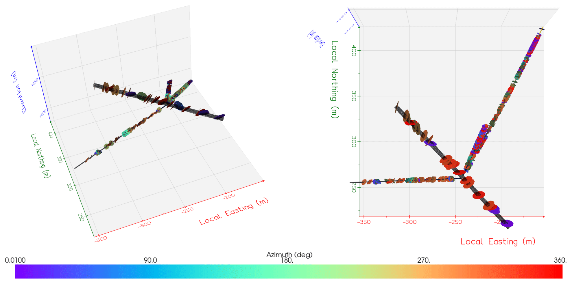
Figure 6Structures (both faults and fractures) observed along the tunnel and boreholes in the vicinity of the FEAR experimental volume, with an extent of roughly 250 m3. To highlight their orientation, the structures are colored according to their azimuths.
4.1 Remote sensing and geological field investigations in the Rotondo granite
Large-scale remote sensing and geological field surveys were used to document the structural elements of the Rotondo massif exposed at the surface above the Bedretto Tunnel. Remote-sensing analyses involved the manual interpretation of lineaments and structural features identified in multidirectional hillshade models computed from high-resolution DEMs (25 cm px−1, SwissSURFACE3D, Swisstopo), high-resolution aerial images draped onto the 3D DEM (10 cm px−1, SwissIMAGE database, Swisstopo), and orthophotos and a DEM of limited outcrops (200–400 m2) obtained through local surveys with uncrewed aerial vehicle (UAV) drones (0.5 cm px−1, DJI Mavic 2). The interpretation of lineaments was manually performed in ArcGIS on a hillshaded DEM and aerial orthoimages. The result is a database containing the orientation (dip, strike, and dip direction) and projected length of each element, which has been analyzed following the approach of Ceccato et al. (2022). Lineament strike was plotted in a moving-average rose diagram (Munro and Blenkinsop, 2012) to constrain sets with dominant orientations and the variation in relative frequencies from regional to local scale.
The field investigations focused on identifying the different deformation structures in the Rotondo granite and validating the remote-sensing interpretations. The structural characterization included the systematic collection of oriented and georeferenced data on planar (dip/dip direction) and linear (plunge/trend) features. The kinematics of deformation structures, the thicknesses of deformation zones, the mineralogy and fabrics of relevant shear zones (mineral composition, foliations, etc.), and the crosscutting relationship between characteristic sets of deformation structures were documented. The results of the field investigations have been compiled as a georeferenced database in Ceccato et al. (2024), focusing in particular on the identification and characterization of secondary geological features, such as hydrothermal alteration of the Rotondo granite related to deformation structures, that likely affect its petrophysical and geomechanical properties.
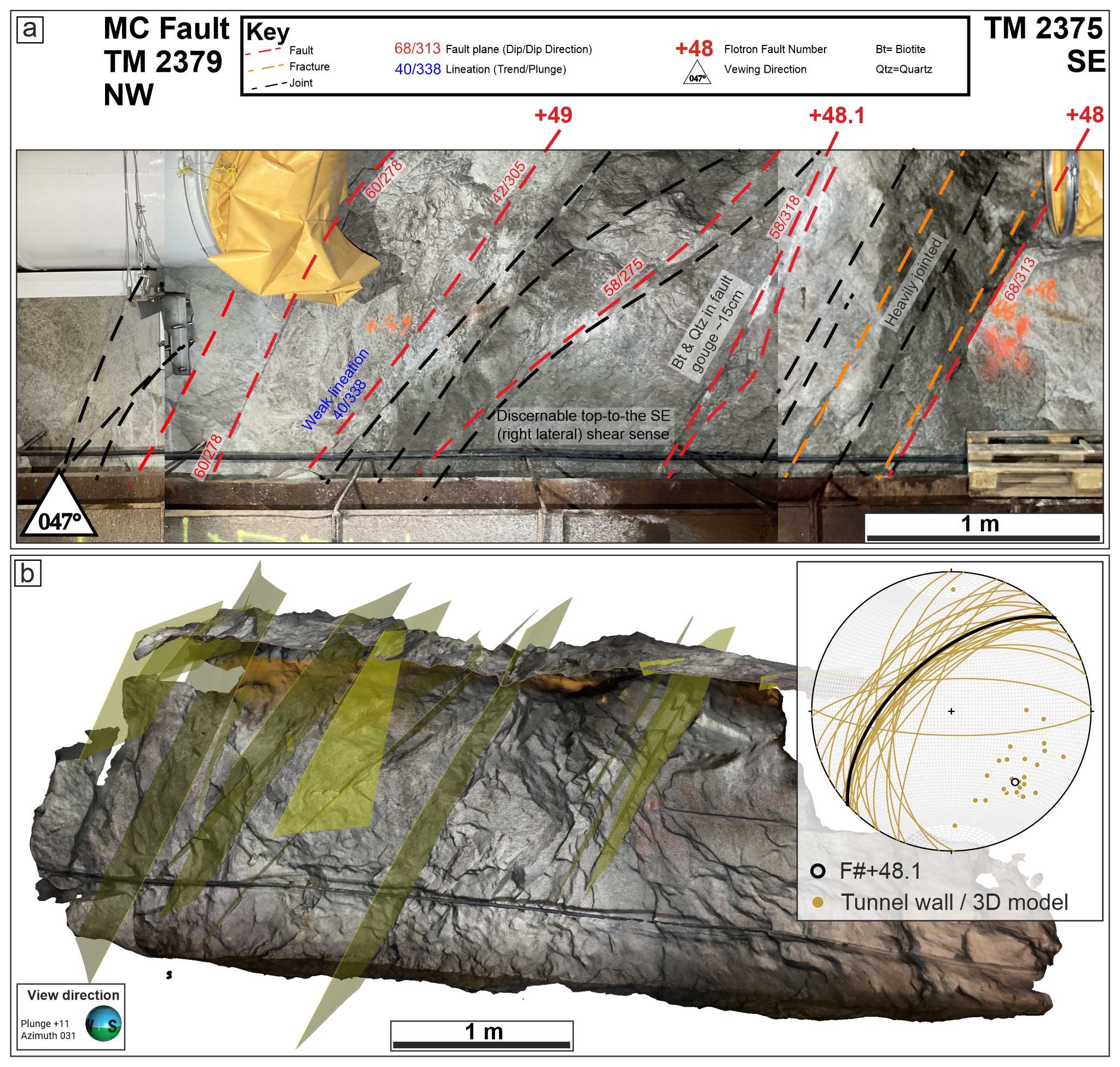
Figure 7The MC fault zone in the tunnel, rock cores, and boreholes. (a) Structural interpretation of the exposure of the MC fault zone along the NE wall of the Bedretto Tunnel at TM2380. (b) 3D model of the NE tunnel wall around the MC fault zone at TM2380. The transparent yellow planes represent the fracture planes interpolated from manual fitting in Leapfrog GEO. The stereoplot in the upper-right inset reports the orientation (great circles and poles to planes) of the observed and modeled fracture planes, including F#+48.1 on the tunnel wall and the orientation of the fractures inferred from analysis of the 3D model of the tunnel wall.
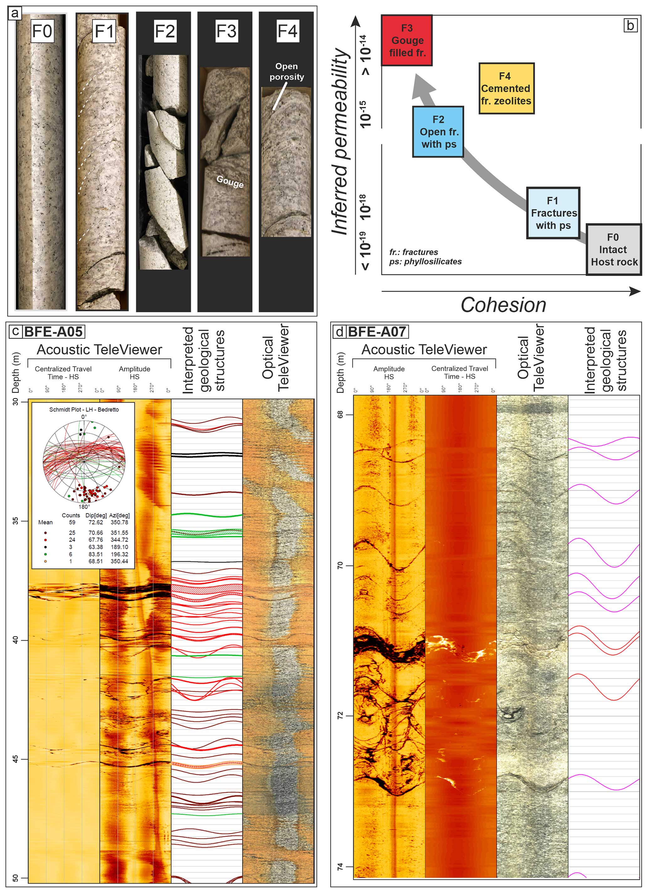
Figure 8(a) Examples of segments of rock cores extracted from the FEAR boreholes (BFE) representing the different core facies. (b) Qualitative diagram describing the relationship between core facies numbering, cohesion level of the rock core, and inferred permeability. (c, d) Example of the integrated logging of a borehole (BFE_A05, 30 to 50 m depth; BFE_A07, 68 to 74 m depth) from ATV and OTV, with the associated orientations of the interpreted geological structures plotted in the inset stereoplot.
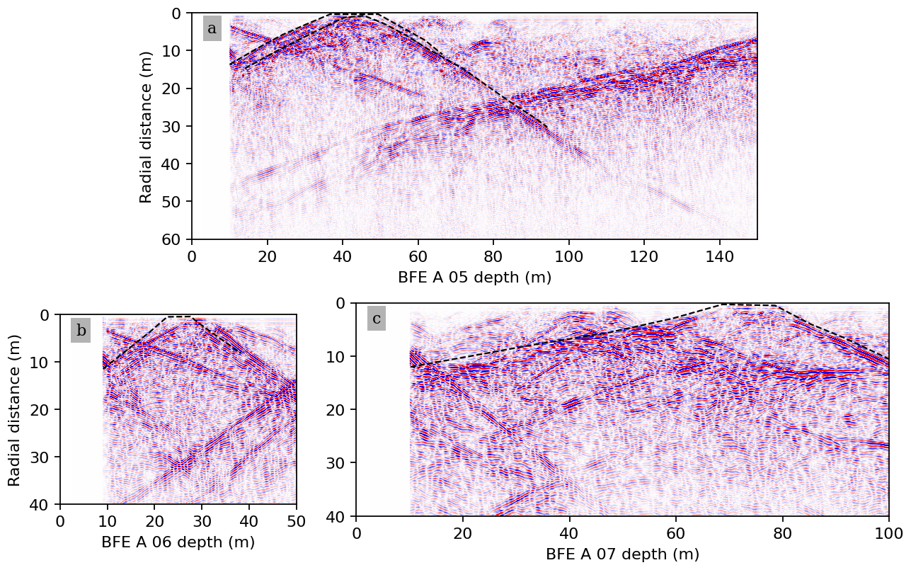
Figure 9GPR profiles along the exploration boreholes (a) BFE_A_05, (b) BFE_A_06, and (c) BFE_A_07, with the trace of the MC FZ indicated in each profile.
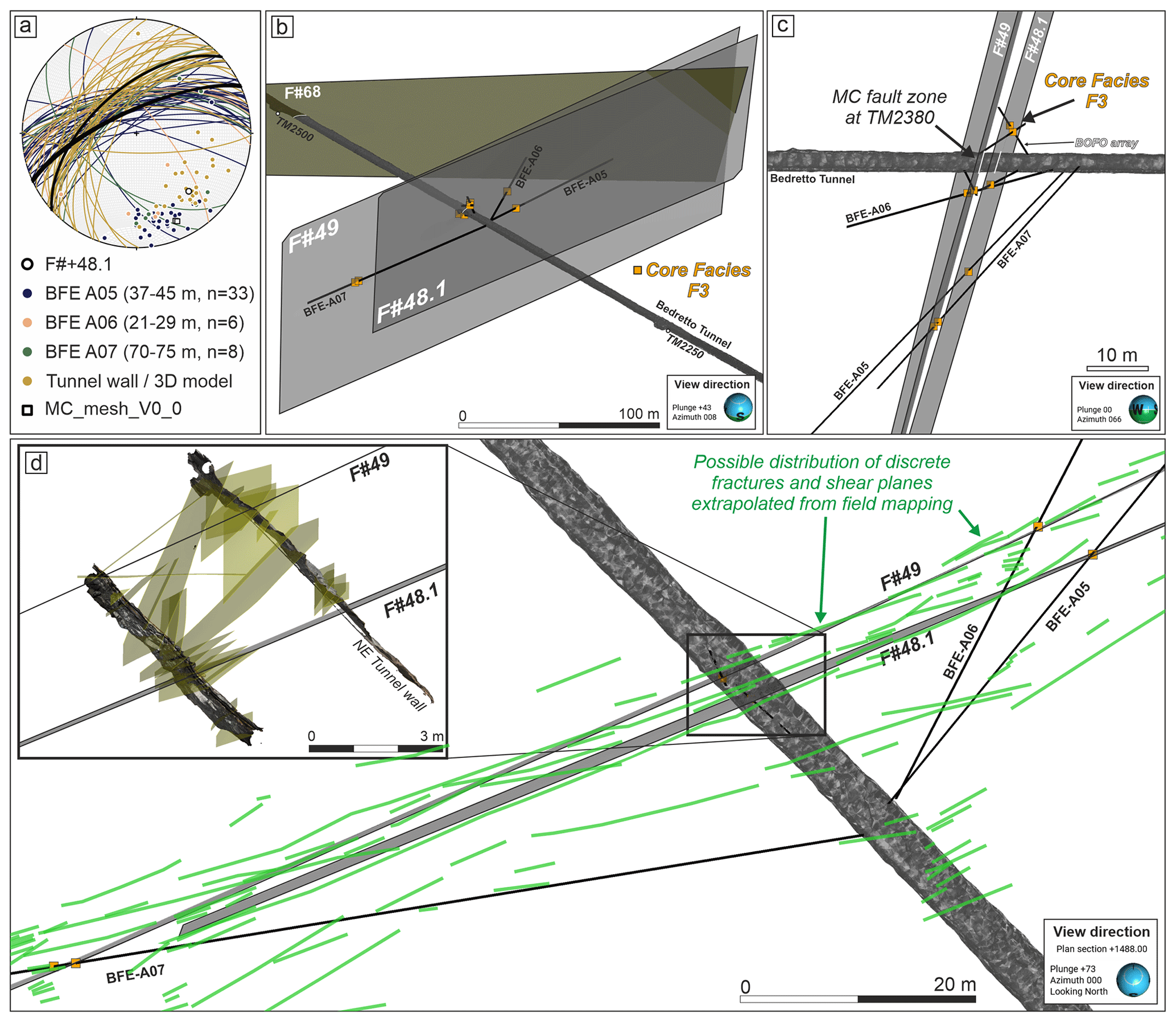
Figure 103D geometrical model of the MC fault zone from tunnel observations, the core facies distribution, and borehole logging. (a) 3D model of the NE tunnel wall around the MC fault zone at TM2380. The transparent yellow planes represent the fracture planes interpolated from manual fitting in Leapfrog GEO. The stereoplot in the upper-right inset reports the orientations (great circles and poles to planes) of the observed and modeled fracture planes, including F#+48.1 on the tunnel wall and the orientation of the fractures in BFE boreholes as inferred from OTV and ATV logging; The orientations of the fractures were inferred from analysis of the 3D model of the tunnel wall; the orientation of the two main meshes (MC_mesh_V0_0) was defined through the interpolation of tunnel, core, and borehole data. (b) Overview of the 3D model of the MC fault zone, which was composed of two main surfaces (meshes F#+49 and F#+48.1 bounding a zone of high fracture intensity. (c) Side view of the 3D model showing the distribution of the borehole arrays and the location of the F3 facies in each borehole. (d) Plan view of the MC fault zone showing the two main surfaces interpolated from the core facies distribution. The light green traces represent the likely heterogeneous distribution of discrete fractures and shear planes as inferred from field mapping of structures similar to the MC fault (Fig. 3c). The inset shows the fractures interpreted from lidar scanning and structural analysis of the tunnel wall. Note the slight difference in orientation between the tunnel wall fractures and the interpolated surfaces.
4.2 Drilling, geophysical, and core investigations
To assess the lateral continuity, planarity, and thickness of fault zones in the tunnel, a ground-penetrating radar (GPR) measurement campaign has been conducted along the tunnel walls and inside the exploration boreholes BFE_A_05, _06, and _07. Both GPR systems consist of a transmitter and receiver antenna pair (developed by MALÅ, GuidelineGeo AB), which emits and records electromagnetic signals in the megahertz (MHz) range. A 160 MHz system has been used for the acquisition at the tunnel walls, and a 20 MHz and 100 MHz system has been used in the borehole campaigns. The successful imaging of faults at distances of up to 60 m into the rock volume due to the strong dielectric contrast between the intact Rotondo granite and water-bearing or gouge-filled structures was previously demonstrated at BULGG (Shakas et al., 2020). Since the conditions and environment are identical to those considered in Shakas et al. (2020), we do not elaborate here on the processing steps applied to raw data; we show structurally interpreted results instead.
Potential candidate fault zones have been mapped in detail by the scanline approach along the tunnel. Three sub-horizontal (approx. 10–20° downdip) exploration boreholes were drilled to depths of ≃216 m (BFE_A_05, NE side), ≃55 m (BFE_A_06, NE side), and ≃101 m (BFE_A_07, SW side). The boreholes were diamond drilled, and the resulting cores were integrally documented with digital images and cataloged using a local database compatible with the Mobile Drilling Information System adopted by ICDP projects (Harms, 2021). Cores allowed the mapping of structural discontinuities and the identification of a small number of core facies (Fig. 8a). Five main core facies have been delineated, ranging from F0 (intact host Rotondo granite) to F4 (altered and faulted granite).
As the core facies identifier increases from F0 to F4, the degree of fracturing, the occurrence of open fractures or gouge-filled fractures, and the presence of hydrothermal alteration in the host granite increase (Fig. 8b). The core facies numbering also qualitatively reflects the primary, secondary (fracture), and tertiary (dissolution) porosity and cohesion characteristics of the rock, which – based on experience from previous boreholes – correlate with its permeability. The facies were correlated between the boreholes to trace the lateral continuity of structural and lithological features.
Aside from core logging, wireline logging measurements have been conducted inside these boreholes. In addition to GPR (as described above), optical and acoustic televiewers (ATV and OTV) from Advanced Logic Technology (ALT) have been deployed. The wireline logging allows (a) accurate measurements to be obtained for the orientation of the borehole, in terms of its tilt and azimuth, along its entire depth and (b) both the orientations and the types of structures that intersect the borehole to be characterized. The combination of cores, televiewer imaging, and borehole GPR provides a comprehensive dataset to correlate the candidate structures in the tunnel with those in the boreholes. In Fig. 6, the geometries of the three exploration boreholes drilled from the Bedretto Tunnel are shown.
4.3 Petrological, petrophysical, and hydro-mechanical investigations
Lab investigations consisted of the analysis of the rock mineralogy, rock fabric, frictional properties of fault gouges (the cataclastic product of the high-strain fault cores), water chemistry, porosity, density, permeability, and frictional properties. The physicochemical properties of groundwater (temperature, pH, and electrical conductivity) have been characterized based on regularly acquired samples from torrents, natural tunnel inflows, and borehole outflows (Arnet, 2022). Analyses include those of the water composition and isotopic ratios.
Rock samples from field and tunnel outcrops and from segments of borehole logs have been analyzed as thin sections and using optical microscopy. The fault gouge mineralogy has been assessed via X-ray powder diffraction using a Bruker D8 Advance X-ray system provided with a Lynxeye XE-T silicon-strip detector (Volpe et al., 2023). Additionally, rock deformation experiments have been conducted using the natural gouge sampled from the fault cores at TM2380 and TM2800 (Volpe et al., 2023). These experiments yielded information on the frictional properties and permeability of the sampled gouges, with implications for the fault slip behavior during reactivation. The permeability and porosity of rocks from fault zones were measured by helium pycnometry and water saturation methods, flow-through experiments under confined conditions, and unconfined gas permeameter measurements (Osten et al., 2024). These samples were collected at TM1590 (four boreholes of less than 1 m), TM2380 (four boreholes of less than 1 m), and TM2780 (three boreholes of 10 m). Lab investigations are briefly summarized here. The reader is referred to the published theses and referenced articles for further details.
4.4 Geological–geometrical data integration, geometrical modeling, and GPR simulations
The different datasets obtained from the regional-scale to borehole-scale characterization of the target fault have been integrated into a 3D model to constrain the geometrical characteristics and spatial persistence of the selected target fault zone. In particular, tunnel observations, lidar scanning and virtual outcrop models, the distribution of fracture intensity, and the core facies distributions in boreholes were integrated and adopted as input datasets to compute 3D geometrical models of the fault zone with two different approaches.
The first geometrical model of the selected fault zone was computed using the 3D geological modeling software Leapfrog GEO (Seequent, Bentley Systems Inc.). Leapfrog GEO is based on implicit modeling methods, with the FastRBFTM (radial basis functions) method used to interpolate large datasets of sparse points to create continuous meshes with variable geometry. To get a first constraint on the lateral extent and geometry of the selected fault zone(s), a 3D model has been established from tunnel observations and the core facies distributions in the cores.
This fault zone model has been used for forward GPR simulation, following the modeling approach of Shakas and Linde (2015), for comparison to the GPR measurements. To account for the slight curvature resulting from the interpolation, a novel meshing approach has been employed, which is introduced in Escallon et al. (2023).
5.1 Structural inventory above the Bedretto Tunnel
The results from remote sensing allowed us to identify three main sets of lineaments showing different orientations, spatial distributions, lateral persistences, and relative frequencies at the scales of observation (Fig. 3a). These lineament sets include (Fig. 3c–f)
-
Set (1) – NE–SW- to ENE–WSW-striking lineaments with a lateral persistence of up to several hundreds of meters that are organized into a hierarchical spatial distribution and are predominant in terms of frequency at the regional scale (lineament lengths: 100–1000 m);
-
Set (2) – N–S-trending lineaments, usually consisting of short segments, with limited lateral persistence;
-
Set (3) – WNW–ESE- to NW–SE-trending lineaments with limited lateral persistence and a scattered occurrence in the Rotondo granite.
The results from field analyses provided more information on the geological characteristics of the remotely sensed lineaments and allowed us to define a relative chronology between the lineament sets. The deformation sequence inferred from field analyses includes a complex series of brittle, ductile, and ductile-to-brittle shear zones that dissect the Rotondo granite. A detailed description of the deformation structures, the deformation sequence, and the related tectonic interpretation is provided in a separate paper (Ceccato et al., 2024). A brief summary of the main characteristics relevant to the FEAR project is given below. The sequence (from older to younger) includes three main types of structures (Fig. 3b and g–j):
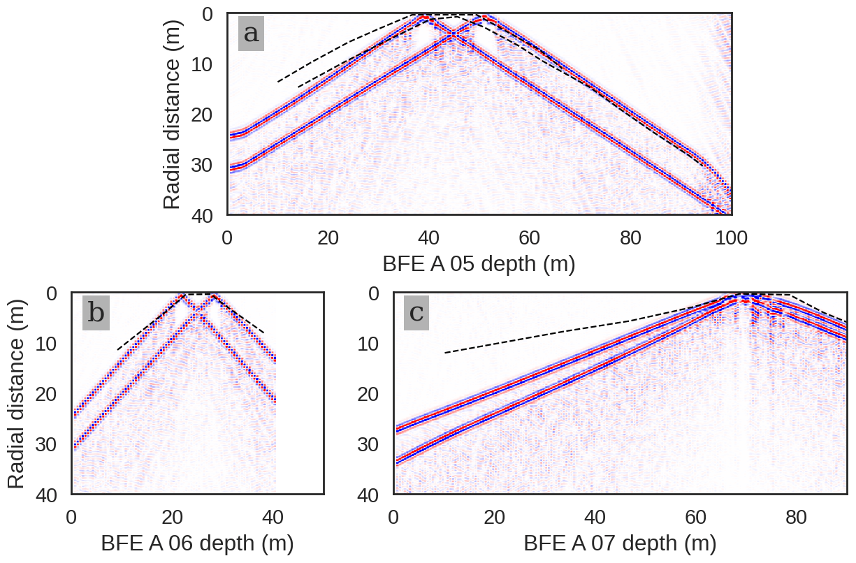
Figure 11GPR forward model obtained using the methodology from Shakas and Linde (2015) and the 3D geometry for the MC fault zone (planes 48 and 49). The simulation aimed to reproduce the results observed in borehole BFE_A_05. The dashed line superimposed on the image is the trace of the MC FZ picked from field observations (see Fig. 9).
-
Type 1 – NE–SW- to E–W-striking, steeply NW-dipping ductile shear zones with reverse kinematics (Fig. 3h). These shear zones are commonly superimposed on pre-existent magmatic features (mafic and aplitic dykes) and structural discontinuities (shear fractures, cataclasites, and breccias) related to the pre-Alpine tectonic evolution of the Rotondo granite (Fig. 4a). Type 1 structures exhibit a synkinematic mineral paragenesis suggesting amphibolite to upper-greenschist facies conditions. The thickness of these shear zones ranges from a few millimeters to several meters (Fig. 4b and c). These ductile shear zones are included in lineament Set (1) inferred from remote sensing.
-
Type 2 – strike-slip ductile shear zones, mainly ENE–WSW and E–W striking, that overprint pre-existing ductile shear zones with dominant dextral kinematics. Strike-slip shear zones are again included in Set (1) defined by remote sensing.
-
Type 3 – these structures are composed of two conjugate sets of steeply dipping, N–S- and WNW–ESE-trending brittle–ductile faults with transpressional kinematics inferred from the slightly oblique, shallowly N-plunging lineation (Fig. 3j). These structures define lineament Sets (2) and (3) identified by remote sensing. The transpressional faults are usually characterized by chlorite and quartz mineralization in dilational stepovers and tensional veins, suggesting formation at lower-greenschist facies conditions (e.g., Fig. 4d). In addition, some of these faults are related to a local hydrothermal alteration of the granite related to quartz leaching and the development of episyenites, i.e., spatially heterogeneous volumes of highly porous and permeable granite (Pennacchioni et al., 2016).
-
Type 4 – brittle fault zones and shear fractures typically defined by zeolite- and gouge-bearing shear surfaces. Their dominant strike is ENE–WSW trending, although the reactivation of other minor structures with different orientations is also observed (Fig. 3b and k). These faults mainly localize at the rheological, compositional and/or mechanical contact between undeformed host rock and major mylonitic shear zones (Fig. 4b, c–e, and f). Therefore, Type 4 structures are included in lineament Set (1) identified by remote sensing. Zeolite-bearing faults are commonly decorated by thin plane-parallel layers of whitish breccia made of host rock clasts in a zeolite-rich cement. Gouge-bearing faults are characterized by a phyllosilicate-rich gouge layer up to 10 cm in thickness.
Multi-scale remote-sensing analyses and field investigations of lineament sets and structure types provide fundamental constraints on the spatial organization and geometry, such as the lateral extent, of deformation zones. The geometry and spatial organization of Set (1) lineaments and Type 4 brittle fault zones are of particular relevance for the selection of the fault candidate. Set (1) lineaments are the most laterally continuous at the regional scale; they are composed of both ductile shear zones and localized faults reaching lengths of more than 600 m as continuous planes. The Type 4 brittle faults that define part of lineament Set (1) are organized into clusters and fault zones at the outcrop scale, with across-strike thicknesses of between 2 and 10 m and a lateral persistence of several hundreds of meters (green fractures in Fig. 3c). However, these clusters and fault zones are composed of discrete and discontinuous shear surfaces and fracture planes, each of which is usually less than 30 m in length (Fig. 3c). Additionally, Type 4 brittle fault zones exhibit zeolite-bearing shear planes, fault mirrors, and cataclasites. Indeed, such zeolite-bearing fault rocks are quite widespread in crystalline basement units of the Alps (Weisenberger and Bucher, 2010) and have been interpreted as having likely resulted from past seismic activity related to (hydrothermal) fluid injection (Dempsey et al., 2014; Ceccato and Pennacchioni, 2018).
5.2 Fault zone selection
In the process of selecting the candidate fault zones, the southern section of the Bedretto Tunnel from the entrance at Ronco to TM1100 was excluded. This section crosscuts the polymetamorphic sequences of the Tremola and Prato series (which are highly anisotropic lithologies where the overburden stress is oblique, making predictions of the stresses acting on the faults highly uncertain) leaving the Rotondo granite section of the Bedretto Tunnel. The section extending up TM1800 was also excluded due to the small rock overburden (<1000 m), resulting in insufficient stress magnitudes for the FEAR project. The estimated stress components in BULGG, based on mini-frac tests in boreholes at TM1750–TM2250, are MPa and MPa (Bröker and Ma, 2022). The average vertical stress Sv, calculated assuming an overburden of 1000–1100 m with a constant rock density of 2.62 g cm−3, is 26.5 MPa. The direction of SHmax is approximately N100E (Ma et al., 2022), albeit with some variations (Bröker et al., 2024). Thus, fault zones that exhibit steep to intermediate dips and strike orientations between NE–SW and NW–SE yield the highest slip tendencies (up to 0.4; Ma et al., 2022) and have been selected as the primary subjects of investigation. It is worth noting that the absolute values of slip tendency are lower than the empirical Byerlee's friction values (≥0.6) expected for granite, and possible stress variations near the fault zone have been observed (Zhang et al., 2023), which could modify the slip tendency significantly. According to He pycnometry and water saturation methods, drill core samples from fault zones yielded a density of around 2.6 g cm−3 and total and connected porosities of 1.9 %–2.8 % and 0.9 %–1.1 %, respectively (Osten et al., 2024). These properties varied little across fault zones.
Section TM1800–TM2000 was excluded as it comprises a highly dissected rock mass which is hydraulically connected to the neighboring section TM2000–TM2100, which is included in ongoing experiments run by other teams at the BULGG. The section TM2100–2350 consists of massive Rotondo granite and is devoid of relevant faults. Beyond TM3000, the granite has been deformed into ductile shear zones with a gneissic, anisotropic fabric and lacks evidence of fault reactivation; therefore, structures in this section are considered less favorable. The section between TM3200 and the connection to the Furka Tunnel was also excluded due to infrastructural and administrative restrictions associated with the borders of the cantons of Ticino, Wallis, and Uri. Hence, the research was restricted to the section TM2350–TM3000, which includes ca. 50 potential structures that could roughly correspond to the requirements for the fault reactivation experiments.
Structural mapping revealed a higher density of suitably oriented structures with different degrees of complexity in section TM2350–TM2550. Detailed scanline surveys (performed at the SW wall) indicate multiple overlapping fault zones clustered into four sets with dip/dip directions of (set 1), (set 2), (set 3), and (set 4). The first two sets can be grouped into a single set with an average orientation of . Fault zones oriented sub-parallel to the tunnel (striking NW–SE) were excluded due to the difficulty in resolving their positions and geometries and the risk posed to existing infrastructure in the case of reactivation.
GPR measurements conducted along the tunnel walls between TM2350 and TM3200 indicate clear reflectors as lines sub-parallel to the tunnel. This is a result of the acquisition geometry of the GPR system, which is primarily sensitive to reflectors along the direction of travel, as seen in Fig. 5. While the entire section has been scanned on both sides, it has been observed that the section from TM2750–TM3200 corresponds to a significant water-bearing, interconnected “reservoir”. This observation agrees with the consistent compositions and similar physicochemical properties of fluids measured across this section (Arnet, 2022). However, lower temperatures, a higher pH, and low mineralization have been measured in larger fault zones; these values partially resemble those of meteoric or glacial surface water (Arnet, 2022). Notably, the transition in water chemistry, GPR reflections, and anisotropic rock fabric corresponds to the change from equigranular Rotondo granite (RG1) to porphyritic Rotondo granite (RG2). Considering these results, we further restricted our assessment to the tunnel section around TM2350 to TM2750 for the selection of the candidate fault zone.
Roughly 5–7 MPa of water pressure has been measured in the exploration boreholes some 15 m from the tunnel wall, agreeing with previous measurements in boreholes around TM2050 about 100–200 m below the tunnel floor (Ma et al., 2022) and at the junction to the Furka Base Tunnel (Ofterdinger et al., 2014; Lützenkirchen and Loew, 2011). These head measurements indicate an almost horizontal head distribution in the overburden ranging from 800–1300 m across the mountain ridge. Thus, the rock mass is underpressurized, which is potentially a result of the long-lasting drainage of the tunnel. Permeability, as determined using (a) unconfined gas permeameter measurements of cores, (b) the flow through cells on confined core samples, and (c) hydraulic testing in various boreholes, varies in the range of to m2 within short distances. Fluid flow is strongly focused on single open or partially mineralized fractures with permeabilities in the range of to m2 (Osten et al., 2024). As observed from tunnel inflows and borehole flow logs, the main flow paths are along the bounding faults, which are partially well connected through the more fractured rock mass in between. Average protolith permeability ranges between 10−18 and 10−19 m2 (Osten et al., 2024).
5.3 Fault zone characterization
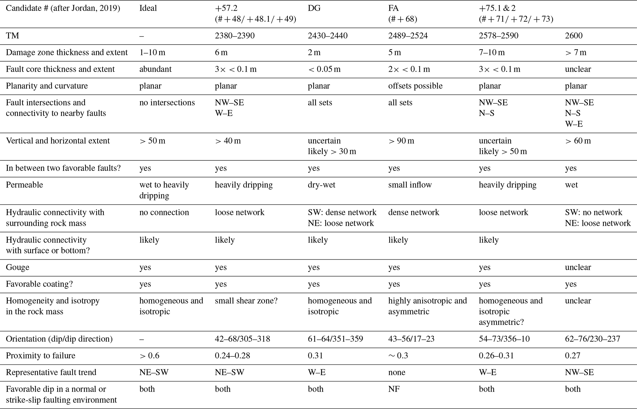
The constraints from analyses in the tunnel reduced the selection to a total of five candidate structures with a good fit to the ideal characteristics for the FEAR project (see Sect. 3). The relevant properties of the remaining five fault zones are briefly described in comparison to the ideal fault zone for the planned FEAR experiments in Table 1. As shown in the compilation, the fault zone at TM2380–TM2390 is slightly more suitable than the other structures. This structure is subsequently termed the MC fault zone.
The MC fault zone is located at TM2380–TM2390, and the GPR reflections on either side of the tunnel reveal that this fault should extend more than 15 m beyond the tunnel walls and into the rock volume (Fig. 5c). The reflections are more intense at the southeast wall of the tunnel (Fig. 5a).
The MC fault zone is located in a section of RG1 granite showing only a few, small, deformation structures. The MC fault zone belongs to the Type 4 structure set (Sect. 5.1), its overall orientation is , and the lateral persistence of this fault zone is likely to exceed 100 m, as inferred from the analysis of surface lineaments with a compatible orientation (Type (4)–Set (1) lineaments; Fig. 3). On the tunnel wall, the fault zone is composed of a set of shear fractures bounded by two discrete main shear planes (labeled F#+48 and F#+49 in Fig. 7) sandwiching a roughly 2–7 m wide zone of higher fracture density compared to the intact Rotondo granite. Roughly in the center, another main central shear plane was observed (labeled F#+48.1 in Fig. 7), which is decorated by a gouge layer.
Each main shear plane (F#+48, 48.1, 49) is localized on a pre-existing 5–10 cm thick ductile shear zone defined by a biotite-rich foliation and weak lineation (Fig. 4e and f). Overall, the lineations on the shear planes of the MC fault zone show a wide range of orientations, suggesting a long-lasting multi-mode history of movement dominated by reverse (compressive) to strike-slip shear senses, as inferred from meso-structural kinematic indicators showing a SE-ward shear movement of the hanging wall. The MC fault zone contains several other discrete fracture planes that differ in strike by 20–30° compared to the shear planes bounding the fault zone. The central main shear plane (labeled F#+48.1; Figs. 7a and 4f) is oriented . The fault rocks observed along the main shear plane are composed of a zeolite-rich cemented cataclasite to breccia (<50 mm; Fig. 4f) that features a thin (<10 mm) gouge layer with a patchy, discontinuous distribution on the shear plane. The gouge composition is very close to that of the host granite, with a slight enrichment in phyllosilicates, mainly muscovite and minor chlorite (for a detailed description and illustration, we refer the reader to Volpe et al., 2023). Laboratory shear experiments were performed on the gouge from the MC fault zone to simulate in situ stresses and fluid pressures (Volpe et al., 2023). The analyzed gouge is overall slightly velocity strengthening, but it was demonstrated that it still can slip seismically if the hydraulic pressure is sufficiently large (Volpe et al., 2023). Based on the laboratory experiments and the hydraulic and stress field observations, a scenario analysis of the slip tendency of the MC fault zone has been performed, which indicated that an overpressure in the range of 6 to 10 MPa is needed to reactivate the faults.
5.4 Borehole investigation of the target fault zone
To gain insights on the lateral continuity of the MC fault zone and its geometry, data from borehole logging, cores, and GPR imaging have been integrated into a 3D geological–geometrical model, as explained below.
5.4.1 Borehole logs, cores, and facies description
In order to identify the occurrence of the MC fault zone at depth along the boreholes, rock cores from BFE_A05, _A06, and _A07 were analyzed and classified into different core facies representing segments of the cores with similar geological characteristics. Comparing the core facies to the characteristics of the MC fault along the tunnel wall and defining the positions of the different core facies along the boreholes, we constrained the overall geometry and occurrence of the MC fault at depth.
The core facies adopted for the classification of the cores include (Fig. 8)
-
F0: intact rock with rare (≪5 m−1) thin and cohesive fractures filled with phyllosilicates;
-
F1: facies characterized by a dense set of oriented cohesive fractures filled with phyllosilicates and with mylonitic fabric;
-
F2: similar to F1, but the fractures are not cohesive – the granite is characterized by enhanced porosity and incipient (hydrothermal) alteration;
-
F3: severely damaged rocks with oriented fractures and the presence of cataclastic breccia or fine gouge (the gouge is usually accidentally removed during core extraction, but small patches persist on some fractures);
-
F4: cataclasites to heavily fractured granite cemented by zeolites with high matrix porosity (rare).
Each facies is characterized by different petrophysical (permeability) and mechanical (cohesion) properties, which are briefly summarized in Fig. 8b. The analysis allowed the position of the MC fault zone at depth along the boreholes to be defined. In particular, core facies F3 resembles the main plane F#+48.1, with a higher density of open fractures, the occurrence of loose gouge material, and minor hydrothermal alterations seen as porous granite. Accordingly, BFE_A05 and BFE_A06 intersect the MC fault zone at 37–45 m (Fig. 8c) and 22–27 m from the tunnel wall, respectively. BFE_A07 crosscuts only a thinner and less developed (minor brittle damage) part of the fault zone at 71–72 m (Fig. 8d).
OTV and ATV logs confirm the observations independently, adding orientation information for the fractures. Five clusters have been identified in the MC borehole sections resembling the MC fault zone: (strike 80°), (strike 80°), (strike 128°), (strike 147°), and (strike 30°) with consistently open fractures (Figs. 8d and 10a). The orientation of the fractures associated with the MC fault zone at the tunnel wall is more variable but consistent with the observations from the boreholes (Fig. 10a).
5.4.2 Single-hole GPR imaging
Single-hole GPR measurements were collected along each of the BFE boreholes (Fig. 9). The radargrams obtained with the 20 MHz antennas are presented and interpreted, and they show the MC fault zone clearly. The GPR reflections generated from the MC fault zone are evident in all three boreholes and reach more than 100 m laterally into the adjacent rock mass. The possible tunnel intersections of these reflectors are consistent with those of the main planar features measured in the tunnel. Nevertheless, the azimuthal ambiguity prevents the delineation of the exact origin of the reflections. Along the radargrams, the boundaries of the MC fault zone are delineated by V-shaped (chevron) patterns, which result from the intersection of faults and boreholes at a high angle (Olsson et al., 1992). The reflectors intersect the boreholes at the depths of the fault line suggested by the interpretation of the core and wireline logs. The rock mass between the two to three main reflectors appears as a high-contrast zone, suggesting the presence of a water-filled fracture network. GPR in BFE_A05 additionally shows that the MC fault zone crosses a ∼20 m wide, W–E-striking shear zone (called DG or FZ#+68).
5.5 3D geometrical model of the MC fault zone
The model of the MC fault zone (Fig. 10a–c) resulting from the field investigation consists of two main bounding faults. These two planes crosscut the tunnel at the approximate location of F#49 and F#48 at the wall. The planes have slightly different orientations but converge towards the SW side of the tunnel (Fig. 10b). These two bounding planes border a roughly 2–7 m wide zone with a higher fracture density compared to the intact Rotondo granite (Figs. 8a and 10a). This model is supported by the fracture intensity distribution along the boreholes and the analyses of similar structures at the surface, which suggests that the fault zone presents a laterally variable fracture intensity (Figs. 3c and 10d).
Tunnel wall mapping, borehole and core logging, and GPR profiles support the interpretation that the MC fault zone is a laterally continuous deformation zone for more than 100 m, extending at least from the intersection of BFE_A07 in the west to the intersection with the DG/F#+68 fault zone in the east (Fig. 10b). Similarly to the Set (1)–Type 4 structures identified by field and remote-sensing analyses (Figs. 3b and 10d), the MC fault zone is composed of two main sets of fractures and shear planes (<30 m in length) differing by 20–30° in strike, which define an overall “anastomosing” geometry of the MC fault plane(s).
5.6 3D GPR simulation
To further examine the consistency and validity of the proposed 3D geometry for the MC fault zone, we performed forward simulations of the GPR response in 3D, using the method described in Shakas and Linde (2015). The synthetic GPR response was simulated based on a fractured volume bound by two faults in a volume of intact Rotondo granite with a source that is representative of a transmitter similar to that used in the field. The aim was to test whether the proposed geometry is corroborated by the GPR data but not to further adjust the geometry and seek a “best-fitting” response.
The results of the simulation are shown in Fig. 11. The two resulting V-shaped synthetic GPR reflectors are plotted against the radargrams measured in the boreholes penetrating the MC fault zone (see Fig. 9). Overall, the field and synthetic data agree in both shape and extent regarding the continuity of the MC fault zone. Some discrepancies occur; for example, there is a mismatch in the radial distance of the MC FZ from the borehole BFE_07, notably in the first 60 m. There may be multiple causes of this discrepancy, including deviations of the fault geometry from a plane, minor corrections in the velocity model used to convert travel time to distance, or simply an inability of the simplified geometry and forward solver to capture the true nature of the complex fault zone. In future work, we will focus on addressing these topics individually.
Site investigations typically assess rock masses intended for construction or excavation in cases where fault zones pose significant hazards (e.g., Hunt, 2005; Fookes et al., 2015). Similar studies are conducted when siting underground laboratories like GeoLab and the Bukov Underground Lab (Schill et al., 2016; Bukovská et al., 2019) or smaller-scale experiments in other facilities (e.g., Amann et al., 2018). However, identifying a single structure within a tunnel for a large-scale experiment requires a comprehensive, constraint-driven approach. To identify the ideal site amid complex conditions, the structural inventory of the Rotondo granite was systematically narrowed down to the MC fault zone. In addition to conventional methods like legacy data screening, remote sensing, and field mapping, unconventional techniques such as tunnel inflow evaluation and ground-penetrating radar (GPR) were employed. A similar constraint-based approach was used for siting the EGS Collab Hydroshear Experiment 2 (Dobson et al., 2018), though it faced limitations involving geometrical fracture analysis and logistical considerations. Despite the specific and stringent constraints from FEAR's scientific goals and experimental design, this approach is promising for other projects requiring fault zone identification, such as when siting disposal chambers in underground nuclear-waste facilities or locating prospective fault zones for hydrothermal exploration. Each of the methods has a special use for targeting individual questions regarding experiment siting. Remote sensing and surface field surveys provide information on the geological and structural framework which more detailed studies can be compared with. GPR measurements allowed the 3D geometry of the fault zone beyond the tunnel wall and the local information gathered from the cores and borehole logs to be constrained. Detailed tunnel and borehole surveys are crucial for understanding the target fault zone and its direct environment, which provide the framework for the parameterization of the fault zone model, performed through tests on samples, plugs, and cores and in the boreholes. The properties, in turn, inform the geomechanical behavior of the fault zone and the rock mass, which was a constraint for fault zone selection.
Selecting the fault zone is a pivotal milestone for the FEAR project; it is crucial to achieving the objectives of the project and implementing experimental designs. This selection is vital for developing the Bedretto on-fault observation (BOFO) by deploying a dense monitoring network of seismic, pore-pressure, stress, and strain sensors. This process depends on geological, geometrical, hydraulic, and geomechanical constraints and involves characterizing each fault zone's architecture, geometry, and complexity. A multidisciplinary approach is essential to manage the natural fault zones' heterogeneity and complexity. The insights gained inform the experimental design and the excavation of the 120 m experimental tunnel, thus finalizing the BOFO configuration. Information on the target fault zone will be refined during and after each FEAR stimulation experiment, progressively enhancing the understanding of its heterogeneity and complexity.
The FEAR stimulation experiments will differ from existing underground experiments by injecting fluids into a well-identified fault zone rather than an undefined fractured rock volume. FEAR's objectives extend beyond generating induced seismicity: it aims to induce fault motion and seismicity in a pre-conditioned fault zone. This requires constraining and continuously monitoring the stress state and pore-pressure conditions of the target fault zone. The multidisciplinary approach to fault zone selection and characterization presented here is crucial for interpreting the stimulation experiments and their response to variations in rheological, frictional, hydraulic, and poro-elastic parameters.
As indicated by Table 1, the MC fault zone meets several of the geological and geometrical criteria outlined for the FEAR project in Sect. 3. The brittle fault system of the MC fault zone consists of a fractured rock mass where fractures and shear planes are localized along ductile precursors sometimes associated with hydrothermal alteration (e.g., episyenites). Similar brittle shear zones from ductile precursors have been studied in basement geothermal systems. The geological character of the MC fault zone is compared to selected case studies, such as those in the Karelia region (Finland), Soultz-sous-Forêts (France), and the Basel and Aar massifs (Switzerland), to derive preliminary constraints on the induced seismic behavior of the fault zone.
-
Fault zone structure and dimensions. The MC fault zone is relatively simple from a structural geology perspective, as it is immature, with an absence of a gradual transition from core to wall zones. Indeed, the principal fault planes are likely not developed by progressive shear localization (sensu Faulkner et al., 2010) by cataclastic means but rather by preferential splitting and limited dislocation along pre-existing anisotropies (e.g., hydrothermal breccias and mylonitic foliation). There is a 2–7 m wide fracture corridor (fracture density < 30 m−1), which is bound by two main fault planes from the protolith, and a thin cataclastic zone (<5 cm thick) is present in a third plane localized between the previous two; this is referred to as the “fault core” here. Thus, the MC fault zone is a rather thin structure – composed of an immature fault core and a less-developed “damage zone” – when compared to the other case studies. Additionally, the fracture density within the fracture zone appears to be asymmetric; outside the bounding faults, the fracture density declines to background values within a short distance. Although the width of the stimulated fault zones in the Soult-sous-Forêts granite is on the order of 10 m, the fault zone structure is much more complex: it includes several well-developed cataclastic fault cores (each of which is several tens of centimeters wide) surrounded by hydrothermally altered granite (e.g., Evans et al., 2005). These fault zones belong to a set of regional structures that persist for several kilometers along strike. A similar geological situation occurs in the Basel 1 EGS site, in which the induced seismicity is localized along a major regional-scale fault zone in a similar granitic basement unit (Häring et al., 2008). In both cases, the described fault zones were capable of hosting microseismic events with moment magnitudes between −1 and 3 (e.g., Evans et al., 2005; Häring et al., 2008).
In contrast, the faults and shear zones stimulated during the injection experiments at the Grimsel Test Site (GTS, Aar massif) are comparable in terms of dimensions and geological evolution to the MC fault zone (e.g., Krietsch et al., 2020b). Still, the shear zones in the GTS present a pervasive ductile fabric over a thick (20–50 cm) volume of rock and are continuous over very long distances (>500 m). During stimulation at the GTS, the maximum observed moment magnitude of induced seismicity was on the order of −2 to −3 (e.g., Gischig et al., 2019). Both brittle fault zones and shear zones in the Rotondo granite grow by linking disconnected segments of pre-existing structural discontinuities (Ceccato et al., 2024). The potential curvature and the roughness of the fault zone are thus a result of the complex sequence of reactivation of structures through the brittle–ductile–brittle tectonic evolution of the Rotondo granite. The MC fault zone is composed of multiple segments of finite length (maximum ∼30–50 m) aligned over large distances, and it is therefore theoretically capable of hosting seismic events of the same magnitude as, if not higher (depending on the injection procedures) than, the GTS induced seismicity (e.g., Gischig et al., 2019).
-
Porosity and permeability. Another important geological characteristic is the occurrence and distribution of permeable fluid pathways in the fault zone. In the previously reported case studies, the porosity and permeability is mainly controlled by pervasive alteration of the granite (e.g., Evans et al., 2005; Ledésert et al., 2010). Recently, Bischoff et al. (2024) investigated a hydrothermally altered brittle shear zone roughly 10–20 m in normal thickness, indicated by a higher fracture intensity in monzonite and granite. This shows a complex architecture, with multiple porous fault cores composed of breccia and altered fault rocks adjacent to impermeable ultramafic intrusions (compare Fig. 7 in Bischoff et al., 2024). Lenses of variably damaged and altered rock are incorporated into the shear zone. The breccia and the altered-core sections show increased effective porosities of up to 18 % in comparison to the intact rock mass, which has a density of ∼2.6 g cm−3 and a porosity of 0.4 %–1.3 %, similar to the Rotondo granite RG1 around the MC fault zone (David et al., 2020; Osten et al., 2024).
The permeability determined for the MC fault zone is comparable to the measurements by Bischoff et al. (2024) for 1 MPa confinement, which ranged around 10−18 m2 for micro-fractured granite, between 10−12 and 10−15 m2 for fractured granite, and up to 10−14 m2 for hydrothermally altered granite (Osten et al., 2024), based on unconfined gas permeameter measurements. Although hydrothermal alteration has been observed in cores drilled through the MC fault zone, which contributes to some extent to the overall hydraulic behavior, the spatial distribution of the phenomenon along the fault remains unknown. Similar to the observations at the MC fault zone, bounding faults showing increased water flow (Cheng and Renner, 2017) and a porosity of more than 20 % (Caspari et al., 2020) have been reported from a hydro-geophysical analysis of a borehole penetrating a brittle shear zone in the Aar massif (Grimsel Pass, Switzerland). At higher pressures, however, the open fracture permeability has been observed to break down to 10−20 to 10−16 m2 at 20 to 50 MPa confining pressure (Bischoff et al., 2024). Hydrothermally altered granite remains almost unaffected by increasing confinement (Bischoff et al., 2024). Nonetheless, the local permeability at the selected experimental patches is likely controlled by the discrete shear planes bounding the MC fault zone and the cross-connections between them. Their geometry and distribution are quantitatively constrained by the geophysical interpretations, leading to much more predictable hydraulic behavior.
-
Isotropic host rock. The host rock surrounding the MC fault zone is characterized by the absence of pervasive ductile fabrics, as observed in many other case studies (e.g., Krietsch et al., 2020b). The isotropic host rock leads to predictable elastic (and petrophysical) properties, which leaves the seismic response of the host rock unaffected and eases the seismological analyses of the induced seismic events (e.g., Gischig et al., 2019; Wenning et al., 2018).
The characteristics of the MC fault zone are similar to those of fault zones encountered in most crystalline environments with a similar mineralogical composition and a resulting similar distribution of physical properties. Therefore, the MC fault zone can be considered representative of such crystalline environments, and the results of the FEAR experiments will be transferable to other regions in the world for the analysis of induced or natural seismicity. However, some of the properties are indicated as being non-ideal, the impact of which is discussed below.
-
Challenges for FEAR. Despite its rather simple structural composition, the MC fault zone is still complex from the perspective of the FEAR experiments, as it is a composite structure (several fault planes) with potential interactions at intersections with other fault zones, such as with the DG fault zone. This poses some challenges for the experiments, mainly in relation to (1) fault zone characterization (of the stress and permeability distributions), (2) flow path prediction and development (e.g., hydraulic short circuits), (3) the density of the monitoring network, and (4) the increased complexity of the computational modeling approaches. The controlling factors for triggering small earthquakes with high-pressure fluid injections are the flow path distribution and pressure evolution within the fault zone in space and time. Intense hydraulic characterization methods facilitate the development of high-resolution hydraulic and flow models that are valid for relatively low pressures. As shown by Krietsch et al. (2020b), high-pressure injection may cause a new or changing flow path during an injection. This complex interaction of the characterization and the fault zone architecture affects the in situ characterization phase and raises the risk of an ambiguous determination of stress and hydraulic characteristics based on packer testing. This challenge increases proportionally with the fault zone complexity. At the same time, areas of smaller-scale complexity (“fault roughness”) stemming from fault zone intersections are points of earthquake nucleation and earthquake arrest (i.e., blocking runaway seismic events). The inferred characteristics of the fault zone serve as key input properties for the numerical simulations needed to design the sensor network geometry and the stimulation strategy. To mitigate these risks, we have integrated a variety of geo-mechanical data, the complexity of the fault zone, and the associated experimental uncertainties into our approach to identify the target fault zone. Still, the monitoring setup (i.e., the spatial and temporal resolution) and the characterization strategy must account for the anticipated experimental complexity and must be adopted along the experimental sequence accordingly.
In the framework of the Fault Activation and Earthquake Rupture (FEAR) project, a densely instrumented fault zone will be repeatedly activated and controlled by hydraulic simulations with the aim of generating earthquakes up to a magnitude of 1. The design and execution of the experiments require detailed knowledge of several site properties, such as rock mass characteristics, the size, persistence, and architecture of the target fault zone, petrophysical and seismo-hydro-mechanical properties, the stress state, and the monitoring infrastructure.
In this paper, we have discussed the selection process for the target fault zone, starting from the experimental goals and associated requirements and presenting and interpreting the data available to restrict the search perimeter. Subsequently, a single structure was selected based on an interdisciplinary, multi-scale, and multi-method campaign conducted in the Rotondo granite, consisting of structural geology field work on the surface and in the sub-surface, near- and far-field remote sensing, geophysical investigations along the Bedretto Tunnel and in boreholes, borehole logging, mineralogical and petrological analysis, and field- and lab-based rock mass and structural characterizations. We further corroborated the fault's continuity into the rock volume by performing ground-penetrating radar forward simulations of the 3D geometry of the MC fault zone.
The chosen structure is described as a brittle overprinted shear zone that is several meters wide, consists of a fractured volume sandwiched by two or more main fault planes, and persists for more than 100 m. It consists of multiple interlinked planes along strike. The structure is steeply NNW dipping and, thus, preferentially oriented for slip in the regional stress field.
The results have already been confirmed by the establishment of the BOFO in short boreholes drilled from the Bedretto Tunnel through the MC fault zone. To further facilitate close-range instrumentation, a tunnel up to 120 m long and parallel to the MC fault zone has been designed. The final decision on the trajectory of the tunnel parallel to the MC fault zone and the placement of the first experiments within the MC fault zone, starting in spring 2024, were assessed based on the assessment of the structural inventory close to the existing Bedretto Tunnel and the permeability of preferential flow paths. Some features of the MC fault zone are extensively presented in this paper (its geological and rheological characterization), while others require further investigations in situ and in the lab (frictional, hydraulic, and poro-elastic characterizations). Ongoing detailed exploration will focus on the fault zone patches selected for experiments, providing insights into the distribution of geometrical–seismo-hydro-mechanical properties of the fault zone at a higher spatial resolution. Although the described procedure is specifically designed to address a local challenge, we believe that the – somewhat unusual – integrated, multidisciplinary, multi-method, and multi-scale approach executed here is of interest for other sites and experimental volumes elsewhere.
The data supporting the discussion and conclusions presented in our article are available at the links referenced in the relevant papers we have cited. Additionally, data can be requested from the co-authors.
Samples will be available on request to the Bedretto Lab Rock Repository, bedrettolab@erdw.ethz.ch.
The supplement related to this article is available online at: https://doi.org/10.5194/se-15-1087-2024-supplement.
All authors of this paper collectively contribute as a team to the FEAR project. The role of each team member is described on the Bedretto Lab website. Please use the following link: http://fear-earthquake-research.org/about/people/ (last access: 4 August 2023). Specifically, AC, AZ, GP, JO, PAZ, and WMB conducted the geological characterization. XM and FA conducted the geomechanics analysis. AS, DEB, and MH conducted the geophysical characterization. AC, AS, DEB, and WMB derived the geometrical model and forward simulations. DG, FA, MAM, MC, and SW supervised the project, contributed to the experimental design and to the decision-making associated with the multidisciplinary approach adopted for fault zone identification. All co-authors contributed to the writing of the paper.
The contact author has declared that none of the authors has any competing interests.
Publisher's note: Copernicus Publications remains neutral with regard to jurisdictional claims made in the text, published maps, institutional affiliations, or any other geographical representation in this paper. While Copernicus Publications makes every effort to include appropriate place names, the final responsibility lies with the authors.
Data and insights into the ongoing hydrogeological and geochemical investigations have been kindly provided by Bernard Brixel (Republic and Canton of Geneva) and Nima Gholizadeh (ETHZ). The orthopictures and the DEM have been provided by Swisstopo through the ETHZ. We also thank Giulio di Toro (Uni. Padova), Marco Herwegh (Uni. Berne), and Neil S. Manktelow (ETHZ), and the FEAR EAB for fruitful and interesting discussions. This project has received funding from the European Research Council (ERC) project FEAR (grant 856559) under the European Union's Horizon 2020 research and innovation program. We thank the reviewer Richard Haslam and Jamie Kirkpatrick for their thoughtful inputs, based on which we were able to improve the manuscript.
This research has been supported by the Horizon 2020 (grant no. 856559).
This open-access publication was funded by the RWTH Aachen University.
This paper was edited by David Healy and reviewed by Jamie Kirkpatrick and Richard Haslam.
Achtziger-Zupančivc, P., Loew, S., and Hiller, A.: Factors controlling the permeability distribution in fault vein zones surrounding granitic intrusions (Ore Mountains/Germany), J. Geophys. Res.-Solid, 122, 1876–1899, 2017. a
Amann, F., Gischig, V., Evans, K., Doetsch, J., Jalali, R., Valley, B., Krietsch, H., Dutler, N., Villiger, L., Brixel, B., Klepikova, M., Kittilä, A., Madonna, C., Wiemer, S., Saar, M. O., Loew, S., Driesner, T., Maurer, H., and Giardini, D.: The seismo-hydromechanical behavior during deep geothermal reservoir stimulations: open questions tackled in a decameter-scale in situ stimulation experiment, Solid Earth, 9, 115–137, https://doi.org/10.5194/se-9-115-2018, 2018. a, b
Arnet, M.: Deep Alpine Fluids: Origin, pathways and dynamic remobilisation in response to hydraulic stimulations at the Bedretto Underground Laboratory for Geoenergies (BULGG), ETH Zürich, https://doi.org/10.3929/ethz-b-000532915, 2022. a, b, c
Berger, A., Mercolli, I. P., Herwegh, M., and Gnos, E.: Geological map of the Aar massif and Tavetsch and Gotthard nappe, Geol Spec. Map 129 Explanatory Notes, https://shop.swisstopo.admin.ch/en/products/maps/geology/special/GSK_PAPER (last access: December 2023), 2017. a, b
Bischoff, A., Heap, M. J., Mikkola, P., Kuva, J., Reuschlé, T., Jolis, E. M., Engström, J., Reijonen, H., and Leskelä, T.: Hydrothermally altered shear zones: A new reservoir play for the expansion of deep geothermal exploration in crystalline settings, Geothermics, 118, 102895, https://doi.org/10.1016/j.geothermics.2023.102895, 2024. a, b, c, d, e
Bröker, K. and Ma, X.: Estimating the Least Principal Stress in a Granitic Rock Mass: Systematic Mini-Frac Tests and Elaborated Pressure Transient Analysis, Rock Mech. Rock Eng., 55, 1931–1954, https://doi.org/10.1007/s00603-021-02743-1, 2022. a
Bröker, K., Ma, X. , Zhang, S., Gholizadeh Doonechaly, N., Hertrich, M., Klee, G., Greenwood, A., Caspari, E., and Giardini, D.: Constraining the stress field and its variability at the BedrettoLab: Elaborated hydraulic fracture trace analysis, Int. J. Rock Mech. Min. Sci., 178, 105739, https://doi.org/10.1016/j.ijrmms.2024.105739, 2024. a
Bukovská, Z., Soejono, I., Vondrovic, L., Vavro, M., Souček, K., Buriánek, D., Dobeš, P., Švagera, O., Waclawik, P.,Řihošek, J., Verner, K., Sláma, J., Vavro, L., Koníček, P., Staš, L., Pécskay, Z., and Veselovský, F.: Characterization and 3D visualization of underground research facility for deep geological repository experiments: A case study of underground research facility Bukov, Czech Republic, Eng. Geol., 259, 105186, https://doi.org/10.1016/j.enggeo.2019.105186, 2019. a, b
Caspari, E., Greenwood, A., Baron, L., Egli, D., Toschini, E., Hu, K., and Holliger, K.: Characteristics of a fracture network surrounding a hydrothermally altered shear zone from geophysical borehole logs, Solid Earth, 11, 829–854, https://doi.org/10.5194/se-11-829-2020, 2020. a
Ceccato, A. and Pennacchioni, G.: Structural evolution of the Rieserferner pluton in the framework of the Oligo-Miocene tectonics of the Eastern Alps, J. Struct. Geol., 116, 64–80, 2018. a
Ceccato, A., Tartaglia, G., Antonellini, M., and Viola, G.: Multiscale lineament analysis and permeability heterogeneity of fractured crystalline basement blocks, Solid Earth, 13, 1431–1453, https://doi.org/10.5194/se-13-1431-2022, 2022. a
Ceccato, A., Behr, W. M., Zappone, A. S., Tavazzani, L., and Giuliani, A.: Structural evolution, exhumation rates, and rheology of the European crust during Alpine collision: Constraints from the Rotondo granite–Gotthard nappe, Tectonics, 43, e2023TC008219, https://doi.org/10.1029/2023TC008219, 2024. a, b, c, d, e, f, g, h
Cheng, Y. and Renner, J.: Exploratory use of periodic pumping tests for hydraulic characterization of faults, Geophys. J. Int., 212, 543–565, https://doi.org/10.1093/gji/ggx390, 2017. a
David, C., Nejati, M., and Geremia, D.: On petrophysical and geomechanical properties of Bedretto Granite, Tech. rep., ETH Zurich, https://www.research-collection.ethz.ch/handle/20.500.11850/428267 (last access: December 2023), 2020. a
Dempsey, E., Holdsworth, R., Imber, J., Bistacchi, A., and Di Toro, G.: A geological explanation for intraplate earthquake clustering complexity: The zeolite-bearing fault/fracture networks in the Adamello Massif (Southern Italian Alps), J. Struct. Geol., 66, 58–74, 2014. a
Dobson, P., Kneafsey, T., Morris, J., Singh, A., Zoback, M., Roggenthen, W., Doe, T., Neupane, G., Podgorney, R., Wang, H., Knox, H., Schwering, P., Blankenship, D., Ulrich, C., Johnson, T., White, M., and the EGS Collab Team: The EGS Collab Hydroshear Experiment at the Sanford Underground Research Facility – Siting Criteria and Evaluation of Candidate Sites, Geothermal Resources Council Transactions, 42, 16, https://www.geothermal-library.org/index.php?mode=pubs&action=view&record=1034004 (last access: December 2023), 2018. a
Dutler, N., Valley, B., Gischig, V., Villiger, L., Krietsch, H., Doetsch, J., Brixel, B., Jalali, M., and Amann, F.: Hydraulic fracture propagation in a heterogeneous stress field in a crystalline rock mass, Solid Earth, 10, 1877–1904, https://doi.org/10.5194/se-10-1877-2019, 2019. a
Dutler, N. O., Valley, B., Amann, F., Jalali, M., Villiger, L., Krietsch, H., Gischig, V., Doetsch, J., and Giardini, D.: Poroelasticity Contributes to Hydraulic-Stimulation Induced Pressure Changes, Geophys. Res. Lett., 48, e2020GL091468, https://doi.org/10.1029/2020GL091468, 2021. a
Escallon, D., Shakas, A., and Maurer, H.: Modelling and inferring fracture curvature from borehole GPR data: Case study from the Bedretto Laboratory, Switzerland, Near Surf. Geophys., 25, https://doi.org/10.1002/nsg.12286, 2023. a
Evans, K. F., Moriya, H., Niitsuma, H., Jones, R. H., Phillips, W. S., Genter, A., Sausse, J., Jung, R., and Baria, R.: Microseismicity and permeability enhancement of hydrogeologic structures during massive fluid injections into granite at 3 km depth at the Soultz HDR site, Geophys. J. Int., 160, 388–412, https://doi.org/10.1111/j.1365-246X.2004.02474.x, 2005. a, b, c
Faulkner, D. R., Jackson, C., Lunn, R. J., Schlische, R. W., Shipton, Z. K., Wibberley, C., and Withjack, M. O.: A review of recent developments concerning the structure, mechanics and fluid flow properties of fault zones, J. Struct. Geol., 32, 1557–1575, https://doi.org/10.1016/j.jsg.2010.06.009, 2010. a
Fookes, P., Pettifer, G., and Waltham, T.: Geomodels in Engineering Geology: an Introduction, Whittles Publishing, ISBN: 978-184995-139-5, 2015. a
Gischig, V. S., Giardini, D., Amann, F., Hertrich, M., Krietsch, H., Loew, S., Maurer, H., Villiger, L., Wiemer, S., Bethmann, F., Brixel, B., Doetsch, J., Doonechaly, N. G., Driesner, T., Dutler, N., Evans, K. F., Jalali, M., Jordan, D., Kittilä, A., Ma, X., Meier, P., Nejati, M., Obermann, A., Plenkers, K., Saar, M. O., Shakas, A., and Valley, B.: Hydraulic stimulation and fluid circulation experiments in underground laboratories: Stepping up the scale towards engineered geothermal systems, Geomech. Energ. Environ., p. 24, 100175, https://doi.org/10.1016/j.gete.2019.100175, 2019. a, b, c, d
Guglielmi, Y., Cappa, F., Avouac, J., Henry, P., and Elsworth, D.: Seismicity triggered by fluid injection-induced aseismic slip, Science, 348, 1224–1226, https://doi.org/10.1126/science.aab0476, 2015a. a, b
Guglielmi, Y. G., Henry, P., Nussbaum, C., Dick, P., Gout, C., and Amann, F.: Underground Research Laboratories for conducting fault activation experiments in shales, 49th US rock mechanics/geomechanics symposium, San Francisco, California, https://onepetro.org/ARMAUSRMS/proceedings/ARMA15/All-ARMA15/ARMA-2015-480/65839, 2015. a, b
Guglielmi, Y., Birkholzer, J., Rutqvist, J., Jeanne, P., and Nussbaum, C.: Can fault leakage occur before or without reactivation? Results from an in situ fault reactivation experiment at Mont Terri, Energ. Proced., 114, 3167–3174, https://doi.org/10.1016/j.egypro.2017.03.1445, 2017. a
Guglielmi, Y., Nussbaum, C., Jeanne, P., Rutqvist, J., Cappa, F., and Birkholzer, J.: Complexity of fault rupture and fluid leakage in shale: insights from a controlled fault activation experiment, J. Geophys. Res.-Solid, 125, 2169–9313, https://doi.org/10.1029/2019JB017781, 2020. a
Guglielmi, Y., Cook, P., Soom, F., Schoenball, M., Dobson, P., and Kneafsey, T.: In Situ Continuous Monitoring of Borehole Displacements Induced by Stimulated Hydrofracture Growth, Geophys. Res. Lett., 48, e2020GL090782, https://doi.org/10.1029/2020GL090782, 2021. a
Guillot, S. and Ménot, R.-P.: Paleozoic evolution of the external crystalline massifs of the Western Alps, Comptes Rendus Geoscience, 341, 253–265, 2009. a
Hafner, S., Günthert, A., Burckhardt, C., Steiger, R., Hansen, J., and Niggli, C.: Geologischer atlas der schweiz 1:25000, val bedretto, atlasblatt 68, Schweizerische Geologische Kommission, https://shop.swisstopo.admin.ch/de/karten/geologische-karten/erlaeuterungen-zum-geologischen-atlas-der-schweiz-25000 (last access: December 2023), 1975. a, b
Häring, M. O., Schanz, U., Ladner, F., and Dyer, B. C.: Characterisation of the Basel 1 enhanced geothermal system, Geothermics, 37, 469–495, https://doi.org/10.1016/j.geothermics.2008.06.002, 2008. a, b
Harms, U.: ICDP Primer – Planning, Managing, and Executing Continental Scientific Drilling Projects, in: 5th Edn., GFZ Potsdam, https://doi.org/10.48440/icdp.2021.001, 2021. a
Herwegh, M., Berger, A., Baumberger, R., Wehrens, P., and Kissling, E.: Large-scale crustal-block-extrusion during late Alpine collision, Sci. Rep., 7, 1–10, 2017. a
Herwegh, M., Berger, A., Glotzbach, C., Wangenheim, C., Mock, S., Wehrens, P., Baumberger, R., Egli, D., and Kissling, E.: Late stages of continent-continent collision: Timing, kinematic evolution, and exhumation of the Northern rim (Aar Massif) of the Alps, Earth-Sci. Rev., 200, 102959, https://doi.org/10.1016/j.earscirev.2019.102959, 2020. a
Hunt, R.: Geotechnical Engineering Investigation Handbook, in: 2nd Edn., Taylor & Francis, https://doi.org/10.1201/9781420039153, 2005. a
Jalali, M., Gischig, V., Doetsch, J., Näf, R., Krietsch, H., Klepikova, M., Amann, F., and Giardini, D.: Transmissivity Changes and Microseismicity Induced by Small-Scale Hydraulic Fracturing Tests in Crystalline Rock, Geophys. Res. Lett., 45, 2265–2273, https://doi.org/10.1002/2017GL076781, 2018. a
Jeanne, P., Guglielmi, Y., Lamarche, J., Cappa, F., and Marié, L.: Architectural characteristics and petrophysical properties evolution of a strike-slip fault zone in a fractured porous carbonate reservoir, J. Struct. Geol., 44, 93–109, https://doi.org/10.1016/j.jsg.2012.08.016, 2012. a
Kakurina, M., Guglielmi, Y., Nussbaum, C., and Valley, B.: Slip perturbation during fault reactivation by a fluid injection, Tectonophysics, 757, 140–152, https://doi.org/10.1016/j.tecto.2019.01.017, 2019. a
Kanamori, H. and Anderson, D. L.: Theoretical basis of some empirical relations in seismology, Bull. Seismol. Soc. Am., 65, 1073–1095, 1975. a
Kickmaier, W. and McKinley, I.: A review of research carried out in European rock laboratories, Nucl. Eng. Design, 176, 75–81, 1997. a
Kiliç, T., Kartal, R. F., Kadirioğlu, F. T., Bohnhoff, M., Nurlu, M., Acarel, D., Martínez Garzon, P., Dresen, G., Özsarac, V., and Malin, P. E.: Geophysical Borehole Observatory at the North Anatolian Fault in the Eastern Sea of Marmara (GONAF): initial results, J. Seismol., 24, 375–395, https://doi.org/10.1007/s10950-020-09907-6, 2020. a
Kim, G. Y., Kim, K., Lee, J.-Y., Cho, W.-J., and Kim, J.-S.: Current Status of the KURT and Long-term In-situ Experiments, J. Korean Soc. Min. Energ. Resour. Eng., 54, 344–357, 2017. a
Kolyukhin, D. and Torabi, A.: Statistical analysis of the relationships between faults attributes, J. Geophys. Res.-Solid, 117, B05406, https://doi.org/10.1029/2011jb008880, 2012. a
Kralik, M., Clauer, N., Holnsteiner, R., and Kappel, F.: Recurrent fault activity in the Grimsel Test Site (GTS, Switzerland): revealed by Rb-Sr, K-Ar and tritium isotope techniques, J. Geol. Soc. Lond., 149, 293–301, https://doi.org/10.1144/gsjgs.149.2.0293, 1992. a
Krietsch, H., Gischig, V. S., Doetsch, J., Evans, K. F., Villiger, L., Jalali, M., Valley, B., Löw, S., and Amann, F.: Hydromechanical processes and their influence on the stimulation effected volume: observations from a decameter-scale hydraulic stimulation project, Solid Earth, 11, 1699–1729, https://doi.org/10.5194/se-11-1699-2020, 2020a. a
Krietsch, H., Villiger, L., Doetsch, J., Gischig, V., Evans, K. F., Brixel, B., Jalali, M. R., Loew, S., Giardini, D., and Amann, F.: Changing Flow Paths Caused by Simultaneous Shearing and Fracturing Observed During Hydraulic Stimulation, Geophys. Res. Lett., 47, e2019GL086135, https://doi.org/10.1029/2019GL086135, 2020b. a, b, c, d
Kwiatek, G., Plenkers, K., Dresen, G., and Group, J. R.: Source Parameters of Picoseismicity Recorded at Mponeng Deep Gold Mine, South Africa: Implications for Scaling Relations, Bull. Seismol. Soc. Am., 101, 2592–2608, https://doi.org/10.1785/0120110094, 2011. a
Ledésert, B., Hebert, R., Genter, A., Bartier, D., Clauer, N., and Grall, C.: Fractures, hydrothermal alterations and permeability in the Soultz Enhanced Geothermal System, Comptes Rendus Geoscience, 342, 607–615, https://doi.org/10.1016/j.crte.2009.09.011, 2010. a
Lesko, K.: The Sanford Underground Research Facility at Homestake (SURF), Phys. Proced., 61, 542–551, https://doi.org/10.1016/j.phpro.2014.12.001, 2015. a
Lützenkirchen, V. H.: Structural geology and hydrogeology of brittle fault zones in the central and eastern Gotthard massif, Switzerland, Thesis, https://www.research-collection.ethz.ch/handle/20.500.11850/147373 (last access: October 2023), 2002. a, b
Lützenkirchen, V. H. and Loew, S.: Late Alpine brittle faulting in the Rotondo granite (Switzerland): deformation mechanisms and fault evolution, Swiss J. Geosci., 104, 31–54, https://doi.org/10.1007/s00015-010-0050-0, 2011. a, b, c
Ma, K.-F., Tanaka, H., Song, S.-R., Wang, C.-Y., Hung, J.-H., Tsai, Y.-B., Mori, J., Song, Y.-F., Yeh, E.-C., Soh, W., Sone, H., Kuo, L.-W., and Wu, H.-Y.: Slip zone and energetics of a large earthquake from the Taiwan Chelungpu-fault Drilling Project, Nature, 444, 473–476, https://doi.org/10.1038/nature05253, 2006. a
Ma, X., Hertrich, M., Amann, F., Bröker, K., Gholizadeh Doonechaly, N., Gischig, V., Hochreutener, R., Kästli, P., Krietsch, H., Marti, M., Nägeli, B., Nejati, M., Obermann, A., Plenkers, K., Rinaldi, A. P., Shakas, A., Villiger, L., Wenning, Q., Zappone, A., Bethmann, F., Castilla, R., Seberto, F., Meier, P., Driesner, T., Loew, S., Maurer, H., Saar, M. O., Wiemer, S., and Giardini, D.: Multi-disciplinary characterizations of the BedrettoLab – a new underground geoscience research facility, Solid Earth, 13, 301–322, https://doi.org/10.5194/se-13-301-2022, 2022. a, b, c, d, e, f
Masset, O. and Loew, S.: Hydraulic conductivity distribution in crystalline rocks, derived from inflows to tunnels and galleries in the Central Alps, Switzerland, Hydrogeol. J., 18, 863–891, 2010. a
Meier, M.-A., Giardini, D., Wiemer, S., Cocco, M., Amann, F., Spagnuolo E., Selvadurai., P., Tinti E., Dal Zilio L., Zappone A., Pozzi G., Jalali M., and Gischig V.: Fault activation from up close, EGU24-11536, https://doi.org/10.5194/egusphere-egu24-11536, 2024. a, b, c, d
Morris, A., Ferrill, D. A., and Henderson, D.: Slip-tendency analysis and fault reactivation, Geology, 24, 275–278, https://doi.org/10.1130/0091-7613(1996)024<0275:STAAFR>2.3.CO;2, 1996. a
Munro, M. A. and Blenkinsop, T. G.: MARD – A moving average rose diagram application for the geosciences, Comput. Geosci., 49, 112–120, 2012. a
Niemeijer, A. and Spiers, C.: A microphysical model for strong velocity weakening in phyllosilicate-bearing fault gouges, J. Geophys. Res.-Solid, 112, B10405, https://doi.org/10.1029/2007JB005008, 2007. a
Ofterdinger, U. S., Renard, P., and Loew, S.: Hydraulic subsurface measurements and hydrodynamic modelling as indicators for groundwater flow systems in the Rotondo granite, Central Alps (Switzerland), Hydrol. Process., 28, 255–278, https://doi.org/10.1002/hyp.9568, 2014. a
Olsson, O., Falk, L., Forslund, O., Lundmark, L., and Sandberg, E.: Borehole radar applied to the characterization of hydraulically conductive fracture zones in crystalline rock 1, Geophys. Prospect., 40, 109–142, 1992. a
Ophori, D. U., Stevenson, D., Gascoyne, M., Brown, A., Davison, C., Chan, T., and Stanchell, F.: Revised model of regional groundwater flow of the Whiteshell Research Area: Summary, AECL–11286, Revised model of regional groundwater flow of the Whiteshell research area: summary, edited by: Ophori, D. U. et al., issued by: Whiteshell Laboratories, Pinawa, Manitoba, CC2-11286E – Government of Canada Publications – Canada.ca, last accessed December 2023, 1995. a
Osten, J., Schaber, T., Gaus, G., Hamdi, P., Amann, F., and Achtziger-Zupancičič, P.: A multi-method investigation of the permeability structure of brittle fault zones with ductile precursors in crystalline rock, Grundwasser, 29, 49–61, https://doi.org/10.1007/s00767-023-00561-6, 2024. a, b, c, d, e, f, g
Pennacchioni, G., Ceccato, A., Fioretti, A. M., Mazzoli, C., Zorzi, F., and Ferretti, P.: Episyenites in meta-granitoids of the Tauern Window (Eastern Alps): unpredictable?, J. Geodynam., 101, 73–87, 2016. a
Pleuger, J., Mancktelow, N., Zwingmann, H., and Manser, M.: K–Ar dating of synkinematic clay gouges from Neoalpine faults of the Central, Western and Eastern Alps, Tectonophysics, 550, 1–16, 2012. a
Rast, M., Galli, A., Ruh, J. B., Guillong, M., and Madonna, C.: Geology along the Bedretto tunnel: kinematic and geochronological constraints on the evolution of the Gotthard Massif (Central Alps), Swiss J. Geosci., 115, 8–39, https://doi.org/10.1186/s00015-022-00409-w, 2022. a, b, c, d
Sakuma, H., Sugihara, K., Koide, K., Mikake, S., and Bäckblom, G.: The Mizunami underground research laboratory in Japan-programme for study of the deep geological environment, https://inis.iaea.org/collection/NCLCollectionStore/_Public/30/013/30013994.pdf (last access: December 2023), 1998. a
Schill, E., Meixner, J., Meller, C., Grimm, M., Grimmer, J., Stober, I., and Kohl, T.: Criteria and geological setting for the generic geothermal underground research laboratory, GEOLAB, Geoth. Energ., 4, 30 pp., https://doi.org/10.1186/s40517-016-0049-5, 2016. a
Schneeberger, R., Kober, F., Spillmann, T., Blechschmidt, I., ,Lanyon, G. W., and Mäder, U. K.: Grimsel Test Site: Revisiting the site-specific geoscientific knowledge, Nagra Technical Report, NTB 19-01, https://nagra.ch/wp-content/uploads/2022/08/e_ntb19-001.pdf (last access: October 2023), 2019. a
Schneider, T.: Basistunnel Furka – Geologische Aufnahme des Fensters Bedretto, Brig, Furka-Oberalp-Bahn AG, Tech. Rep., 1985.
Shakas, A. and Linde, N.: Effective modeling of ground penetrating radar in fractured media using analytic solutions for propagation, thin-bed interaction and dipolar scattering, J. Appl. Geophys., 116, 206–214, 2015. a, b, c
Shakas, A., Maurer, H., Giertzuch, P.-L., Hertrich, M., Giardini, D., Serbeto, F., and Meier, P.: Permeability enhancement from a hydraulic stimulation imaged with Ground Penetrating Radar, Geophys. Res. Lett., 47, e2020GL088783, https://doi.org/10.1029/2020GL088783, 2020. a, b
Shapiro, S. A., Kummerow, J., Dinske, C., Asch, G., Rothert, E., Erzinger, J., Kümpel, H.-J., and Kind, R.: Fluid induced seismicity guided by a continental fault: Injection experiment of 2004/2005 at the German Deep Drilling Site (KTB), Geophys. Res. Lett., 33, 0094–8276, https://doi.org/10.1029/2005GL024659, 2006. a
Siren, T.: Overview of Finnish Spent Nuclear Fuel Disposal Programme, J. Korean Soc. Min. Energ. Resour. Eng., 54, 367–376, 2017. a
Sutherland, R., Toy, V., Townend, J., Cox, S., Eccles, J., Faulkner, D., Prior, D., Norris, R., Mariani, E., Boulton, C., Carpenter, B., Menzies, C., Little, T., Hasting, M., De Pascale, G., Langridge, R., Scott, H., Lindroos, Z. R., Fleming, B., and Kopf, A.: Drilling reveals fluid control on architecture and rupture of the Alpine fault, New Zealand, Geology, 40, 1143–1146, https://doi.org/10.1130/G33614.1, 2012. a
Tobin, H. J., Saffer, D. M., Castillo, D. A., and Hirose, T.: Direct constraints on in situ stress state from deep drilling into the Nankai subduction zone, Japan, Geology, 50, 1229–123, https://doi.org/10.1130/G49639.1, 2022. a
Ustaszewski, M. E., Hampel, A., and Pfiffner, O. A.: Composite faults in the Swiss Alps formed by the interplay of tectonics, gravitation and postglacial rebound: an integrated field and modelling study, Swiss J. Geosci., 101, 223–235, 2008. a
Villiger, L., Gischig, V. S., Doetsch, J., Krietsch, H., Dutler, N. O., Jalali, M., Valley, B., Selvaduai, P. A., Mignan, A., Plenkers, K., Giardini, D., Amann, F., and Wiemer, S.: Influence of reservoir geology on seismic response during decameter scale hydraulic stimulations in crystalline rock Project: Grimsel In Situ Stimulation and Circulation (ISC) Experiment, Solid Earth, 11, 627–655, https://doi.org/10.5194/se-11-627-2020, 2020. a
Villiger, L., Gischig, V. S., Kwiatek, G., Krietsch, H., Doetsch, J., Jalali, M., Amann, F., Giardini, D., and Wiemer, S.: Metre-scale stress heterogeneities and stress redistribution drive complex fracture slip and fracture growth during a hydraulic stimulation experiment, Geophys. J. Int., 225, 1689–1703, https://doi.org/10.1093/gji/ggab057, 2021. a
Volpe, G., Pozzi, G., Collettini, C., Spagnuolo, E., Achtziger-Zupančič, P., Zappone, A., Aldega, L., Meier, M., Giardini, D., and Cocco, M.: Laboratory simulation of fault reactivation by fluid injection and implications for induced seismicity at the BedrettoLab, Swiss Alps, Tectonophysics, 862, 229987, https://doi.org/10.1016/j.tecto.2023.229987, 2023. a, b, c, d, e, f, g
Vomvoris, S., Kickmaier, W., and McKinley, I.: Grimsel Test Site: 20 years of research in fractured crystalline rocks – Experience gained and future needs, Proceedings of the Second International Symposium on Dynamics of Fluid in Fractured Rock, Report No. LBNL-54275, Berkeley National Laboratory, 10–12 February, 2004. a
Weisenberger, T. and Bucher, K.: Zeolites in fissures of granites and gneisses of the Central Alps, J. Metamor. Geol., 28, 825–847, 2010. a
Wenning, Q. C., Madonna, C., de Haller, A., and Burg, J.-P.: Permeability and seismic velocity anisotropy across a ductile–brittle fault zone in crystalline rock, Solid Earth, 9, 683–698, https://doi.org/10.5194/se-9-683-2018, 2018. a
Zhang, S., Ma, X., Bröker, K., van Limborgh, R., Wenning, Q., Hertrich, M., and Giardini, D.: Fault Zone Spatial Stress Variations in a Granitic Rock Mass: Revealed by Breakouts Within an Array of Boreholes, J. Geophys. Res.-Solid, 128, e2023JB026477, https://doi.org/10.1029/2023JB026477, 2023. a
Zoback, M., Hickman, S., and Ellsworth, W.: Scientific Drilling into the San Andreas Fault Zone – An Overview of SAFOD's First Five Years, Sci. Drill., 11, 14–28, https://doi.org/10.2204/iodp.sd.11.02.2011, 2011. a
- Abstract
- Introduction
- Site description
- The FEAR project and the required fault properties
- A multidisciplinary approach to fault selection and characterization
- Multiscale characterization of fault zones in the Rotondo granite and the resulting target fault zone
- Discussion
- Concluding remarks
- Data availability
- Sample availability
- Author contributions
- Competing interests
- Disclaimer
- Acknowledgements
- Financial support
- Review statement
- References
- Supplement