the Creative Commons Attribution 4.0 License.
the Creative Commons Attribution 4.0 License.
 | 18 Feb 2019
The role of mechanical stratigraphy on the refraction of strike-slip faults
Jussi Mattila
Luca Castellucci
Fault and fracture planes (FFPs) affecting multilayer sequences can be significantly refracted at layer–layer interfaces due to the different mechanical properties of the contiguous layers, such as shear strength, friction coefficient and grain size. Detailed studies of different but coexisting and broadly coeval failure modes (tensile, hybrid and shear) within multilayers deformed in extensional settings have led to infer relatively low confinement and differential stress as the boundary stress conditions at which FFP refraction occurs. Although indeed widely recognized and studied in extensional settings, the details of FFP nucleation, propagation and refraction through multilayers remain not completely understood, partly because of the common lack of geological structures documenting the incipient and intermediate stages of deformation. Here, we present a study on strongly refracted strike-slip FFPs within the mechanically layered turbidites of the Marnoso Arenacea Formation (MAF) of the Italian northern Apennines. The MAF is characterized by the alternation of sandstone (strong) and carbonate mudstone (weak) layers. The studied refracted FFPs formed at the front of the regional-scale NE-verging Palazzuolo anticline and post-date almost any other observed structure except for a set of late extensional faults. The studied faults document coexisting shear and hybrid (tensile–shear) failure modes and, at odds with existing models, we suggest that they initially nucleated as shear fractures (mode III) within the weak layers and, only at a later stage, propagated as dilatant fractures (modes I–II) within the strong layers. The tensile fractures within the strong layers invariably contain blocky calcite infills, which are, on the other hand, almost completely absent along the shear fracture planes deforming the weak layers. Paleostress analysis suggests that the refracted FFPs formed in a NNE–SSW compressional stress field and excludes the possibility that their present geometric attitude results from the rotation through time of faults with an initial different orientation. The relative slip and dilation potential of the observed structures was derived by slip and dilation tendency analysis. Mesoscopic analysis of preserved structures from the incipient and intermediate stages of development and evolution of the refracted FFPs allowed us to propose an evolutionary scheme wherein (a) nucleation of refracted FFPs occurs within weak layers; (b) refraction is primarily controlled by grain size and clay mineral content and variations thereof at layer–layer interfaces but also within individual layers; (c) propagation within strong layers occurs primarily by fluid-assisted development ahead of the FFP tip of a “process zone” defined by a network of hybrid and tensile fractures; (d) the process zone causes the progressive weakening and fragmentation of the affected rock volume to eventually allow the FFPs to propagate through the strong layers; (e) enhanced suitable conditions for the development of tensile and hybrid fractures can be also achieved thanks to the important role played by pressured fluids.
- Article
(8656 KB) - Full-text XML
- BibTeX
- EndNote


Refraction of fault and fracture planes (FFPs) is defined as a significant change of their trajectory due to their crossing of rocks characterized by layered mechanical properties, for example, variations in lithology (composition and/or grain size) and degree of compaction.
The refraction of FFPs has been well documented and studied particularly in extensional settings, where it has been convincingly shown that normal faults cutting through multilayer systems are refracted due to the differential mechanical properties of the juxtaposed faulted layers (e.g. Ferrill et al., 2017 and references therein; Giorgetti et al., 2016; Agosta et al., 2015; Schöpfer et al., 2006; Sibson, 2000). Heterogeneous mechanical properties of multilayers are essentially the result of alternating strong and weak layers (in terms of shear strength and friction coefficient) and cause the spatially partitioned coexistence of tensile (mode I) and hybrid (mixed modes I–II) failure modes within the strong layers and shear failure (mode III) within weak layers.
The stress conditions necessary for the development of refracted FFPs generally require relatively low confining pressure (e.g. Schöpfer et al., 2006) and low differential stress (Ramsey and Chester, 2004; Ferrill et al., 2012). In particular, mode I failure reflects differential stress < 4 T (T is tensile strength), while hybrid failure takes place for differential stress magnitudes > 4 T but < 5.66 T (Secor, 1965; Sibson, 2003). Failure mechanisms leading to refraction require a complex and locally transient state of stress that causes each involved lithology to behave differently mechanically and to follow partially independent and not fully synchronous strain paths. When subject to a given differential stress, strong layers thus tend to deform elastically until failure, while weak layers accumulate strain inelastically (e.g. Giorgetti et al., 2016).
The differential mechanical behaviour of a multilayer is also reflected in the differential involvement of fluids such that, while fluids, when present, may deeply impact upon the mechanical strength of strong layers, they barely affect the inelastic behaviour of weak layers, which deform under essentially undrained conditions (e.g. Rudnicki, 1984).
One debated aspect concerning FFP refraction is whether the rupture nucleates within the strong or the weak layers and the details of subsequent propagation of the rupture across the multilayer. Nucleation within strong layers requires initial strain localization by formation of extensional fractures at a high angle to the layer that subsequently physically connect by through-going shear fractures and end up affecting also the weak layers (e.g. Peacock and Sanderson, 1995; Sibson, 1998; Ferrill and Morris, 2003; Schöpfer et al., 2006). On the other hand, nucleation within weak layers requires initial nucleation and localization by growth of shear fractures and the later opening of connected dilational fractures within the strong beds (e.g. Peacock and Zhang, 1994; Roche et al., 2013; Agosta et al., 2015; Giorgetti et al., 2016). As to the post-nucleation propagation of refracted FFPs, available models contemplate their evolution in extensional settings. Refracted FFPs are thus interpreted as extensional faults developing under overall shear failure and forming pull-aparts or extensional/releasing bends (e.g. Peacock and Zhang, 1994; Peacock and Sanderson, 1995; Hill-type fractures by Hill, 1977; Sibson, 1996). Alternatively, however, other models suggest the presence of already refracted individual shear segments (staircase geometry), at the onset of refracted FFP development, that cause the opening of later, intervening dilational jogs (Ferrill and Morris, 2003; Sibson and Scott, 1998; Giorgetti et al., 2016).
Discriminating between these conceptually different geometric and mechanical models is commonly hampered by the paucity of well-preserved field evidence of structures documenting the incipient and/or intermediate evolution stages of refracted FFPs. A unifying mechanical model describing the details of the formation and propagation of hybrid faults and fractures and the transition from tensile to hybrid and to shear fractures is thus still incomplete (e.g. Ramsey and Chester, 2004). Moreover, indeed because of the lack of solid documentation of the early and intermediate evolutionary stages, it cannot be excluded that the same final geometry may even result from different processes.
To further contribute to the study of these mechanical aspects, we have analysed well-exposed refracted strike-slip FFPs in alternating sandstone/mudstone beds of flysch deposits of the northern Apennines (Italy). The presence of structures testifying to the incipient and intermediate stages of refraction and clear evidence of the mechanical role played by the different lithologies and fluid involvement upon the differential mechanical behaviour of strong and weak layers document the details of the evolution of these structures through space and time and provide constraints upon the FFP nucleation and propagation history.
The study area is located in the northern Apennines of Italy, on the northeastern-facing slope of the chain, where the local geology is dominated by the Marnoso Arenacea Formation (MAF; Fig. 1; Benini et al., 2014). The MAF represents the infill of the Aquitanian–Messinian Apenninic foredeep basin (Ricci Lucchi, 1986; Roveri et al., 2002; Tinterri and Tagliaferri, 2015) and is characterized by regularly alternating sandstone and mudstone layers. The Alps-derived MAF reaches a maximum thickness of ∼5000 m and yields an average sandstone/mudstone thickness ratio of (Fig. 2).
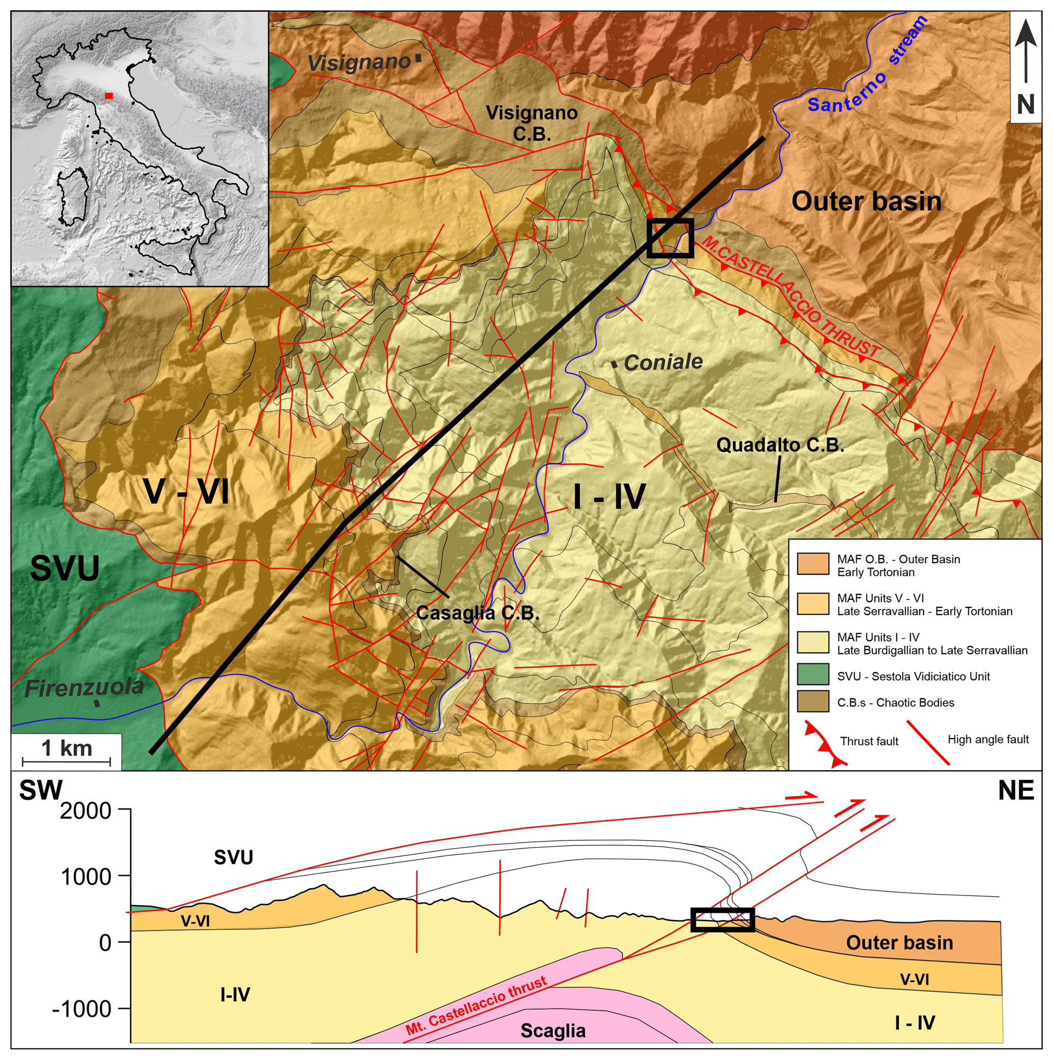
Figure 1Geological map and cross section of the area crossed by the Santerno stream where the Palazzuolo anticline, the Mt. Castellaccio thrust and the studied area (black rectangle) are located (modified after Tinterri and Tagliaferri, 2015).
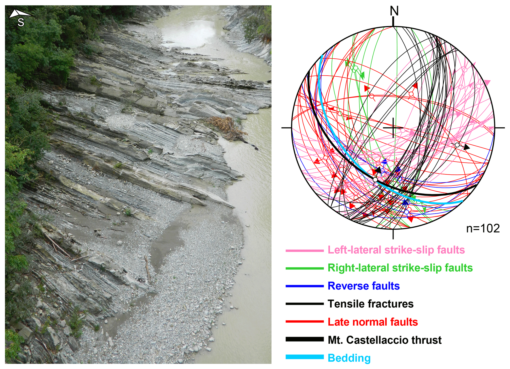
Figure 2Outcrop view of the studied MAF layers along the banks of the Santerno stream. The stereonet represents the five main faults families recognized within the study area on a Schmidt (lower hemisphere) diagram. In addition, tensile fractures are plotted separately from the fault family they belong to (left-lateral strike-slip faults), adding support to the topics discussed hereafter.
The studied portion of the MAF was affected by mid-to-Late Miocene syn-depositional tectonic shortening, partially responsible for the closure of the foredeep basin and, in the area of study, the development of the Palazzuolo anticline, one of the largest and best outcropping contractional structures of the northern Apennines. The Palazzuolo anticline developed at a relatively shallow crustal level recording syn-deformational T < ∼100–110 ∘C (Carlini et al., 2017) and is interpreted as a fault-propagation fold, whose latest development relates to the activity of the nearby out-of-sequence Mt. Castellaccio thrust probably during the Messinian–Pliocene time interval (Carlini et al., 2017; Landuzzi, 2004). During the Late Miocene, syn-contractional low-angle extensional tectonics started to affect the northern Apennines' orogenic wedge at different structural levels (Molli et al., 2018; Clemenzi et al., 2015; Carlini et al., 2013; Jolivet et al., 1998) dramatically reshaping the belt compression-related architecture. In the study area, tectonic thinning was mainly accommodated by the Sestola–Vidiciatico Unit (SVU), a ∼500 m thick shear zone separating the uppermost ocean-derived Late Cretaceous to mid-Eocene Ligurian units from the underlying foredeep deposits of the MAF (Bettelli et al., 2012). Since the Pliocene, most of the chain has been affected at shallow structural levels (< 15 km) by the still-ongoing and seismogenic predominantly NE–SW high-angle extensional tectonics, as testified by seismicity and GPS data (Eva et al., 2014; Bennett et al., 2012; Cenni et al., 2012). Only the deepest portion (> 15 km) of the orogenic wedge and the outermost domains of the northern Apennines (buried beneath the Po Plain), instead, are still affected by a NE–SW-oriented and seismogenic thrusting regime. Still poorly understood strike-slip faulting, moreover, affects selected portions of the wedge and has been tentatively connected with the deep dynamics of the subducting slab (e.g. Piccinini et al., 2014 and references therein).
Our study concentrated on the northeastern front of the Palazzuolo anticline along the right bank of the Santerno River, on an approximately 200 m long and 10 m wide outcrop (Fig. 2). In the study area, MAF layers are characterized by an average thickness of ca. 15 cm and a slightly overturned attitude (average bedding attitude 54/223–dip/dip direction) due to folding. The average composition of MAF layers is given by a feldspathic-/lithic-rich detrital component (quartz: 57.8 %, feldspar: 24.6 %, lithics: 17.6 %) and a fine-grained lithic component containing equal contributions of metamorphic (Lm) and sedimentary/carbonate (Ls) fragments and a lower content in volcanic fragments (Lv) (Lm: 52.3 %, Ls: 42.5 %, Lv: 5.2 %; Benini et al., 2014). Ls fragments are partially composed of varying amounts of phyllosilicates such as muscovite, illite, kaolinite and chlorite. Experimentally determined mechanical parameters are available for both lithologies, yielding not-too-dissimilar values for the sandstone (shear strength C=19 MPa, friction coefficient φ=46∘) and the mudstone (C=13 MPa; φ=40∘; Lembo Fazio and Ribacchi, 1990).
3.1 Paleostress analysis
Numerous striated fault planes were studied and characterized at the outcrop by systematically collecting fault-slip data. A classic paleostress analysis was performed by the analytical approach offered by the Win-Tensor software (Delvaux and Sperner, 2003), which inverts fault kinematic data to compute the reduced stress tensor that best accounts for a given fault population, fully defined by the orientation of σ1, σ2, σ3 and R (the stress shape ratio), defined as
The best fit between the calculated stress tensor and the observed fault-slip data is obtained by a progressive rotation of the computed stress tensor to minimize the misfit angle α between the orientation of the observed fault striae and the maximum computed shear stress resolved on the fault plane. The optimization of the misfit angle is obtained by minimizing the normal stress and maximizing the shear stress acting on the studied fault plane. In our study, the maximum acceptable misfit angle was set to 30∘, as suggested by Ramsay and Lisle (2000). Additionally, we calculated the modified stress regime R′ parameter (Delvaux et al., 1997) because it univocally identifies the stress regime resulting from the paleostress analysis with a number ranging from 0 to 3 and is directly derived from the stress ratio R as shown in Fig. 3.
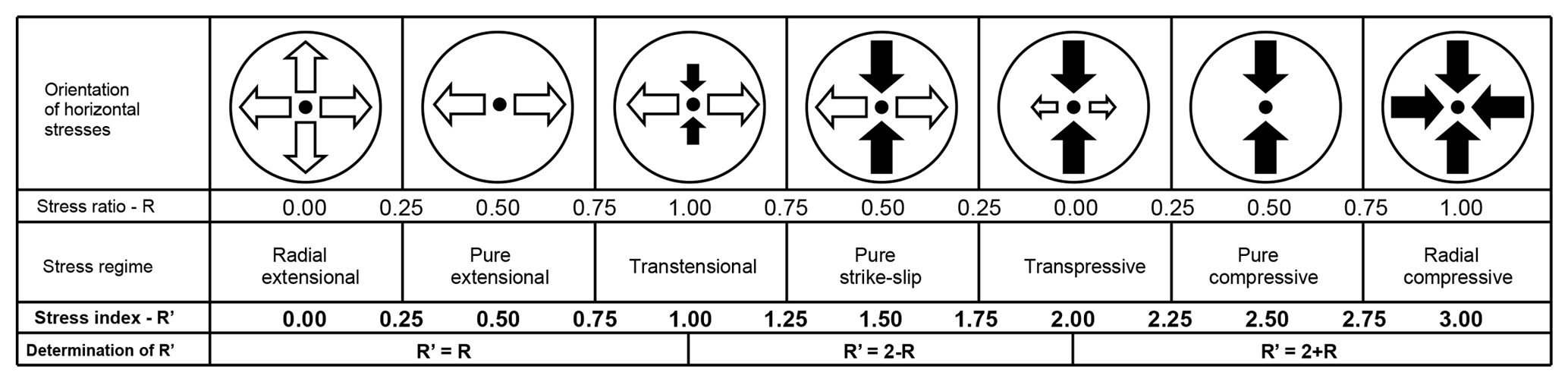
Figure 3Orientation of horizontal principal stresses for different stress regimes and how they are identified by the stress ratio (R) and the stress index (R′). For each stress regime, the relation between R′ and R is also shown (modified after Delvaux et al., 1997).
3.2 Slip tendency analysis
Slip tendency (Morris et al., 1996) is defined as the ratio of shear stress to normal stress on a fracture plane, and slip tendency analysis can be employed in the assessment of fracture orientations that are the most likely to develop by shear fracturing in a given stress field. A prerequisite for the analysis is, obviously, that the stress tensor is known. Dilation of fractures, on the other hand, is controlled by the normal stress σn, and a qualified prediction of the most likely orientations for fracture dilation can be generated by dilation tendency analysis. Dilation tendency (Dt) is defined by Ferrill et al. (1999) as
The orientation of the principal stress axes and the corresponding stress ratio (R) were derived from paleostress analysis and used to calculate slip and dilation tendencies with a Matlab® script following the method proposed by Lisle and Srivastava (2004).
4.1 Field data
Within the analysed area, the MAF deformed in a completely brittle manner and contains faults that we assign to five different families on a geometric and kinematic basis (Figs. 2 and 4): (1) SE to SSE steeply dipping refracted left-lateral strike-slip faults; (2) SW steeply dipping right-lateral strike-slip faults; (3) SW steeply-to-shallowly dipping reverse faults; (4) SW-dipping bedding-parallel faults and (5) N–NE and W–SW shallowly-to-steeply dipping low- and high-angle normal faults. ESE to SE moderately and steeply dipping dilatant tensile fractures are also present. None of the observed fault families contain a significant damage zone, not even within the weak mudstone layers (Figs. 4 and 5). Fault cores within the weak layers are usually very thin, less than 1 cm thick, and are occasionally coated with calcite. For the more mature faults, however, calcite forms a thicker infill (∼1–5 cm; Fig. 5d). In the case of the most significantly refracted faults, the thickness of the fault core changes dramatically as a function of the failure mode observed within the different mechanical layers (see Sect. 4.3 for details; Fig. 5).

Figure 4Field examples of the main fault families recognized within the study area. (a) Steeply dipping refracted left-lateral strike-slip faults. (b) Steeply dipping right-lateral strike-slip faults. (c) Steeply-to-shallowly dipping reverse faults. (d) Bedding-parallel faults crosscutting and generally post-dating strike-slip faults. (e) Shallowly-to-steeply dipping low- and high-angle normal faults.
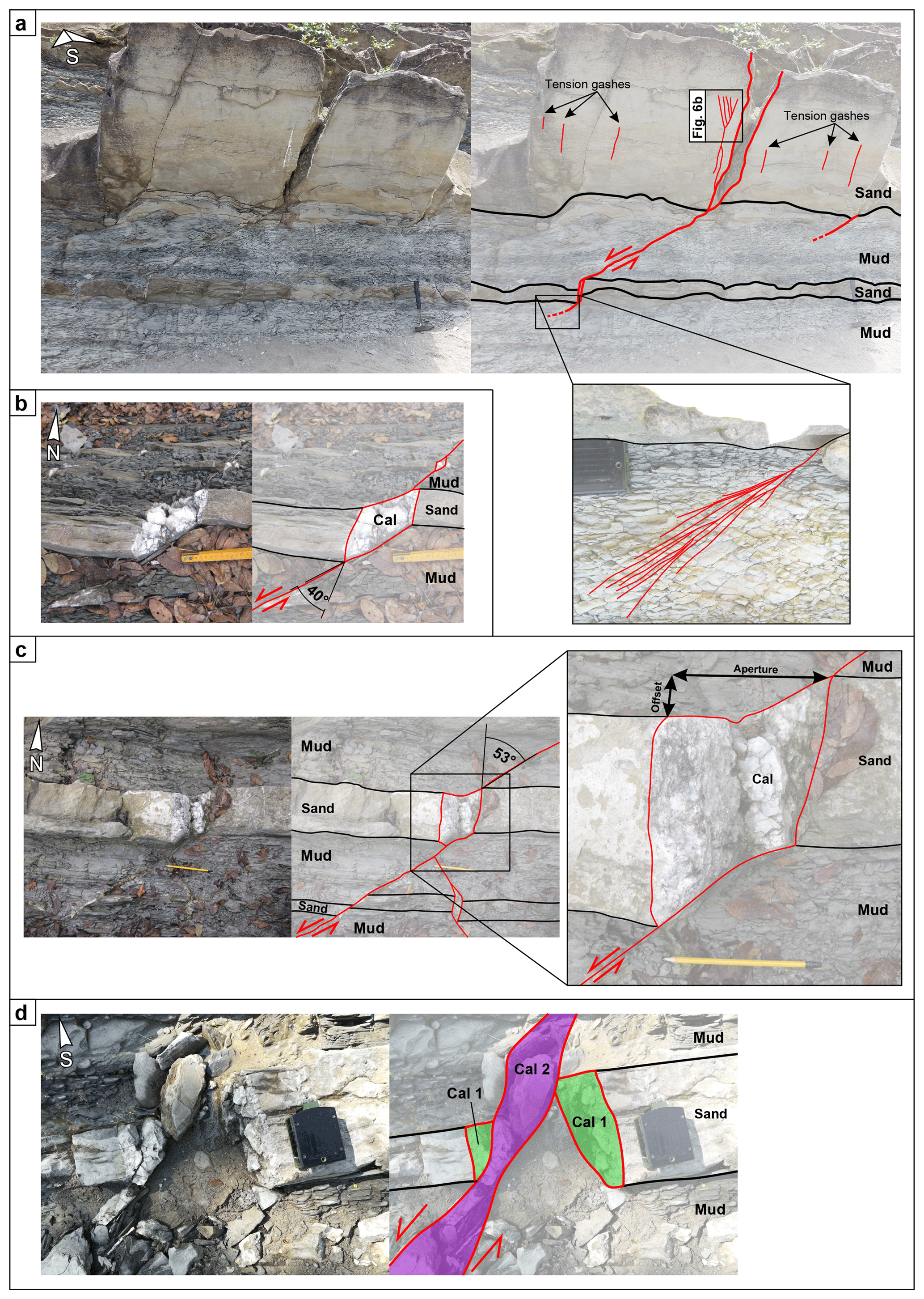
Figure 5Field examples of refracted strike-slip faults. Almost all the photos are taken in plan view. “Sand” is sandstone, “mud” is mudstone and “cal” is calcite. (a) Comprehensive view of a refracted fault with highlighted the presence of vertical tensile gashes and the horsetail geometry of one of the two tips of the fault. (b, c) Details about the tensile fractures within the sandstone layers, highlighting the geometry, the refraction angle and how aperture and offset have been measured (represented in Fig. 7). (d) Example of refracted fault with larger displacement. The coloured areas numbered 1 and 2 indicate different generations of calcite veins, with 1 related to the infill of tensile fractures within sandstone layers and 2 related to the subsequent infill of the more evolved through-going shear fault.
The relative chronology of the faulting events in relation to the development of the Palazzuolo anticline and the Mt. Castellaccio thrust remains loosely constrained and difficult to unravel, even though the observed strike-slip and reverse faults appear to be syn- to shortly post-anticline. Importantly, we note that the refracted strike-slip faults and the reverse faults are spatially restricted to an area of a few hundred m2 just at the front of the Palazzuolo anticline, thus strongly suggesting a genetic relationship between their nucleation and further development and the shortening responsible for the amplification of the anticline as a fault-related fold.
No clear crosscutting relationships among the different fault families were observed, with the exception of the faults that clearly reactivate the tensional fractures (that patently post-date the refracted faults) and the high-angle extensional faults that cut and post-date all other observed brittle structures.
Mesoscopic analysis of refracted strike-slip faults
The analysed strike-slip FFPs are mostly left lateral, but a few dextral planes also occur (Fig. 4b). They all exhibit strong refraction in correspondence of the compositional–mechanical interface between weak (mudstone) and strong (sandstone) layers (Fig. 5a, b and c). Their associated displacement progressively decreases from the strong to the weak layers, where their tips are located, and the FFPs splay into a typical horsetail geometry (Fig. 5a). Within the mudstone layers, deformation is more diffuse and is accommodated by a fracture cleavage mostly oriented at high angle to the bedding and to the localized refracted faults. These fractures are generally barren of calcite infill (Fig. 5a).
Hybrid tensile–shear fractures are invariably found within the strong layers and are characterized by an aperture of between 4 and 20 cm and accommodate a lateral offset from 1 to 20 cm (Figs. 5a and 7). They contain blocky euhedral calcite without any indication of progressive and/or directional opening. Seldomly, they bear slip indicators on the high-angle surface between calcite infill and host rock, indicating a component of shear acting after fracture development and calcite infill. The thickness of the fault core of the refracted faults is usually < 0.5 cm in mudstone layers, but it abruptly increases in the sandstone layers. The strong layers locally exhibit evenly spaced vertical tension gashes (i.e. dilatant calcite-filled fractures elongated along the vertical σ2 direction) that are neither interconnected nor connected to other shear fractures/faults. The main shear FFPs usually develop at about 30∘ to σ1 (Fig. 5a) and they do not link any interconnected “en échelon” segments.
The thickness of the sandstone and mudstone layers and their grain size both appear to play a role in controlling the geometry of the refracted FFPs. Concerning the thickness, the acute angle between the refracted FFPs and bedding within mudstone layers varies between 60 and 30∘ (average 45.5∘), as a function of the thickness of the layers. The trajectory of FFPs is not affected by the competence contrast between neighbouring layers when the thickness of the sandstone layer is < 5 cm. Nonetheless, this first-order relationship appears to be locally overruled by the effect played by the grain size of the deformed lithotype. In some cases, for example, FFPs are refracted even at the interface between mudstone and 3 cm thick coarse-grained sandstone layers, while, in other cases, fine-grained sandstone layers up to 10 cm thick are cut by through-going faults without any refraction. When the total amount of displacement is > ∼50 cm, i.e. when the faults are at a more “mature” stage (see discussion below), the thickness of the fault core increases, while the refracted geometry tends to become less evident until it becomes fully obliterated by the increase in displacement along the fault plane (Fig. 5d).
Several lines of evidence constrain the progressive spatial evolution of the refracted FFPs through the multilayer. FFPs exhibit well-developed shear planes within the mudstone layers that propagate also through the sandstone layers but without completely cutting through them (Fig. 6). In some cases, the slip plane refracts at the mechanical interface between weak and strong layers, becoming almost at right angle to the bed, and is deformed by calcite-filled tensile fractures within the finest portion of the sandstone layers (Fig. 6a and b). Still within strong layers, however, these structures exhibit a second-order refraction in domains where the grain size changes quite abruptly in the sandy beds, producing a branching geometry in the coarsest portion of the layers, characterized by the presence of both tensile and hybrid fractures (Fig. 6a and b). These two types of fractures have been discriminated on the basis of θ (angle between σ1 and fracture), with it being close to 0∘ for the mode I openings (i.e. fractures parallel to the maximum compressive stress) and between 0 and 30∘ for the hybrid shear planes. In other cases, faults propagating through the sandstone layers produce a complex network of calcite-filled fractures with angular and unsorted fragments of rock that are only partially dislodged from the host rock (Fig. 6c).
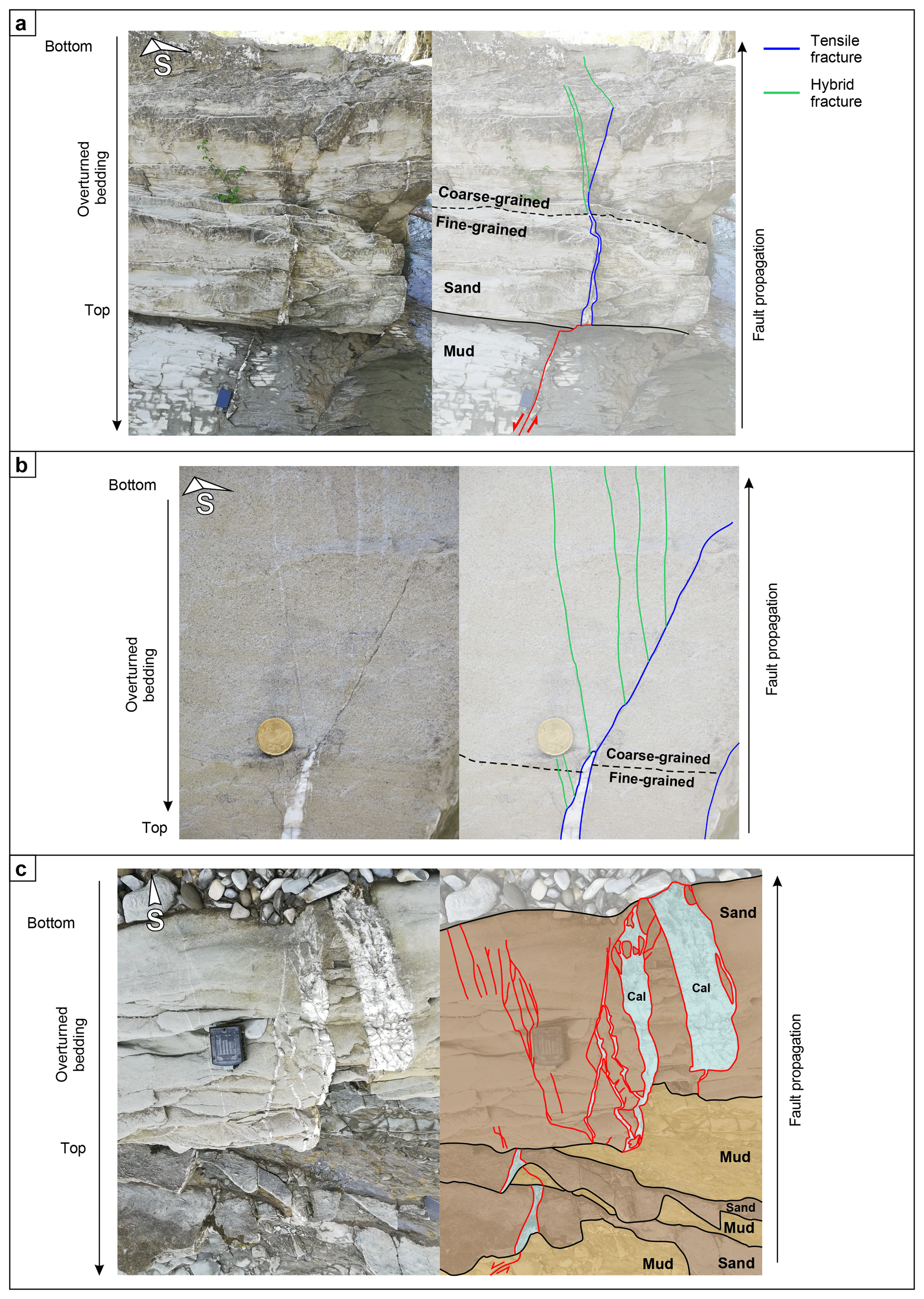
Figure 6Field examples showing evidences of refracted faults at different stages of evolution. “Sand” is sandstone, “mud” is mudstone and “cal” is calcite. Tensile fractures are represented in blue, while hybrid fractures are represented in green. (a, b) Well-developed shear fault propagating from weak layers (bottom part of the picture) within the strong layers. Here, the fractures show a second-order refraction; deformation moves from tensile failure (orthogonal to the bedding) to a branching geometry corresponding to an abrupt grain-size change (see Fig. 5a for location of panel b). (c) Another example of evolving refracted faults that propagate through the sandstone layers creating a complex network of calcite-filled fractures and fragmented slices of rock. Colours are added to further help to distinguish sandstone and mudstone layers and calcite-filled veins.
We derived geometrical scaling relationships to better characterize the tensile and shear components of the hybrid fractures within the strong layers. Figure 7 plots the thickness of strong layers vs. the aperture of the dilational segments of the refracted FFPs (tensile component) vs. offset (shear component). Although with a significant variance (see the low correlation coefficient), the data indicate a weak linear correlation for all data sets. The main reason for this dispersion is that the measured aperture and offset, as previously stated, strongly depend also on grain size and clay mineral content, which vary, at times significantly even within the same layer.
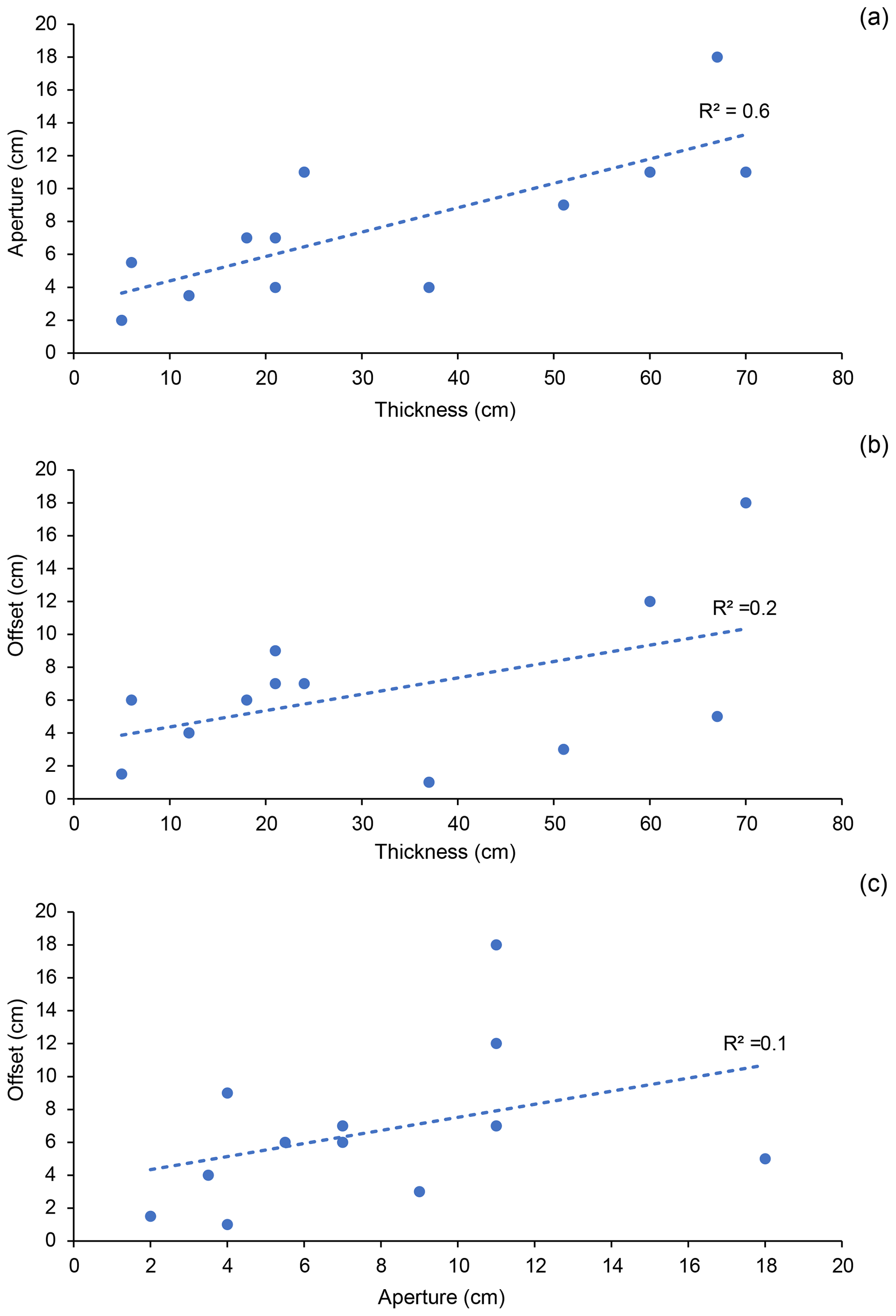
Figure 7Representation of the relationships between different geometrical parameters measured on the dilational segments of FFPs. (a) thickness vs. aperture of the strong layers; (b) thickness vs. offset (or displacement) of the sandstone layers; (c) aperture vs. offset of the dilational fractures. The large scattering is probably due to the fact that the measured parameters are not normalized to the actual grain size of the strong layers; see text for explanation.
4.2 Paleostress analysis
Paleostress analysis was performed to constrain realistic stress tensors capable of accounting for the observed faults and to elucidate the possible genetic relationships between the computed paleostress tensor and the regional stress field that produced the Palazzuolo anticline within the overall north Apennines shortening framework. We did not include the high-angle extensional faults in this analysis because they are interpreted as the most recent tectonic features and basically unrelated to the other studied faults (see also Sect. 2).
Results suggest that all the documented faults can be reasonably ascribed to a single strike-slip stress field (), characterized by a subvertical σ2 and a σ1 oriented 026/08 (Fig. 8a), very similar to the shortening direction required for the formation of the Palazzuolo anticline.
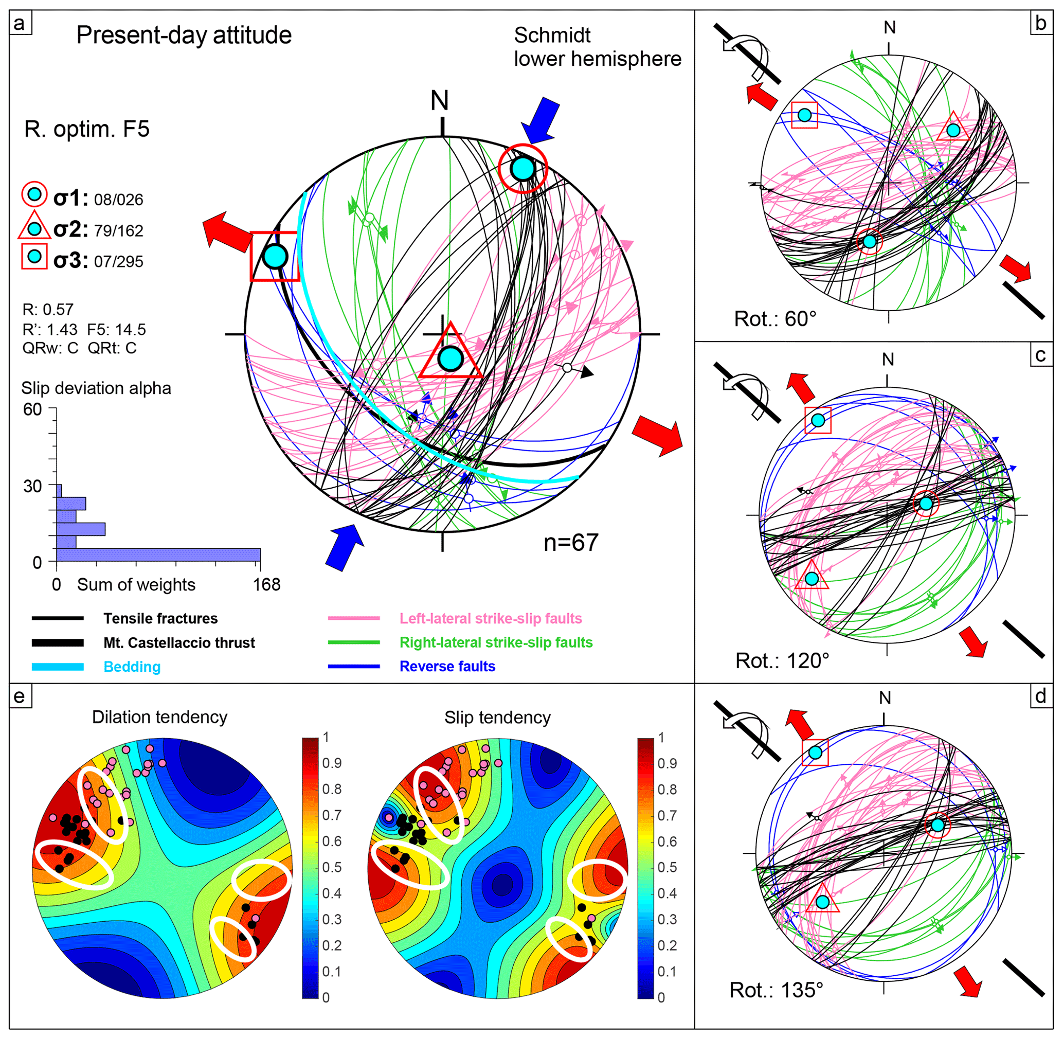
Figure 8(a) Paleostress tensor calculation accounting for the present-day attitude of the left- and right-lateral strike-slip faults, dilatant fractures, reverse faults and main Mt. Castellaccio thrust. The blue and red arrows, together with the principal stress symbols, describe the orientation of the paleostress ellipsoid. The histogram represents the misfit of the faults' attitude with respect to the paleostress tensor. (b–d) Rotation of the fault-slip data (and related paleostress tensor) with respect to the 130/00-oriented main axis of the Palazzuolo anticline. Each panel represents a rotation of 60∘, except the last one (d), which represents a rotation to a complete horizontal attitude of the bedding. (e) Results of the slip tendency analysis. The coloured scale represents how prone the measured faults are to reactivation, either in dilation or shear. White circles represent areas of high dilation tendency and high slip tendency; see text for explanation.
Given the current vertical-to-overturned attitude of the beds at the studied outcrop, to exclude the possibility that the refracted faults formed at a different orientation and were only later reoriented during the development of the Palazzuolo anticline, we rotated them coherently with the bedding until the latter attained a horizontal attitude, thus mimicking a possible pre-anticline setting. This restoration, carried out in progressive steps of 60∘, was performed around a horizontal axis striking 130∘, i.e. parallel to the local average orientation of the Palazzuolo anticline axis (Fig. 8b–d). In the pre- to syn-Palazzuolo anticline folding stage (Fig. 8d), the sinistral and dextral strike-slip faults become moderately dipping top to the NW and SE extensional faults, respectively, and the tensile fractures strike ENE–WSW. Restoration leads to faults that could thus be the expression of a NW–SE extensional stress field. We note, however, that the average dihedral angle between the two fault families is > 80∘, which would imply strongly non-Andersonian conditions during this potential pre-folding extensional event and thus argues against them being conjugate structures. Additionally, the existence of this NW–SE pre- to syn-folding extensional phase is not documented or supported by any systematic and convincing independent geological evidence for the studied portion of the northern Apennines. We conclude, therefore, that the refracted strike-slip faults are a local expression of the Palazzuolo anticline nucleation and amplification and that, as such, they are coeval with or post-date the development of the fold. They developed within a strike-slip stress field, with σ1 oriented 026∕08.
4.3 Slip tendency analysis
By using the reduced stress tensor constrained by our paleostress analysis, it was possible to compute slip and dilation values for every orientation and to assess the relative slip and dilation potentials of the structures observed within the study site. As the tendency computations are based on paleostress analysis, it is to be expected that shear fractures attain highest slip tendency values and tensional fractures highest dilation tendency values. The usage of slip and dilation tendency analysis, however, makes it possible to further assess the effect of the stress ratio upon faulting, which, in the extreme case of values close to 0 or 1, may result in counterintuitively high slip and dilation tendency values for specific orientations (e.g. Morris and Ferrill, 2009; Leclère and Fabbri, 2013). The results of our tendency analysis show that the observed tensile fractures (related to the refracted strike-slip faults; black dots in Fig. 8e) have relatively low slip tendency, but high dilation tendency, with the highest values for fractures with an average attitude of 20∕300, which suggests fracture opening parallel to the interpreted σ3 direction (Fig. 8e). As for the sinistral refracted faults (pink dots in Fig. 8e), the steeper faults have an average pole attitude of 315∕20 and are characterized by high slip tendency and low dilation tendency (Fig. 8e). Interestingly, Fig. 8e shows areas characterized by relatively high slip and dilation tendencies, possibly indicating the existence of shear fractures with a significant dilation component (white circles in Fig. 8e).
The deformed MAF volume to the northeast of the Mt. Castellaccio thrust and related Palazzuolo anticline contains outstanding examples of refracted FFPs that, as revealed by field observations and paleostress analysis, developed within a strike-slip regime with σ1 oriented 026∕08. While refracted normal FFPs are reported in the literature by numerous studies, refracted strike-slip FFPs are not described to the best of our knowledge.
Detailed fieldwork, coupled with the systematic analysis of the geometric and kinematic characteristics and parameters of the studied FFPs and the identification of structures and structural patterns documenting different stages of the local evolution, has allowed us to better understand the mechanical behaviour of the studied strike-slip faults throughout the sedimentary multilayer. The spatially partitioned coexistence of different fracturing modes within the multilayer is best accounted for by a conceptual brittle mechanical model based upon two distinct failure envelopes and related Mohr circles that describe independently (yet contemporaneously) the distinct evolution of the tensile–hybrid and shear fractures within the strong and weak layers, respectively.
Following the initial application of a stress field upon the MAF multilayer, failure first localized in the weak mudstone layers during the build-up of differential stress. This reflects the fact that, while enlarging, the Mohr circle first touches the failure envelope of the mechanically weaker lithotype, i.e. the mudstone (Figs. 5a and 9a). The presence of spatially isolated tension gashes parallel to the σ1–σ2 plane within some sandstone layers cannot be considered as evidence of original nucleation within the strong layers. Our findings suggest them to rather be a localized pre-existing weakness that drives the localization of the tensile component of the refracted faults within strong layers or even structures belonging to a later deformation stage (in both cases formed after the shear fractures within mudstone layers; Fig. 5a).
Once the shear planes propagate further through the multilayer, the rheological contrast causes the refraction at significant interfaces (i.e. either bed–bed interface or intra-bed surface where there occur significant compositional or grain-size variations) and the local mechanical properties control the overall failure mode. Refraction itself, in fact, consists in a change of the angle θ between the orientation of the FFPs and σ1. When θ is close to 0∘, failure takes place primarily by tensile fracturing; for θ up to 25∘, fracturing becomes hybrid, and for θ > 25∘ deformation occurs by shear fracturing. The studied refracted faults within strong layers are characterized by a θ angle between 0 and 20∘, which allows us to classify them as tensile or hybrid fractures as a function of θ itself. Fault propagation through the sandstone layers occurs by the progressive weakening of the volume of rock at the fault tip through structural processing by dilatant and hybrid fractures that progressively develop and connect, allowing the growth of the shear fault plane (i.e. a “process zone”, sensu Fossen, 2010; Fig. 6).
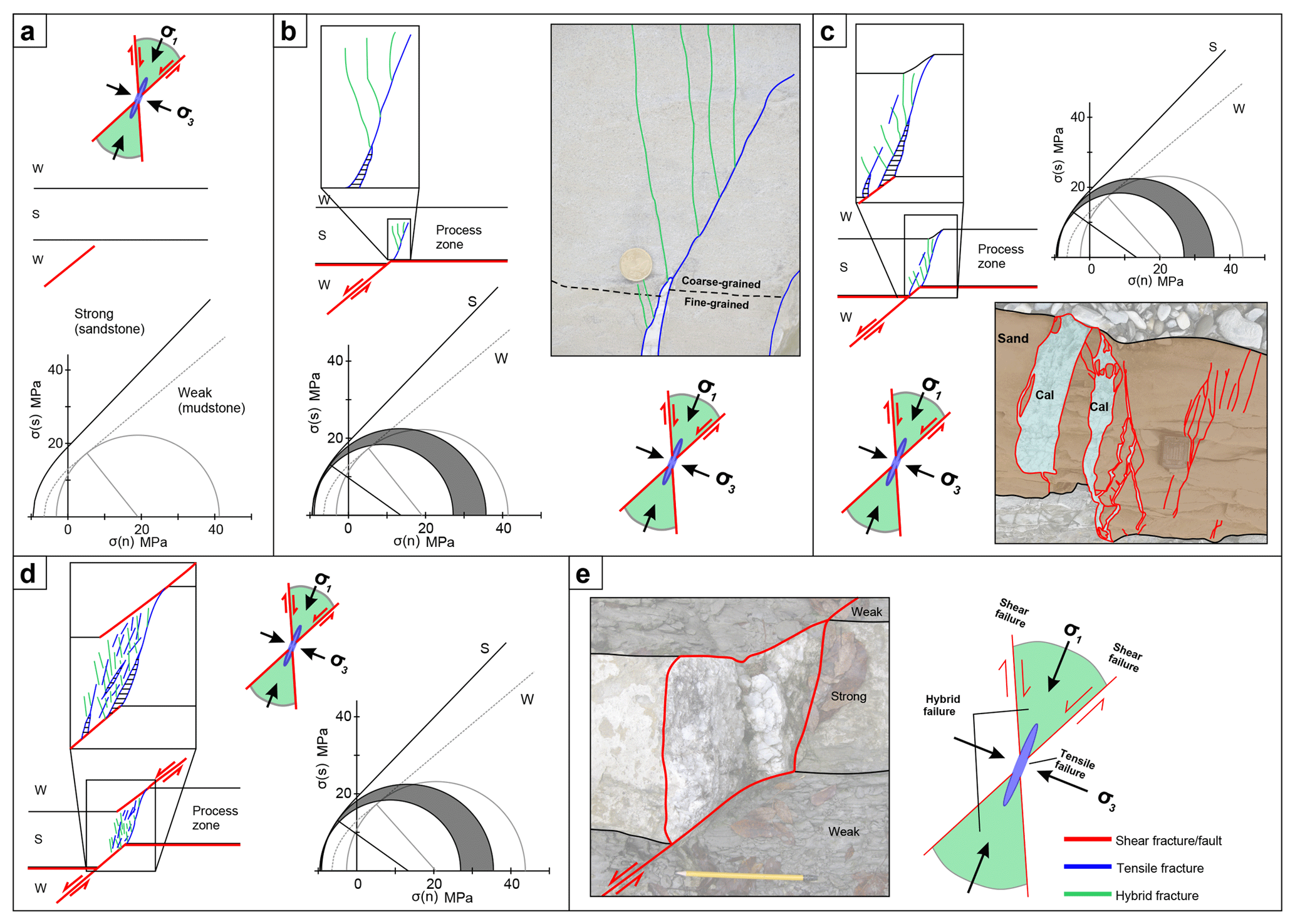
Figure 9Multi-stage conceptual mechanical evolution for the formation and propagation of the studied refracted faults, coupled with Mohr diagrams; see text for explanation. Cohesion (C), tensile strength (T) and angle of internal friction (φ) for the sandstone and mudstone lithologies were obtained by laboratory triaxial experiments performed on the MAF sandstone and mudstone layers (Lembo Fazio et al., 1990). Black failure envelope and Mohr circle refer to sandstone; grey dashed envelope and circle refer to mudstone. The grey areas tentatively represent the differential stress span existing between ideal conditions for development of tensile (lower differential stress) and hybrid (higher differential stress) fractures within sandstone layers. During “processing” of the strong sandy layers at the tip of the growing and propagating fracture plane, stress conditions switch cyclically and repeatedly between these two end-member scenarios.
Our detailed mesoscopic observations have led us to conceptualize a model for the mechanical behaviour and evolution of the studied strike-slip refracted faults. We illustrate it in the following by also referring to Fig. 9, where every step is illustrated by a Mohr–Coulomb diagram and a picture representing the corresponding structure/stage as observed in the field:
-
The studied faults nucleate initially as shear fractures within mudstone layers. Nucleation therein reflects failure during regional and local stress build-up because of the lower mechanical strength of mudstone. The different mechanical properties of strong and weak layers, at this early stage, allow the elastic storage of stress within the sandstone layers before failure, while mudstone layers reach their yield point earlier through a more “plastic” behaviour (Fig. 9a; e.g. Giorgetti et al., 2016).
-
When the FFPs propagate from the weak layer toward adjacent strong layers and reach the planar layer–layer interface, they refract because of the different mechanical properties of the stronger sandstone (e.g. Ferrill et al., 2012). The presence of thin calcite films along bed–bed interface parallel faults suggests a dilational component at a high angle to the layering indicative of a partial decrease of the normal stress, possibly reflecting a decrease of effective stress (i.e. a decrease in mean stress), a condition necessary for the first tensile–hybrid fractures to occur within the strong layers (Fig. 9b). These first fractures document the progressive formation of a hybrid process zone ahead of the tips of the FFPs. Importantly, the presence of calcite infill also in the tensile fractures formed during this incipient deformation stage of the strong sandstone layers confirms that fluids may indeed have played a role in further lowering the mean stress. Precipitation and crystallization of calcite allows also for a partial recovery of shear stress within the sandstone layers, which leads to more suitable conditions for the formation of hybrid fractures. Unfortunately, we lack clear-cut evidence to establish whether it is the tensile or hybrid fractures to develop first. In any case, the well-documented coexistence of tensile and hybrid FFPs implies that from this stage onwards the deformation of strong layers becomes complex and dynamic, switching cyclically and repeatedly between two different stress conditions. Since shear deformation is still active within the weak layers, a differential mechanical behaviour is required also at the scale of the deforming multilayer, wherein the deformation histories of the two involved lithologies evolve partially independent of each other. This requires adopting two failure envelopes and two related transient Mohr circles, despite a single background regional stress field.
-
As deformation continues, fragmentation within the process zone increases, creating a complex network of intersecting fractures and dislodging host rock fragments, which end up being trapped within the tensile and hybrid fracture calcite vein infill (Fig. 9c). At this stage, deformation of the process zone is not mature enough to have the fault propagate further to the next weak layer yet.
-
The process zone then becomes totally disrupted to facilitate enhanced fluid flow and calcite precipitation and to have the FFPs cut through the sandstone layer and propagate toward the next weak layer (Fig. 9d). The volume of the dilated process zone infilled by calcite veins becomes significantly larger as strain progressively accumulates.
-
The final stage is characterized by the development of one major, through-going fracture within the strong layer, with the dilatant segment in the competent layer fully filled by calcite. The pervasive deformation style of the mature FFP propagation could potentially obliterate all evidence of the earlier deformation stages (Fig. 9e).
The shallow crustal level at which deformation occurred (see also Sect. 2) suggests that the studied refracted strike-slip faults developed under relatively low differential stress. This and the total lack of structures testifying extreme fluid pressure conditions (e.g. hydraulic breccias) do not allow to estimate the extent to which (overpressured?) fluids assisted the deformation process. On the one hand, in fact, (over)pressured fluids at depth migrate vertically along planes tracking the σ1 and σ2 principal stresses, perpendicularly to σ3 within the open fractures, at least partially driven by the negative pressure gradient caused by the opening of the tensile fractures themselves. On the other hand, fluid pressure probably contributes to lowering the mean stress sufficiently for tensile and hybrid fractures to form. In both cases, what our detailed field observations and our conceptual model highlight is that circulation of pressured fluids quite certainly controlled the localization, development and propagation of the studied strike-slip, refracted faults together with grain size, mineralogy (especially the content of clay minerals) and mechanical properties of the fracturing rock (cohesion, angle of internal friction and tensile strength).
Even though the final geometry and some of the mechanical aspects steering the evolution of the studied strike-slip faults are similar to those described in the literature for normal faults, a straightforward comparison of our conceptual model to the classic schemes for normal faults as summarized in Sect. 1 is not possible because
-
the strike-slip tectonic regime implies important differences in the orientation of both stress and strain ellipsoids; and
-
intermediate stages of development of refracted faults are rarely observed in extensional faults, leaving uncertainties about the details of initial strain localization and deformation history of refracting faults and fractures.
In summary, our results therefore help to clarify important details of the intermediate steps of the evolution of refracted faults and fractures, indicating an alternative mechanical model to that generally proposed for extensional faults.
Moreover, our study highlights the details of possible modes of strike-slip fault initiation and development in a sedimentary sequence characterized by layers of contrasting properties and the dynamic stress conditions prevailing during propagation of the faults, which also results in refracted strike-slip faults. This might be useful to studies dealing with strike-slip faulting at all scales in sedimentary sequences, including the segmentation of strike-slip faults and the formation and development of step-overs as the faults grow by progressively accumulating slip. Fault segmentation (e.g. Manighetti et al., 2009) has great implications on the mechanical behaviour of faults and our model provides important constraints on the seismic hazard assessment of such environments. The formation of dilational step-overs also has implications for fluid flow within faults and adjacent rock volumes, and our model may provide indications on the location and characteristics of the potential dilational jogs and areas of enhanced permeability leading to enhanced fluid flow and mineral precipitation.
Our study on refracted strike-slip faults aimed to address and give new constraints on fundamental questions concerning the details of nucleation and propagation of FFPs, development of hybrid fractures and the processes governing the transition between different fracturing modes (tensile, hybrid and shear). It has highlighted the crucial role played by the heterogeneous mechanical properties of alternating strong and weak lithologies in deviating FFP trajectories and causing the localized coexistence of different failure modes. The recognition of clear geological structures describing the incipient and/or intermediate evolution stages of the studied strike-slip refracted FFPs has allowed us to conclude the following:
-
Nucleation occurs within weak layers.
-
Refraction and its magnitude are mainly controlled by grain size and content in clay minerals, which in turn steer mechanical properties such as shear and tensile strength and friction coefficient of the involved lithologies.
-
Propagation occurs by the fluid-assisted development of a complex process zone within strong layers in front of the tip of the growing FFPs.
-
The process zone is characterized by a network of coexisting tensile and hybrid fractures that evolve, through progressive weakening and fragmentation of the affected rock volume, into a tensile fracture completely filled by calcite, suggesting a transient cyclical increase and decrease of the local differential stress as failure is accommodated by cyclic tensile and hybrid failure modes.
-
Pressured fluids play an important role in achieving suitable conditions for the development of tensile and hybrid fractures.
Detailed information on the outcrop as well as the raw data can be obtained by contacting the corresponding authors.
GV and MC conceptualized the study by identifying the outcrop and studying it in detail. LC contributed to the paleostress analysis as part of his Bachelor of Science project. JM wrote the script for dilation and slip tendency analysis and helped with discussing and refining the mechanical model. MC and GV wrote the text with contributions from JM.
The authors declare that they have no conflict of interest.
We thank Andrea Billi and an anonymous reviewer for their advice and
constructive criticism, and Mark Allen for handling the editorial process.
Edited by: Mark Allen
Reviewed by: Andrea Billi and one anonymous referee
Agosta, F., Wilson, C., and Aydin, A.: The role of mechanical stratigraphy on normal fault growth across a Cretaceous carbonate multi-layer, central Texas (USA), Ital. J. Geosci., 134, 423–441, https://doi.org/10.3301/IJG.2014.20, 2015.
Benini, A., Martelli, L., Poccianti, C., Rosselli, S., Benvenuti, M., Catanzariti, R., Giulio, A. Di, Gargini, A., and Fornaciari, E.: Note Illustrative della Carta Geologica d'Italia – foglio 253 Marradi, Regione Emilia Romagna – Servizio Geologico, Sismico e dei Suoli, 2014.
Bennett, R. A., Serpelloni, E., Hreinsdóttir, S., Brandon, M. T., Buble, G., Basic, T., Casale, G., Cavaliere, A., Anzidei, M., Marjonovic, M., Minelli, G., Molli, G., and Montanari, A.: Syn-convergent extension observed using the RETREAT GPS network, northern Apennines, Italy, J. Geophys. Res., 117, 1–23, https://doi.org/10.1029/2011JB008744, 2012.
Bettelli, G., Panini, F., Fioroni, C., Nirta, G., Remitti, F., Vannucchi, P., and Carlini, M.: Revisiting the geology of the “Sillaro line”, Northern Apennines, Italy, Rend. Online Soc. Geol. Ital., 22, 14–17, 2012.
Carlini, M., Artoni, A., Aldega, L., Balestrieri, M. L., Corrado, S., Vescovi, P., Bernini, M., and Torelli, L.: Exhumation and reshaping of far-travelled/allochthonous tectonic units in mountain belts, New insights for the relationships between shortening and coeval extension in the western Northern Apennines (Italy), Tectonophysics, 608, 267–287, https://doi.org/10.1016/j.tecto.2013.09.029, 2013.
Carlini, M., Storti, F., Balsamo, F., Clemenzi, L., Ogata, K., Aldega, L., Corrado, S., Tagliaferri, A., Tinterri, R., and Viola, G.: Tectono-sedimentary evolution of the Palazzuolo anticline (Northern Apennines – Italy), Geophysical Research Abstracts, 19, EGU2017-17123-2, EGU General Assembly, 2017.
Cenni, N., Mantovani, E., Baldi, P., and Viti, M.: Present kinematics of Central and Northern Italy from continuous GPS measurements, J. Geodyn., 58, 62–72, https://doi.org/10.1016/j.jog.2012.02.004, 2012.
Clemenzi, L., Storti, F., Balsamo, F., Molli, G., Ellam, R., Muchez, P., and Swennen, R.: Fluid pressure cycles, variations in permeability, and weakening mechanisms along low-angle normal faults: The tellaro detachment, Italy, Bull. Geol. Soc. Am., 127, 1689–1710, https://doi.org/10.1130/B31203.1, 2015.
Delvaux, D., Moeys, R., Stapel, G., Petit, C., Levi, K., Miroshnichenko, A., Ruzhich, V., and San'kov, V.: Paleostress reconstructions and geodynamics of the Baikal region, Central Asia, Part 2, Cenozoic rifting, Tectonophysics, 282, 1–38, https://doi.org/10.1016/S0040-1951(97)00210-2, 1997.
Delvaux, D. and Sperner, B.: New aspects of tectonic stress inversion with reference to the TENSOR program, Geol. Soc. London, Spec. Publ., 212, 75–100, https://doi.org/10.1144/GSL.SP.2003.212.01.06, 2003.
Eva, E., Solarino, S., and Boncio, P.: HypoDD relocated seismicity in northern Apennines (Italy) preceding the 2013 seismic unrest: Seismotectonic implications for the Lunigiana-Garfagnana area, Boll. di Geofis. Teor. ed Appl., 55, 739–754, https://doi.org/10.4430/bgta0131, 2014.
Ferrill, D. A. and Morris, A. P.: Dilational normal faults, J. Struct. Geol., 25, 827, https://doi.org/10.1016/S0191-8141(02)00196-7, 2003.
Ferrill, D. A., Winterle, J., Wittmeyer, G., Sims, D., Colton, S., Armstrong, A., and Morris, A. P.: Stressed rock strains groundwater at Yucca Mountain, Nevada, GSA Today, 9, 1–8, 1999.
Ferrill, D. A., McGinnis, R. N., Morris, A. P., and Smart, K. J.: Hybrid failure: Field evidence and influence on fault refraction, J. Struct. Geol., 42, 140–150, https://doi.org/10.1016/j.jsg.2012.05.012, 2012.
Ferrill, D. A., Morris, A. P., McGinnis, R. N., Smart, K. J., Wigginton, S. S., and Hill, N. J.: Mechanical stratigraphy and normal faulting, J. Struct. Geol., 94, 275–302, https://doi.org/10.1016/j.jsg.2016.11.010, 2017.
Fossen, H.: Structural geology, Cambridge University Press, Cambridge, 2010.
Giorgetti, C., Collettini, C., Scuderi, M. M., Barchi, M. R., and Tesei, T.: Fault geometry and mechanics of marly carbonate multilayers: An integrated field and laboratory study from the Northern Apennines, Italy, J. Struct. Geol., 93, 1–16, https://doi.org/10.1016/j.jsg.2016.10.001, 2016.
Hill, D. P.: A model for earthquake swarms, J. Geophys. Res., 82, 1347–1352, https://doi.org/10.1029/JB082i008p01347, 1977.
Jolivet, L., Faccenna, C., Goffé, B., Mattei, M., Rossetti, F., Brunet, C., Storti, F., Funiciello, R., Cadet, J. P., d'Agostino, N., and Parra, T.: Midcrustal shear zones in postorogenic extension: Example from the northern Tyrrhenian Sea, J. Geophys. Res., 103, 123–160, https://doi.org/10.1029/97JB03616, 2018.
Landuzzi, A.: Syn-depositional emplacement of the liguride allochthon in the Miocene foredeep of the Western Romagna Appennines, in: Mapping Geology in Italy, edited by: Pasquarè, G. and Venturini, C., 1–13, S.EL.CA., Firenze, 2004.
Leclère, H. and Fabbri, O.: A new three-dimensional method for fault reactivation, J. Struct. Geol., 48, 153–161, 2013.
Lembo Fazio, A. and Ribacchi, R.: Sheared bedding joints in rock engeneering: two cas histories in Italy, in: Rock Joints, edited by: Barton, N. and Stephansson, O., A. A. Balkema, Rotterdam, the Netherlands, 1990.
Lisle, R. J. and Srivastava, D. C.: Test of the frictional reactivation theory for faults and validity of fault-slip analysis, Geology, 32, 569–572, https://doi.org/10.1130/G20408.1, 2004.
Manighetti, I., Zigone, D., Campillo, M., and Cotton, F.: Self-similarity of the largest-scale segmentation of the faults: Implications for earthquake behaviour, Earth Planet. Sc. Lett., 288, 370–381, https://doi.org/10.1016/j.epsl.2009.09.040, 2009.
Molli, G., Carlini, M., Vescovi, P., Artoni, A., Balsamo, F., Camurri, F., Clemenzi, L., Storti, F., and Torelli, L.: Neogene 3D-structural architecture of the North-West Apennines: The role of the low angle normal faults and basement thrusts, Tectonics, 17, 2165–2196, https://doi.org/10.1029/2018TC005057, 2018.
Morris, A. P. and Ferrill, D. A.: The importance of the effective intermediate principal stress (σ′2) to fault slip patterns, J. Struct. Geol., 31, 950–959, https://doi.org/10.1016/j.jsg.2008.03.013, 2009.
Morris, A. P., Ferrill, D. A., and Henderson, D. B.: Slip tendency analysis and fault reactivation, Geology, 24, 275–278, 1996.
Peacock, D. C. P. and Sanderson, D. J.: Pull-aparts, shear fractures and pressure solution, Tectonophysics, 241, 1–13, https://doi.org/10.1016/0040-1951(94)00184-B, 1995.
Peacock, D. C. P. and Zhang, X.: Field examples and numerical modelling of oversteps and bends along normal faults in cross-section, Tectonophysics, 234, 147–167, https://doi.org/10.1016/0040-1951(94)90209-7, 1994.
Piccinini, D., Piana Agostinetti, N., Saccorotti, G., Fiaschi, A., Matassoni, L., and Morelli, M.: Orogen-parallel variability in 3D seismicity distribution, Northern Apennines (Italy): Evidence for a slab tear fault?, J. Geodyn., 82, 110–117, https://doi.org/10.1016/j.jog.2014.09.005, 2014.
Ramsay, J. G. and Lisle, R. J.: The techniques of modern structural geology, volume 3: Applications of continuum mechanics in structural geology, Elsevier, London, 2000.
Ramsey, J. M. and Chester, F. M.: Hybrid fracture and the transition from extension fracture to shear fracture, Lett. Nat., 428, 63–66, 2004.
Ricci Lucchi, F.: The Oligocene to recent foreland basins of the Northern Apennines, in: Foreland Basins, edited by: Allen P. A., and Homewood, P., 105–139, Blackwell Scientific, Oxford, 1986.
Roche, V., Homberg, C., and Rocher, M.: Fault nucleation, restriction, and aspect ratio in layered sections: Quantification of the strength and stiffness roles using numerical modeling, J. Geophys. Res.-Sol. Ea., 118, 4446–4460, https://doi.org/10.1002/jgrb.50279, 2013.
Roveri, M., Ricci Lucchi, F., Lucente, C. C., Manzi, V., and Mutti, E.: Stratigraphy, facies and basin fill history of the Marnoso-arenacea Formation, in: Revisiting turbidites of the Marnoso-arenacea Formation and their basin-margin equivalents: problems with classic models, edited by: Mutti, E., Ricci Lucchi, F., and Roveri, M., Florence, 2002.
Rudnicki, J. W.: Shear Deformation in Fissured Rock Masses, J. Geophys. Res.-Sol. Ea., 89, 9259–9270, 1984.
Schöpfer, M. P. J., Childs, C., and Walsh, J. J.: Localisation of normal faults in multilayer sequences, J. Struct. Geol., 28, 816–833, https://doi.org/10.1016/j.jsg.2006.02.003, 2006.
Secor, D. T.: Role of fluid pressure in jointing, Am. J. Sci., 263, 633–646, 1965.
Sibson, R. H.: Structural permeability of fluid-driven fault-fracture meshes, J. Struct. Geol., 18, 1031–1042, https://doi.org/10.1016/0191-8141(96)00032-6, 1996.
Sibson, R. H.: Brittle failure mode plots for compressional and extensional tectonic regimes, J. Struct. Geol., 20, 655–660, https://doi.org/10.1016/S0191-8141(98)00116-3, 1998.
Sibson, R. H.: Fluid involvement in normal faulting, J. Geodyn., 29, 469–499, https://doi.org/10.1016/S0264-3707(99)00042-3, 2000.
Sibson, R. H.: Brittle-failure controls on maximum sustainable overpressure in different tectonic regimes, Am. Assoc. Pet. Geol. Bull., 87, 901–908, https://doi.org/10.1306/01290300181, 2003.
Sibson, R. H. and Scott, J.: Stress/fault controls on the containment and release of overpressured fluids: examples from gold-quartz vein systems in Juneau, Alaska; Victoria, Australia and Otago, New Zealand, Ore Geol. Rev., 13, 293–306, https://doi.org/10.1016/S0169-1368(97)00023-1, 1998.
Tinterri, R. and Tagliaferri, A.: The syntectonic evolution of foredeep turbidites related to basin segmentation: Facies response to the increase in tectonic confinement (Marnoso-arenacea Formation, Miocene, Northern Apennines, Italy), Mar. Pet. Geol., 67, 81–110, https://doi.org/10.1016/j.marpetgeo.2015.04.006, 2015.