the Creative Commons Attribution 4.0 License.
the Creative Commons Attribution 4.0 License.
 | 27 Jun 2019
Uncertainty in fault seal parameters: implications for CO2 column height retention and storage capacity in geological CO2 storage projects
Johannes M. Miocic
Gareth Johnson
Clare E. Bond
Faults can act as barriers to fluid flow in sedimentary basins, hindering the migration of buoyant fluids in the subsurface, trapping them in reservoirs, and facilitating the build-up of vertical fluid columns. The maximum height of these columns is reliant on the retention potential of the sealing fault with regards to the trapped fluid. Several different approaches for the calculation of maximum supported column height exist for hydrocarbon systems. Here, we translate these approaches to the trapping of carbon dioxide by faults and assess the impact of uncertainties in (i) the wettability properties of the fault rock, (ii) fault rock composition, and (iii) reservoir depth on retention potential. As with hydrocarbon systems, uncertainties associated with the wettability of a CO2–brine–fault rock system for a given reservoir have less of an impact on column heights than uncertainties of fault rock composition. In contrast to hydrocarbon systems, higher phyllosilicate entrainment into the fault rock may reduce the amount of carbon dioxide that can be securely retained due a preferred CO2 wettability of clay minerals. The wettability of the carbon dioxide system is highly sensitive to depth, with a large variation in possible column height predicted at 1000 and 2000 m of depth, which is the likely depth range for carbon storage sites. Our results show that if approaches developed for fault seals in hydrocarbon systems are translated, without modification, to carbon dioxide systems the capacity of carbon storage sites will be inaccurate and the predicted security of storage sites erroneous.
- Article
(5431 KB) - Full-text XML
- BibTeX
- EndNote


Carbon capture and storage (CCS) is one of the key technologies to mitigate the emission of anthropogenic carbon dioxide (CO2) to the atmosphere (IPCC, 2005; Benson and Cole, 2008; Haszeldine, 2009; Aminu et al., 2017). Fault seal behaviour will impact geological CO2 storage security and storage capacity calculations. For the successful widespread implementation of CCS, the long-term security of storage sites is vital and the fate of injected CO2 needs to be understood. Faults are of major importance as potential fluid pathways for both the vertical and lateral migration of fluids in the subsurface (Bjørlykke, 1993; Sibson, 1994; Bense et al., 2013). Assessing whether a fault forms a lateral flow barrier or baffle for CO2 is crucial to assessing the efficiency and safety of subsurface carbon storage, as faults are ubiquitous in sedimentary basins, which are the most likely CO2 storage reservoirs, and will naturally occur close to or within storage complexes. The scale and distribution of faults depend on the type of sedimentary basin and its geological history. In particular, faults that are below the resolution of seismic surveys cannot be avoided (Maerten et al., 2006; Le Gallo, 2016). Indeed, faults occur at many of the first industrial and pilot-scale CO2 storage sites located in sedimentary basins (e.g. In Salah, Algeria, Mathieson et al., 2010; Snøvhit, Norway, Chiaramonte et al., 2011; Ketzin, Germany, Martens et al., 2012; Otway, Australia, Hortle et al., 2013).
Faults influence the flow and migration of fluids in three basic ways: (i) they can modify flow paths by juxtaposing stratigraphically distinct permeable and impermeable units against each other (Fig. 1a; Allan, 1989). (ii) The petrophysical properties of fault rocks can impede cross-fault flow between permeable units (Fig. 1b; Yielding et al., 1997; Aydin and Eyal, 2002; van der Zee and Urai, 2005), and (iii) faults can provide fault-parallel flow through fracture networks in otherwise impermeable rocks linking separate permeable units (Fig. 1c; Eichhubl et al., 2009; Dockrill and Shipton, 2010). Mechanism (i) assumes no (or minimal) permeability change in the fault zone, whereas mechanisms (ii) and (iii) require permeability reduction and increase respectively. For CO2 storage sites the latter two mechanisms are of particular interest and are considered here. It is worth noting that these permeability changes are temporal and dynamic, and fault reactivation (Barton et al., 1995; Wiprut and Zoback, 2000) should be an important consideration in CO2 storage projects.
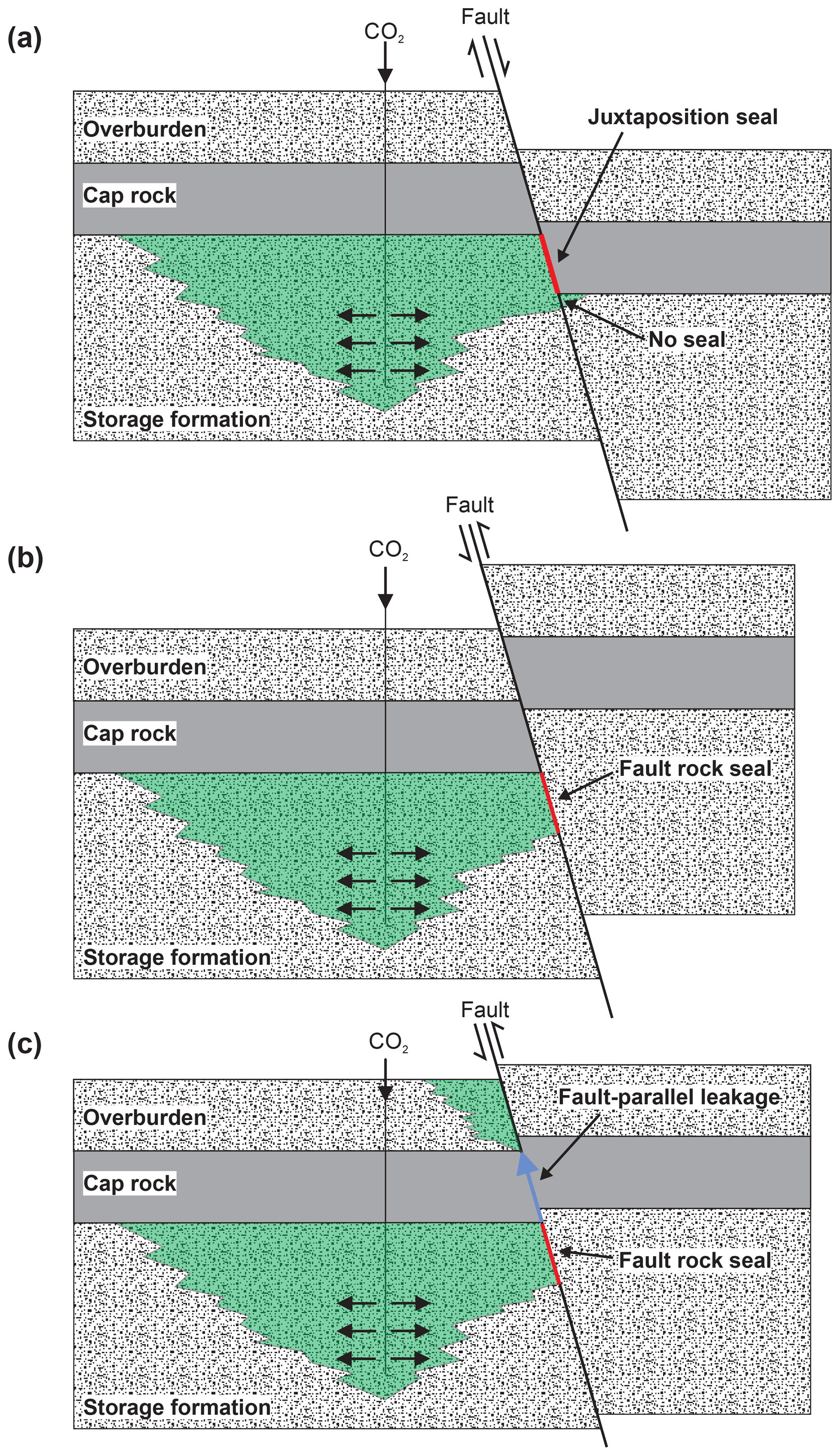
Figure 1Impact of faults on plume migration in a CO2 storage site. (a) Juxtaposition of the permeable storage formation and impermeable cap rocks generating a juxtaposition seal. (b) Impermeable fault rocks impede fluid flow within the storage formation (fault rock seal). (c) Fault-parallel, vertical migration through fracture networks bypasses the cap rock.
Whether a fault is sealing or non-sealing is dependent on the structure and composition of the rock volume affected by faulting and the mechanics of faulting (Caine et al., 1996; Aydin, 2000; Annunziatellis et al., 2008; Faulkner et al., 2010). Caine et al. (1996) describe fault zones in siliciclastic rocks defined by a fault slip surface and core and an associated damage zone, and they considered the changes in the permeability of a fault in this context. Fault damage zones and the fault cores are interpreted as having contrasting mechanical and hydraulic properties, with the fault core often being rich in phyllosilicates, which typically have low permeability, while open fractures in the damage zone can have a substantially higher permeability than the host rock (Caine et al., 1996; Faulkner and Rutter, 2001; Guglielmi et al., 2008; Cappa, 2009). Models for fault zone characterization have evolved and describe fault zones with single high-strain cores (Chester and Logan, 1986) and containing several cores (Faulkner et al., 2003), with cores and slip surfaces at the edge of the fault zone and in the middle. Perhaps to think of it simply, one model does not fit all and the heterogeneities in natural fault systems and rocks result in unique fault geometries and evolutions, albeit with similarities and semi-predictable processes.
When a fluid lighter than the pore-filling brine, such as hydrocarbons or CO2, is introduced into a reservoir, it will naturally migrate upwards due to the buoyancy effect until it encounters a flow barrier such as a cap rock or a fault. The fluid will accumulate underneath the flow barrier until capillary breakthrough or, less frequently, induced fracturing occurs due to the increase in pressure within the reservoir. The maximum vertical extent of the fluid underneath the seal before seal failure, often referred to as column height, is controlled by the fluid flow properties of the seal with regards to the fluid (Wiprut and Zoback, 2002). In the hydrocarbon industry, column heights are routinely calculated as they estimate the maximum amount of oil or gas that could be accumulated within a prospect (Downey, 1984). As the fluid flow properties of the seal may vary spatially, some uncertainty is associated with column heights, in particular when faults with their associated heterogeneities form reservoir-bounding seals. In the context of CO2 storage, column heights represent the maximum amount of CO2 that could be stored within a reservoir before migration out of the reservoir.
Evidence from outcrop studies indicates that faults play an important role for the migration of CO2 in the subsurface. Both fault-parallel migration of CO2 in fault damage zones (Annunziatellis et al., 2008; Gilfillan et al., 2011; Kampman et al., 2012; Burnside et al., 2013; Keating et al., 2013, 2014; Frery et al., 2015; Jung et al., 2015; Skurtveit et al., 2017; Bond et al., 2017; Miocic et al., 2019) and across-fault migration have been reported (Shipton et al., 2004; Dockrill and Shipton, 2010). Studies of natural analogues for CO2 storage sites have shown that if naturally occurring CO2 reservoirs fail to retain column heights of CO2 in the subsurface, this is almost exclusively due to fault leakage (Miocic et al., 2016; Roberts et al., 2017).
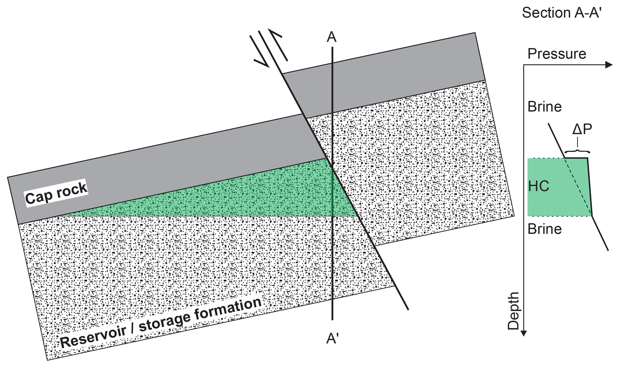
Figure 2Injection of CO2 into a faulted geological formation where the fault is sealing. The buoyancy of CO2 creates a pressure difference at the seal and fault displayed on a pressure–depth plot for the point of the diagram labelled A–A'.
In this contribution we review the main methods used to predict hydrocarbon column heights for fault-bound reservoirs as applied to hydrocarbons. Placing these into a CO2 context, we consider the implications of the assumptions used and their applicability for CO2 storage. Stochastic simulations are used to test the impact of CO2-specific uncertainties on different fault seal algorithms and how these affect the predicted CO2 column height. The results highlight the fact that fault seal parameters are poorly constrained for CO2 and can significantly change the predicted CO2 storage volume in fault-bounded reservoirs. Importantly, our results suggest that increasing amounts of phyllosilicates within the fault core, normally associated with increasing fault impermeability, may not necessarily increase the CO2 column height within a reservoir.
As they are less dense than the pore-filling brine, hydrocarbons (HCs) migrate to the top of a reservoir where they accumulate underneath a seal. The buoyancy of HCs creates a pressure difference of ΔP at the seal–reservoir interface that is proportional to the hydrocarbon plume or column height (h) and the difference in mass density between brine (ρw) and HC (ρhc):
where g is the gravitational constant, and the density of HCs is dependent on the phase (gas or oil) and the in situ pressure and temperature conditions.
The trapping of HCs within rocks is controlled by capillary forces: the interfacial tension (IFT) between HCs and the brine, the wettability of the rock–mineral surface (wetting or contact angle, θ) with respect to HCs, and the structure (size) of the pore system. Capillary pressure (Pc), the pressure difference that occurs at the interface of HCs and brine, is commonly expressed as
where Phc is the pressure of the HC, Pbrine is the pressure of the brine, and r is the pore-throat radius. Pc is inversely proportional to the pore-throat radius, and thus fine-grained rocks with small pores exhibit larger Pc and act as flow barriers to migrating HCs, leading to the accumulation of fluids underneath fine-grained seal rocks.
For HCs the wettability parameters IFT and θ vary with depth, and particularly large changes occur between surface conditions and conditions found at depths of 1000 m. IFT of oil increases from around 25 mN m−1 at very shallow conditions to around 40 mN m−1 for conditions commonly found in reservoirs at 2.5 km of depth (Yielding et al., 2010). For methane IFT is around 70 mN m−1 at surface conditions and decreases to 40 mN m−1 at subsurface conditions (Firoozabadi and Ramey, 1988; Watts, 1987). The contact angle for HCs is commonly reported as 0∘ (Vavra et al., 1992), simplifying Eq. (2) as the cosine of 0∘ is 1. However, for other fluids such as CO2, the wettability parameters IFT and θ are even more pressure and temperature dependent.
Due to the heterogeneous nature of rocks the size of pores within the sealing rock (fault rock or cap rock) varies to a certain degree, and thus two capillary pressures can be defined. The first is the capillary entry pressure (Pe), which controls the initial intrusion of the non-wetting fluid into the low-permeability rock and is controlled by the radius of the largest pore throat that is in contact with the reservoir rock. The second, which is of greater interest for column height calculations, is the capillary threshold pressure (Pth), sometimes called the capillary breakthrough pressure, at which the wetting phase in the low-permeability rock is displaced to such an extent that the percolation threshold is exceeded and a continuous flow path of the non-wetting phase forms across the pore network. The capillary threshold pressure is controlled by the smallest pore throat along the flow path, and thus Pe < Pth applies. Seal failure occurs when buoyancy pressure is larger than capillary breakthrough pressure and the maximum supported column height follows from Eqs. (1) and (2):
The ability of fault-bound reservoirs to retain significant column heights thus depends on the fault rock composition, which controls the pore-throat size (r), and the wettability parameters (IFT, θ). The composition and type of fault rocks in siliciclastic rocks are mainly influenced by (i) the composition of the wall rocks that are slipping past each other at the fault, in particular their content of fine-grained phyllosilicate clay minerals, (ii) the stress conditions at the time of faulting, and (iii) the maximum temperature that occurred in the fault zone after faulting (Yielding et al., 2010).
In clay-poor sequences (i.e. clean sandstones with less than 15 % clay), the dominant fault rock types are disaggregation zones and cataclasites (Fisher and Knipe, 1998; Sperrevik et al., 2002). Disaggregation zones form during fault slip at low confining stress during early burial and constitute grain reorganization without grain fracturing. Thus, they tend to have similar hydraulic properties as their host sandstones and do not form flow barriers (Fisher and Knipe, 2001). At deeper burial (typically > 1 km) and higher confining stresses, cataclastic processes are more significant and the resulting fractured grain fragments block the pore space, resulting in higher Pth and in permeabilities on average 1 to 2 orders of magnitude lower than the host rock (Fisher and Knipe, 2001). Additionally, quartz cementation can further lower permeabilities in both disaggregation zones and cataclasites if they are subjected to post-deformation temperatures of > 90 ∘C, which equates to > 3 km burial depths at typical geothermal gradients (Fisher et al., 2000).
In sequences with intermediate clay content (15 %–40 % phyllosilicate), fault rocks are formed by a deformation-induced mixing of generally unfractured quartz grains and clay matrix. The resulting texture creates a fault rock with a texture termed clay-matrix gouge or phyllosilicate framework fault rock (Fisher and Knipe, 1998). Due to the clay content these fault rocks generally have high Pth and low permeabilities (Gibson, 1998).
In sequences dominated by clay or shale beds (> 40 % phyllosilicate), clay- and shale-rich smears can be formed on the fault plane (Weber et al., 1978). Such smears occur during ductile deformation at depths at which the beds are not strongly consolidated and are often wedge-shaped, with the thickest smear adjacent to the source bed (Aydin and Eyal, 2002; Vrolijk et al., 2016). If faulting occurs at deeper burial depths at which the beds are lithified, shale smears can be generated by abrasional rather than ductile processes. In such cases thin shale coatings of more or less constant thickness are formed along the fault plane (Lindsay et al., 1993). Gaps within the clay and shale smears can occur at any point (Childs et al., 2007), lowering the hydrocarbon sealing capacity of the fault rock significantly.
As direct information on fault rock composition is very rare for subsurface cases, several algorithms have been developed in the past decades to estimate the probable fault rock composition at each point of the fault surface (Weber et al., 1978; Fulljames et al., 1997; Lindsay et al., 1993). The widely used shale gouge ratio (SGR) algorithm takes the average clay content of beds that slipped past any point (based on fault throw) (Yielding et al., 1997):
SGR can be used as an estimate of fault rock composition; with high SGRs (> 40 %–50 %) the fault rock is assumed to be dominated by clay smears, while low SGRs (< 15 %–20 %) indicate that the fault rock is likely to be disaggregation zones or cataclasites (Yielding et al., 2010). The SGR algorithm, similar to other algorithms like the shale smear factor (Lindsay et al., 1993), the clay smear potential (Fulljames et al., 1997), and the probabilistic shale smear factor (Childs et al., 2007), which all use a combination of throw and clay bed distribution or thickness to predict the effects of clay smears, does not consider the detailed fault rock distribution and fault zone complexity observed on outcrops or at the centimetre and sub-centimetre scale (Faulkner et al., 2010; Schmatz et al., 2010). It has, however, been successfully used during the last 2 decades to predict hydrocarbon fault seals in the subsurface (Manzocchi et al., 2010; Yielding, 2012).
Two different approaches to link SGR and fault rock composition estimation with fault seal prediction parameters such as capillary threshold pressure have been developed over the years: (1) using known sealing faults to constrain relationships between SGR and HC column height and/or across fault pressure differences (Bretan et al., 2003; Yielding et al., 2010) and (2) measuring the capillary threshold pressures and clay content of micro-faults and correlating these with SGR, assuming that SGR is equivalent to the clay content of the fault rock (Sperrevik et al., 2002). The first approach has been fine-tuned with datasets from sedimentary basins around the world, while equations linking capillary pressure and clay content in the second approach are derived from best-fit relationships of samples mainly from the North Sea.
with C=0.5 for burial depths of less than 3 km, C=0.25 for burial depths of 3.0–3.5 km, and C=0 for burial depths greater than 3.5 km.
(for burial depths of less than 3 km)
for burial depths of more than 3.5 km
PthS is the Hg–air fault rock threshold pressure and kf the fault rock permeability:
where zmax is the maximum burial depth and zf is the depth at the time of faulting.
These three algorithms (Eqs. 5–9) are widely applied to predict fault seals. In combination with Eq. (3) they can be used to calculate maximum fluid-column heights. While the Bretan et al. (2003) algorithm (Eq. 5) assumes an exponential correlation between the fault rock clay content (FRCC) and the capillary threshold pressure, Yielding's (2012) algorithm (Eqs. 6 and 7) is based on the assumption of a linear correlation between these variables. The Sperrevik et al. (2002) (Eqs. 8 and 9) algorithm also assumes an exponential relationship but tends to predict lower capillary threshold pressures than the Bretan et al. (2003) algorithm (Fig. 3). Note that reported capillary pressures are typically measured in Hg–air–rock systems, which are often used to experimentally derive capillary pressures. In order to convert them to fluid–brine–rock systems, the following equation is used:
where P is capillary pressure, IFT interfacial tension, and θ contact angle; indices indicate the fluid system. This equation highlights the fact that uncertainties of the wettability parameters can strongly influence capillary breakthrough pressures derived from mercury injection experiments (Heath et al., 2012; Lahann et al., 2014; Busch and Amann-Hildenbrand, 2013). Thus, the results of the three algorithms are not necessarily directly comparable. Here we apply these equations (Eqs. 5–10) to a CO2 storage framework to test their veracity and analyse the revealed associated uncertainties.
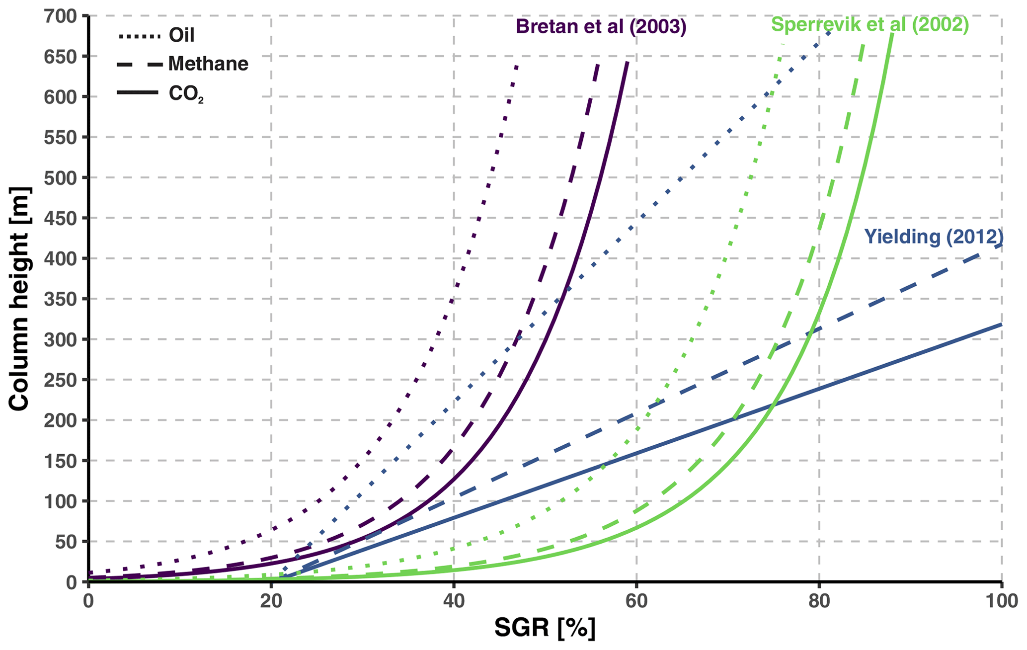
Figure 3Plot of SGR content of fault rocks and the resulting column heights for the algorithms of Bretan et al. (2003), Sperrevik et al. (2002), and Yielding (2012) for different fluid types for a reservoir at a depth of 1000 m. Assumes contact angles of 50∘ for CO2 and 0∘ for methane and oil, with interfacial tensions of 38 mN m−1 for the CO2–brine–rock system, 60 mN m−1 for the methane–brine–rock system, and 30 mN m−1 for the oil–brine–rock system. Fluid densities are 515 kg m−3 for CO2, 75 kg m−3 for methane, 800 kg m−3 for oil, and 1035 kg m−3 for brine.
In contrast to the HC–brine–rock system, the wettability of the CO2–brine–rock system is strongly controlled by temperature, pressure, and mineralogy (Iglauer et al., 2015b; Zhou et al., 2017). As a result, a fault seal that supports a certain hydrocarbon column height may not necessarily support a similar amount of CO2 (Naylor et al., 2011). This highlights the need to have a good understanding of the CO2 wettability in the subsurface in order to establish the security of carbon storage sites.
The IFT of the CO2–brine system is temperature, pressure, and salinity dependent. It decreases from ∼72 to 25 mN m−1 as pressure increases from atmospheric to 6.4 MPa and plateaus at around 25±5 mN m−1 for supercritical CO2 conditions and deionized water (Kvamme et al., 2007; Chiquet et al., 2007; Espinoza and Santamarina, 2010). High salinity levels, as often found in the brine filling deep saline formations, can increase the interfacial tension by up to 10 mN m−1 (Espinoza and Santamarina, 2010; Saraji et al., 2014). Additionally, CO2 dissolved in the brine may decrease IFT (Nomeli and Riaz, 2017), as may impurities such as CH4 or SO2 (Ren et al., 2000; Saraji et al., 2014). Thus, for the conditions most likely for storage reservoirs – supercritical CO2 at depths greater than 1200 m with saline brine (Miocic et al., 2016) – CO2–brine IFT will be of the order of 35±5 mN m−1 (Fig. 4), similar to the range recently illustrated by Iglauer (2018).
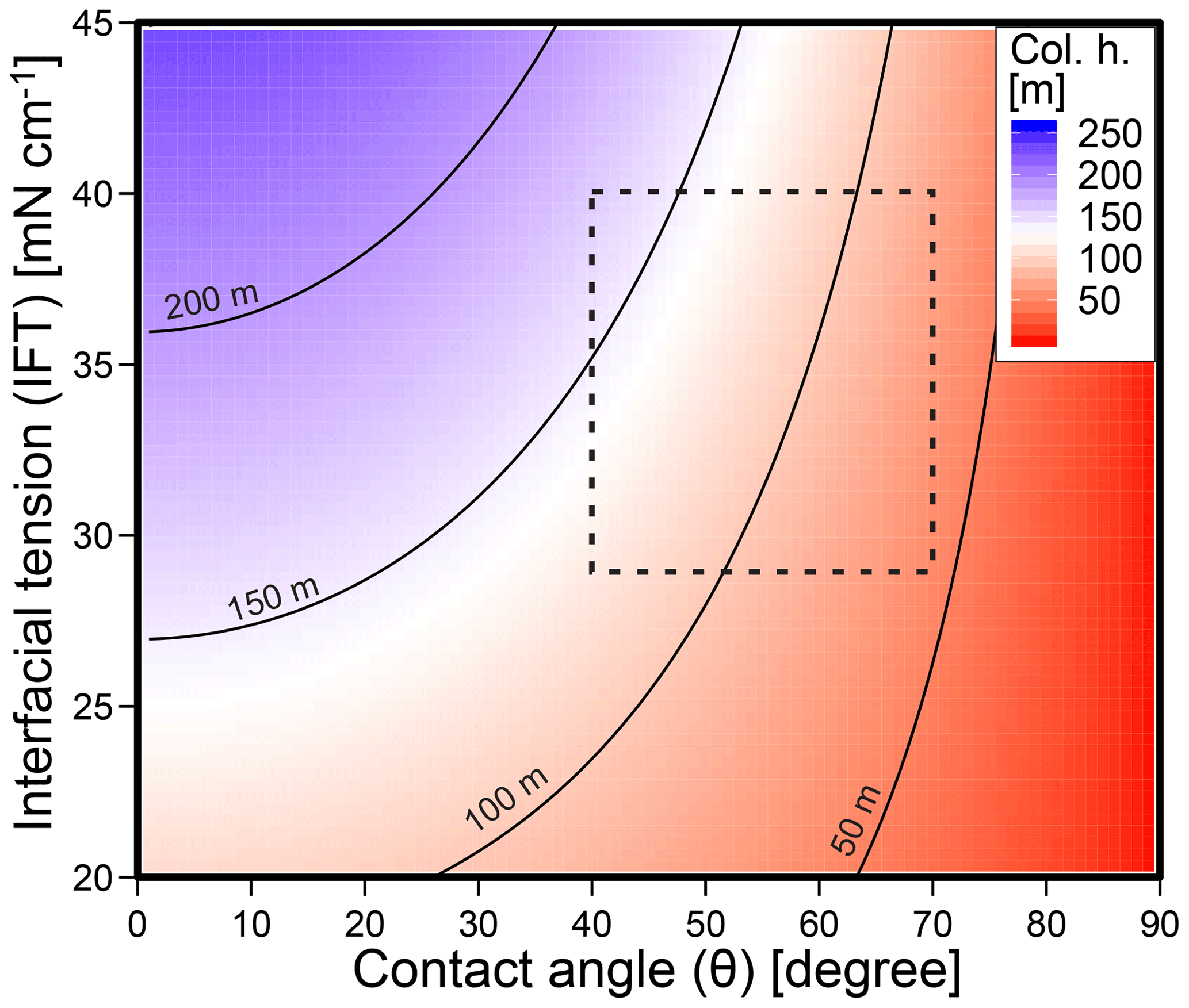
Figure 4Figure showing the influence of contact angle (θ) and interfacial tension (IFT) on supported CO2 column height. Black lines are contours at 50 m intervals. The full range of IFT and θ shown here has been reported for CO2–brine–rock systems; the dashed rectangle indicates conditions likely for geological storage. Column height calculated using Eqs. (1) and (2) with a pore-throat diameter of 100 nm, a typical value for organic-poor shales (Dong et al., 2017), and a CO2 density of 630 kg m−3, correlating to a depth of about 1500 m.
The contact angle formed by the CO2–brine interface on mineral surfaces varies strongly and is dependent on pressure and temperature conditions, mineral type, the presence of organic matter, and the wetting phase (Sarmadivaleh et al., 2015; Espinoza and Santamarina, 2017). On water-wet minerals, the contact angle (θ) is about 40∘ on amorphous silica and calcite surfaces, θ ∼40 to 85∘ on mica, θ ∼50 to 120∘ on coal, and θ ∼8 to 30∘ on organic shale surfaces, while on oil-wet amorphous silica θ ∼85 to 95∘ (Chi et al., 1988; Chiquet et al., 2007; Chalbaud et al., 2009; Espinoza and Santamarina, 2010, 2017; Iglauer et al., 2015b; Arif et al., 2016; Guiltinan et al., 2017). With pressure rising from 10 to 15 MPa, θ increases up to 10∘ on quartz surfaces, while an increase in temperature from 50 to 70 ∘C at 10 MPa leads to an increase in θ of 15∘ (Sarmadivaleh et al., 2015). The CO2 state also seems to influence the contact angle in oil-wet pores with θgas < θsc (Li and Fan, 2015). Additionally, the wettability of rocks may shift towards more hydrophobic the longer it is exposed to a CO2–brine mixture (Wang and Tokunaga, 2015). From the experimental data available for the conditions most likely for storage reservoirs, θ in water-wet conditions will range from ∼40∘ for quartz-dominated rocks to ∼70∘ for an organic-mica-rich rock (Fig. 4), with higher values likely for deeper reservoirs (Iglauer, 2018).
A general issue with the wettability data available is that most experiments are done on single, very pure, and cleaned mineral surfaces and that data on the wettability of “real” subsurface rock–brine–CO2 systems are very limited. Indeed, for potential cap rock and reservoir rock lithologies such as dolomite, anhydrite, halite, mudrock, clays, or fault rocks no data for subsurface conditions exist (Iglauer et al., 2015b). Recent developments for characterizing microscale variations of wettability in low-permeability rocks may improve knowledge in the future (Deglint et al., 2017). The wettability of fault rocks has to our knowledge not been studied experimentally yet but, as illustrated by the influence of mineralogy on contact angles, will depend on fault rock composition.
As a wide range of IFT and CA values seem possible at the CO2–seal interface at the subsurface conditions likely for carbon storage sites, the sealing potential of faults for CO2 and the conditions under which faults will form seals to CO2 flow are unclear.
In order to better understand the impact of the uncertainties of interfacial tension, contact angle (wettability), and fault rock composition (FRC) described on commonly used fault seal algorithms when applied to CO2, we run stochastic models in which the input parameters follow probability distributions (i.e. have uncertainties associated). We use a Markov chain Monte Carlo (MCMO) approach, which samples the probability distributions of input parameters (Gilks et al., 1996), to statistically analyse the effect of uncertainties in wettability and fault rock clay content (based on SGR) on the amount of CO2 that can be securely stored in a fault-bound reservoir. The input parameters, which are all treated as independent, are derived from the published data described: empirical values from Iglauer (2018) and experimental from Botto et al. (2017), Iglauer et al. (2015b), and Saraji et al. (2014). These parameters follow a normal distribution described by the mean and the standard deviation (σ) as seen in Table 1 and are randomly sampled 20 000 times for each model run. Capillary threshold pressures for fault seals are calculated by using Eqs. (5) to (9) (the algorithms by Bretan et al., 2003, Yielding, 2010, and Sperrevik et al., 2002); these are then converted to the CO2–brine system using Eq. (10), and subsequently column heights are calculated assuming a pore-throat size of 100 nm (Eq. 3). Note that Eqs. (5) to (7) result in maximum column heights (or minimal wettability), while Eqs. (8)–(9) give an average column height. The resulting column heights also follow a probability distribution (Table 2).
Table 1Table listing the input parameters for the MCMO modelling. Reservoir A and B refer to the two theoretical reservoirs described in the text, the approach refers to the algorithm used (see text), and the model indicates whether uncertainties in wettability parameters (Wet), fault rock composition (FRC), and/or combined uncertainties (Comb) are modelled. IFT is the interfacial tension (mN m−1), CA the contact angle, SGR the shale gouge ratio as a parameter for fault rock composition, and PTS the pore-throat size in nanometres; σ is the standard deviation and describes the shape of the input normal distribution.
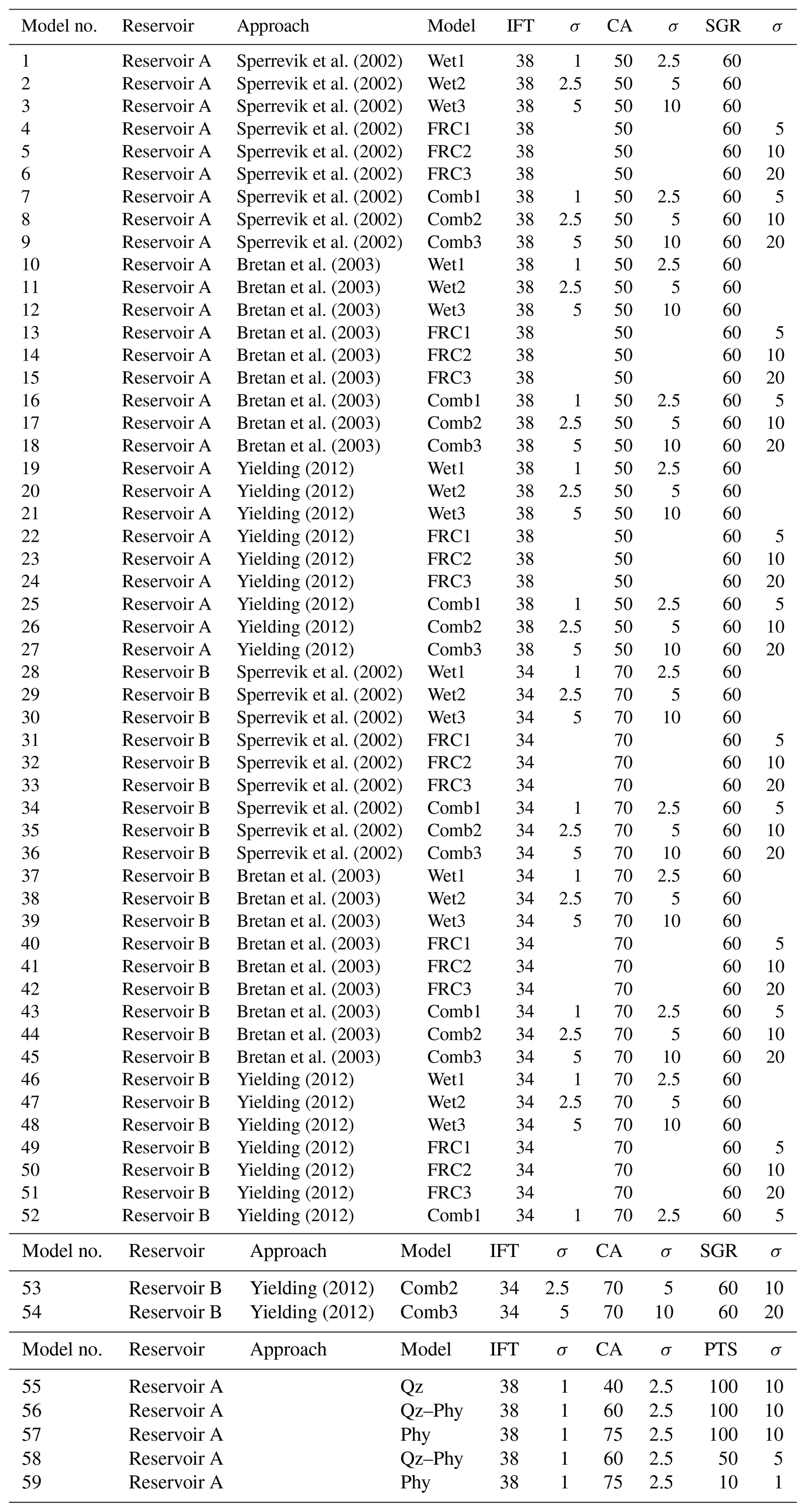
Two theoretical cases are modelled: reservoir A is located at 1000 m of depth with a temperature of 45 ∘C, a pressure of 10.2 MPa, and a resultant CO2 density of 515 Kg m−3. Reservoir B is located at a depth of 1800 m, has a temperature of 69 ∘C, a pressure of 18.36 MPa, and a resultant CO2 density of 617 Kg m−3. Both reservoirs have a brine density of 1035 Kg m−3, a maximum burial depth of 2000 m, and a faulting depth of 1500 m. The normal distributions of the input parameters (FRC (SGR) and wettability of the fault rock (CA, IFT)) for the MCMO modelling are listed in Table 1. IFTs of 38 and 34 mN m−1 and CAs of 50 and 70∘ are used as mean wettability for the MCMO models of reservoir A and reservoir B, respectively, based on the IFT–depth and CA–depth relationships of Iglauer (2018). For models in which the approaches by Bretan et al. (2003) and Yielding (2010) are used, these correspond to the mean least wettability. For each of the reservoirs 27 models were run with 20 000 iterations each, 9 models for each of the approaches that link SGR to fault rock threshold pressure (Eqs. 5 to 9). Of these nine models three simulate varying uncertainties in CA and IFT of the fault rock (models Wet1 to Wet3), three have varying uncertainties in FRC (models FRC1 to FRC3), and three models calculate column heights based on uncertainties of FRC and fault rock wettability (models Comb1 to Comb3).
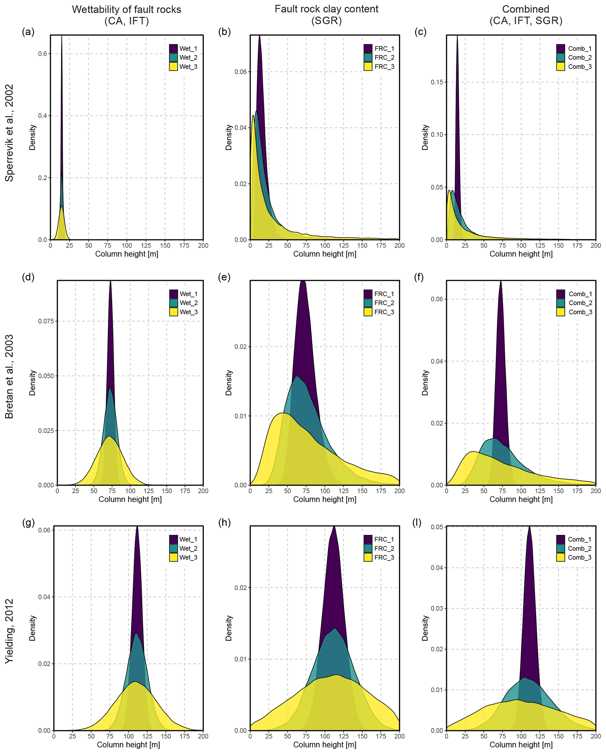
Figure 5Density distribution of column heights of models for reservoir A (models 1 to 27). (a, d, g) The impact of uncertainties in fault rock wettability, (b, e, h) the impact of uncertainties in fault rock clay content (SGR), and (c, f, i) the impact of combined uncertainties on column heights. Each row uses a different approach to link fault rock composition to threshold pressure. Uncertainty increases from dark- to light-coloured models (Table 1). For all models N=20 000.
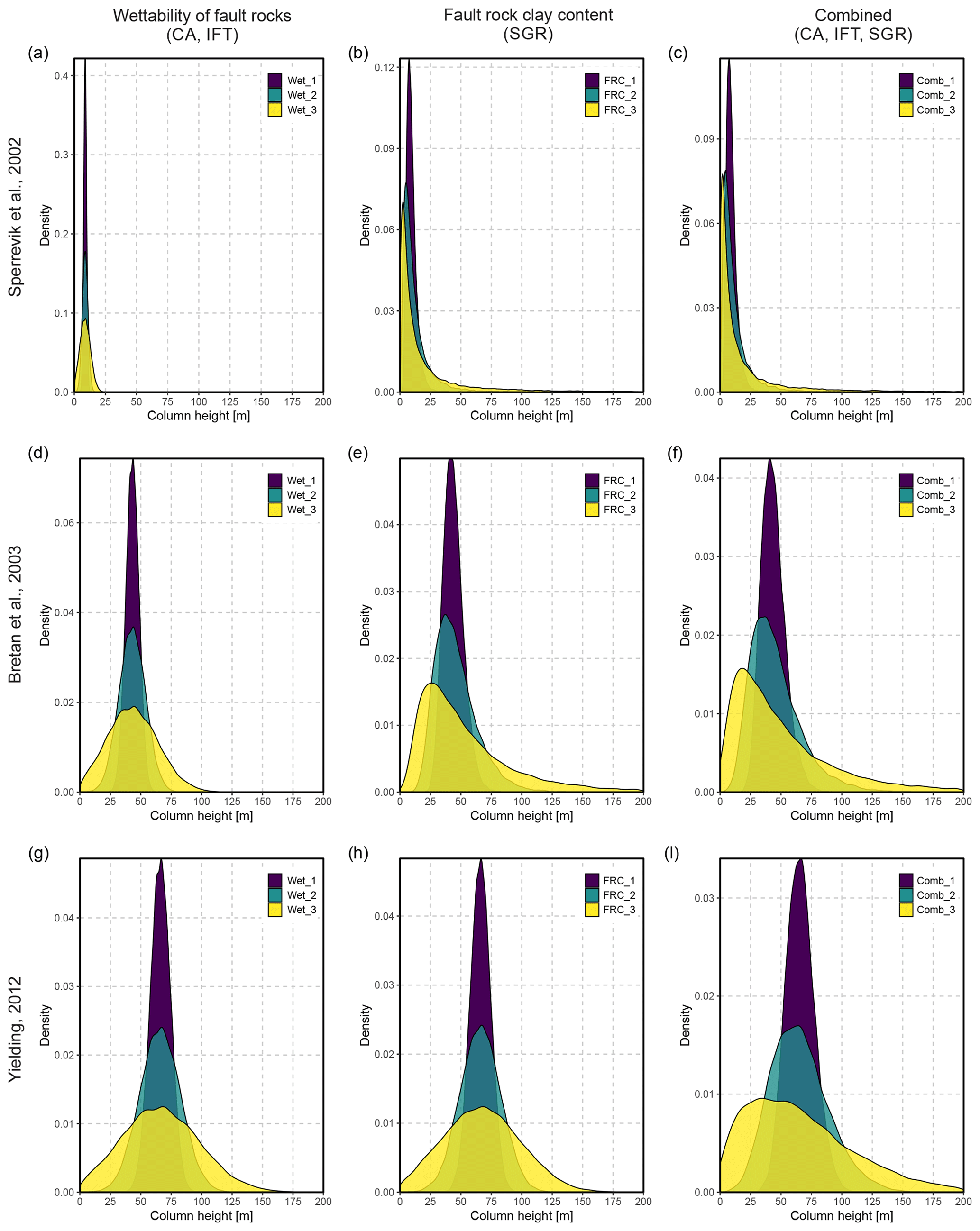
Figure 6Density distribution of column heights of models for reservoir B (models 28 to 54). (a, d, g) The impact of uncertainties in fault rock wettability, (b, e, h) the impact of uncertainties in fault rock clay content (SGR), and (c, f, i) the impact of combined uncertainties on column heights. Each row uses a different approach to link fault rock composition to threshold pressure. Uncertainty increases from dark- to light-coloured models (Table 1). For all models N=20 000.
Five additional models investigate the impact FRC (and associated uncertainties) and the size of the pore throat have on supported column heights for reservoir A using Eq. (3). Model nos. 55 to 57 simulate a quartz-rich fault rock (95 % of IFT within 38±2 mN m−1, 95 % of CA within 40±5∘), a quartz–phyllosilicate mixture (95 % of IFT within 38±2 mN m−1, 95 % of CA within 60±5∘), and a phyllosilicate-rich fault rock (95 % of IFT within 35±2 mN m−1, 95 % of CA within 75±5∘) with pore-throat sizes of 100±10 nm (95 % interval). Model nos. 58 and 59 adopt pore-throat sizes reported by Gibson (1998) for outcrop and core samples of fault zones: the pore-throat diameters of the quartz–phyllosilicate mixture of model no. 58 are intermediate (95 % within 50±5 nm), and for the phyllosilicate-rich fault rock of model no. 57 they are low (95 % within 10±1 nm).
The results of the MCMO models highlight the differences between the three approaches that link FRC to fault rock threshold pressure with the approach of Sperrevik et al. (2002), generally resulting in lower column heights than the approaches of Bretan et al. (2003) and Yielding (2012) for both reservoir A and B (Table 2, Figs. 5 and 6). Uncertainties in the wettability of fault rocks (CA, IFT) have less of an impact on the supported column height distributions than uncertainties in FRC.
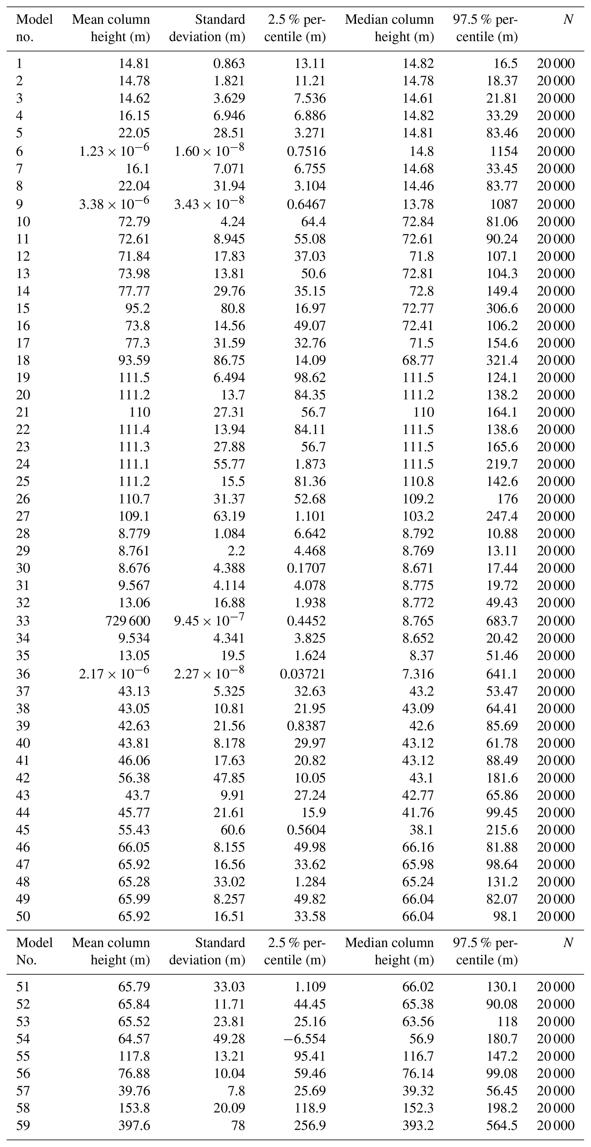
For reservoir A, the models which are used to investigate the impact of uncertainties in wettability (Wet1–Wet3) have column heights ranging from 14.8±0.9 to 14.6±3.6 m (after Sperrevik et al., 2002), from 73±4 to 72±18 m (after Bretan et al., 2003), and from 111±6 to 110±27 m (after Yielding, 2012). Models which simulate uncertainties in FRC in the same reservoir have column heights ranging from 16±7 m, from 74±14 to 95±80 m, and from 111±14 to 111±55 m for the three different approaches, respectively. Models which combine the uncertainties of fault rock wettability and FRC (Comb1–Comb3) have an even wider spread in column height distributions (Fig. 5c, f, i). For reservoir B, all models show a similar pattern to those of reservoir A (Fig. 6); however, the mean supported column heights are only about 60 % of those for reservoir A due to the differences in fault rock wettability parameters (Tables 1, 2). This illustrates the fact that conditions in deeper reservoirs may lead to lower column heights.
The results of models 55 to 59 (Fig. 7) illustrate the impact of both pore-throat size and FRC on the supported column height. For conditions similar to reservoir A, a quartz-rich fault rock with a pore-throat size of 100 nm (model 55) can support a column height of 118±13 m, while a mixture of quartz and phyllosilicates with the same pore-throat size (model 56) is likely to support 77±10 m, and a phyllosilicate-rich fault rock (model 57) can support a column height of 40±8 m. For a smaller pore-throat size of 50 nm a mixture of quartz and phyllosilicates (model 58) can support a column height of 153±20 m, and a phyllosilicate-rich fault rock with a pore-throat size of 10 nm can on average support a column height of 398±78 m. Note that the tails of the model distributions increase from model 55 to model 59. Based on the change in pore-throat sizes alone, the column heights of model 59 should be 1 order of magnitude larger than those of model 55.
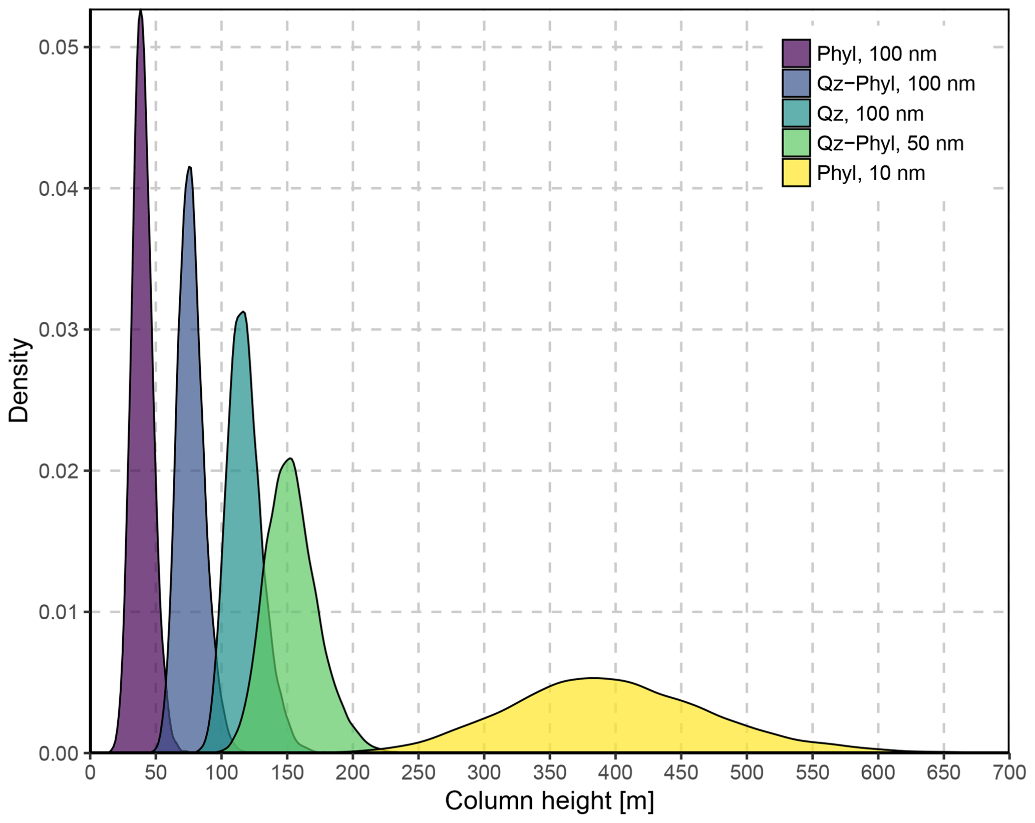
Figure 7The density distribution of column heights of models 55 to 59 illustrates the role of fault rock composition and pore-throat size on supported column heights. If the pore-throat size is the same, phyllosilicate-rich fault rocks can only support low column heights compared to quartz-rich fault rocks. If the pore size decreases with increasing phyllosilicate content, the column height increases with increasing phyllosilicate content. However, the increase in column heights is significantly less than the 1 order of magnitude expected due to the change in pore-throat size. This is due to CO2 wettability depending on fault rock composition, which results in phyllosilicate-rich fault rocks supporting a lower column than quartz-rich fault rocks with a similar pore throat. Column height is calculated using Eq. (3) and a CO2 density of 515 kg m−3 (as reservoir A). For all five models N=20 000.
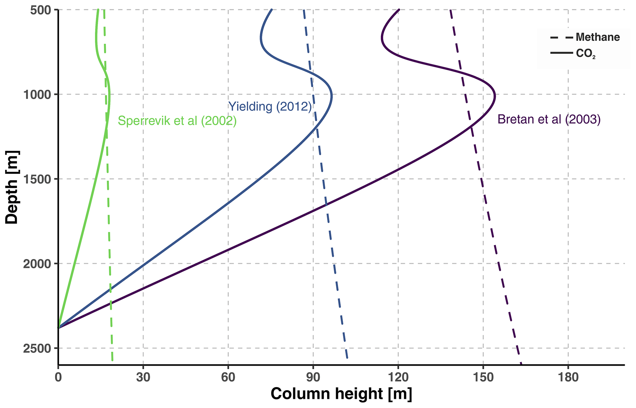
Figure 8Supported column heights of a fault with a phyllosilicate-rich fault rock (SGR = 40) depending on the depth of the fault and the trapped fluid. For CO2 the column height decreases with depth (after an optimum at ∼1000 m of depth), while methane column heights increase with depth. Based on depth–wettability relationships for CO2 by Iglauer (2018).
The results of the stochastic modelling illustrate that even small uncertainties in fault seal parameters can introduce significant variations and spread in the amount of CO2 predicted to be securely stored within a fault-bound siliciclastic reservoir. In particular, uncertainties in fault rock composition result in a wider range of possible column heights when compared to uncertainties of CO2–brine–rock wettability. The outcomes also illustrate large differences between the algorithms used to calculate column heights. Additionally, phyllosilicate-rich fault rocks can support lower CO2 column heights than quartz-rich fault rocks if a constant pore-throat radius is assumed.
The use of SGR as a proxy for fault rock composition, as in our study, is widely accepted and commonly applied for hydrocarbon reservoirs (Fristad et al., 1997; Lyon et al., 2005). The algorithm linking SGR to fault zone threshold pressure and column height is a critical step in fault seal studies, and our results show that different algorithms (Eqs. 5–9) predict different CO2 column heights. This is in line with other works comparing the three algorithms (Bretan, 2016) and is due to the sensitivity of the Sperrevik algorithm to geological history (faulting depth and maximum burial). The algorithm has been developed from samples of North Sea cores from depths ranging from 2000 to 4500 m. The approaches by Bretan et al. (2003) and Yielding (2012) are both used to calculate the maximum threshold pressure, and the approach by Sperrevik et al. (2002) gives an average threshold pressure. Thus, when used for a carbon storage capacity assessment, the column heights calculated with the algorithms of Bretan et al. (2003) and Yielding (2012) would illustrate the maximum potential storage capacity, while the column heights resulting from the Sperrevik et al. (2002) algorithm would likely represent average capacities.
The high impact of SGR on column heights is predictable as SGR is a proxy for the amount of phyllosilicates incorporated into the fault rock, and our results are in line with other work which highlights the fact that good prediction of fault rock composition is crucial for hydrocarbon column height prediction (Fisher and Knipe, 2001; Yielding et al., 2010). When SGR is used for predicting fault seals in a hydrocarbon context, higher SGR values coincide with higher contained column heights, as high-SGR-value fault rocks have a higher phyllosilicate content (and hence smaller pore-throat radii). Our results show that for a CO2 fluid the decrease in pore-throat size due to a higher phyllosilicate content results in lower column heights than anticipated. The fact that for constant pore-throat sizes phyllosilicate-rich fault rocks can only support lower column heights than quartz-rich fault rocks (Fig. 7) highlights the difference between the wettability of the CO2–brine–rock system and the wettability of the HC–brine–rock system at subsurface conditions. Phyllosilicate minerals have contact angles of up to 85∘, while quartz has a contact angle around 40∘ (Espinoza and Santamarina, 2017; Iglauer et al., 2015a). Increasing the content of phyllosilicates in the fault rock (increasing FRCC and SGR) effectively increases the contact angle, which directly reduces the capillary threshold pressure as the cosine of the contact angles approaches zero (Eq. 2). This indicates that an increase in phyllosilicates in the fault rock may not increase the amount CO2 that can be retained by the fault to the same degree as for hydrocarbons. This calls into question whether algorithms such as SGR, which assume that higher phyllosilicate content in fault gouges equal higher sealing properties, can be used to effectively predict CO2 fault seals. We suggest that introducing pore-throat sizes into fault seal algorithms may result in more reasonable column height predictions for CO2 systems.
The results of our stochastic models also illustrate the impact of depth on the wettability of the CO2–brine–rock system, with the deeper faulted reservoir scenario (at a depth of 1800 m) holding significantly lower column heights than the shallower reservoir (depth of 1000 m). This is in contrast to fault seals for hydrocarbons for which faults can retain higher fluid columns for similar SGR values in deeper reservoirs (Yielding, 2012). The influence of pressure on the sealing capacity of fault rocks for CO2 has direct implications for the selection of carbon storage sites, with shallow reservoirs being able to retain a higher column of CO2 than deeper reservoirs (Fig. 8). Note that minimum CO2 storage site depths are around 1000 m and are governed by the CO2 state and density (Miocic et al., 2016).
Non-sealing faults are often undesired in a hydrocarbon exploration context, but this is not necessarily true in the case of carbon storage sites. Here, sealing faults may actually reduce the amount of CO2 that can be safely stored within a reservoir as the lateral migration of the CO2 plume is hindered and pressure build-up may occur (Chiaramonte et al., 2015; Vilarrasa et al., 2017). If fault rocks that are sealing for hydrocarbons are not necessarily sealing for CO2, as the results of our study suggest, faulted abandoned hydrocarbon reservoirs could form good carbon storage sites as long as no vertical migration of CO2 along the fault occurs.
Fault seal modelling is associated with significant uncertainties arising from the limited subsurface data, resolution of seismic data, faulting mechanics and fault zone structure, spatial and temporal variations, and overall limitations of the scalability of observations. Nonetheless, several models to estimate the sealing properties of faults have been developed and successfully used to predict hydrocarbon column heights. However, for the fault seal modelling of CO2 reservoirs the wettability of the CO2–brine–rock system introduces additional uncertainties and reduces the amount of CO2 that can be securely stored within a reservoir compared to hydrocarbons.
In this study uncertainties in fault rock composition, as well as uncertainties of how CO2 fluid–rock wettability properties of the reservoir change with depth, have a stronger impact on CO2 column heights than uncertainties in wettability. Importantly, a higher phyllosilicate content within the fault rock at a given pore-throat size, which is commonly assumed to increase the threshold pressure, may reduce the threshold pressure due to increased CO2-wetting behaviour with such minerals. In particular, deep reservoirs and high pressures seem to lead to lower column heights when compared to the equivalent predicted hydrocarbon column height.
To ensure CO2 storage security, appropriate site characterization for storage sites is critical. Faults of all scales must be identified and their seal potential modelled with a range of uncertainties, including the fault rock composition and wettability. During storage operations fault seal potential predictions could be refined by high-resolution monitoring and the development of databases similar to those used (Bretan et al., 2003; Yielding et al., 2010) to predicted hydrocarbon column heights. While fault seals may impact storage capacities, it should be kept in mind that lateral migration through non-sealing faults can increase storage capacity.
Model code is available from the corresponding author upon request.
JMM and GJ designed the project with input from CEB. JMM developed the model code and performed the MCMO simulations. The paper was written by JMM with contributions from both GJ and CEB.
The authors declare that they have no conflict of interest.
This article is part of the special issue “Understanding the unknowns: the impact of uncertainty in the geosciences”. It is not associated with a conference.
This research has been partly supported by the European Commission PANACEA project (grant no. 282900).
This paper was edited by Lucia Perez-Diaz and reviewed by Katriona Edlmann and Graham Yielding.
Allan, U. S.: Model for hydrocarbon migration and entrapment within faulted structures, AAPG Bull., 73, 803–811, 1989.
Aminu, M. D., Nabavi, S. A., Rochelle, C. A., and Manovic, V.: A review of developments in carbon dioxide storage, Appl. Energ., 208, 1389–1419, https://doi.org/10.1016/j.apenergy.2017.09.015, 2017.
Annunziatellis, A., Beaubien, S. E., Bigi, S., Ciotoli, G., Coltella, M., and Lombardi, S.: Gas migration along fault systems and through the vadose zone in the Latera caldera (central Italy): Implications for CO2 geological storage, Int. J. Greenh. Gas Con., 2, 353–372, https://doi.org/10.1016/j.ijggc.2008.02.003, 2008.
Arif, M., Al-Yaseri, A. Z., Barifcani, A., Lebedev, M., and Iglauer, S.: Impact of pressure and temperature on CO2–brine–mica contact angles and CO2–brine interfacial tension: Implications for carbon geo-sequestration, J. Colloid Interface Sci., 462, 208–215, https://doi.org/10.1016/j.jcis.2015.09.076, 2016.
Aydin, A.: Fractures, faults, and hydrocarbon entrapment, migration and flow, Mar. Pet. Geol., 17, 797–814, https://doi.org/10.1016/S0264-8172(00)00020-9, 2000.
Aydin, A. and Eyal, Y.: Anatomy of a Normal Fault with Shale Smear: Implications for Fault Seal, AAPG Bull., 86, 1367–1381, 2002.
Barton, C. A., Zoback, M. D., and Moos, D.: Fluid flow along potentially active faults in crystalline rock, Geology, 23, 683–686, https://doi.org/10.1130/0091-7613(1995)023<0683:FFAPAF>2.3.CO;2, 1995.
Bense, V. F., Gleeson, T., Loveless, S. E., Bour, O., and Scibek, J.: Fault zone hydrogeology, Earth-Sci. Rev., 127, 171–192, https://doi.org/10.1016/j.earscirev.2013.09.008, 2013.
Benson, S. M. and Cole, D. R.: CO2 Sequestration in Deep Sedimentary Formations, Elements, 4, 325–331, https://doi.org/10.2113/gselements.4.5.325, 2008.
Bjørlykke, K.: Fluid flow in sedimentary basins, Sediment. Geol., 86, 137–158, https://doi.org/10.1016/0037-0738(93)90137-T, 1993.
Bond, C. E., Kremer, Y., Johnson, G., Hicks, N., Lister, R., Jones, D. G., Haszeldine, R. S., Saunders, I., Gilfillan, S. M. V., Shipton, Z. K., and Pearce, J.: The physical characteristics of a CO2 seeping fault: The implications of fracture permeability for carbon capture and storage integrity, Int. J. Greenh. Gas Con., 61, 49–60, https://doi.org/10.1016/j.ijggc.2017.01.015, 2017.
Botto, J., Fuchs, S. J., Fouke, B. W., Clarens, A. F., Freiburg, J. T., Berger, P. M., and Werth, C. J.: Effects of Mineral Surface Properties on Supercritical CO2 Wettability in a Siliciclastic Reservoir, Energy Fuels, 31, 5275–5285, https://doi.org/10.1021/acs.energyfuels.6b03336, 2017.
Bretan, P.: Trap Analysis: an automated approach for deriving column height predictions in fault-bounded traps, Petrol. Geosci., 23, 56–69, https://doi.org/10.1144/10.44petgeo2016-022, 2016.
Bretan, P., Yielding, G., and Jones, H.: Using calibrated shale gouge ratio to estimate hydrocarbon column heights, AAPG Bull., 87, 397–413, https://doi.org/10.1306/08010201128, 2003.
Burnside, N. M., Shipton, Z. K., Dockrill, B., and Ellam, R. M.: Man-made versus natural CO2 leakage: A 400 k.y. history of an analogue for engineered geological storage of CO2, Geology, 41, 471–474, https://doi.org/10.1130/G33738.1, 2013.
Busch, A. and Amann-Hildenbrand, A.: Predicting capillarity of mudrocks, Mar. Pet. Geol., 45, 208–223, https://doi.org/10.1016/j.marpetgeo.2013.05.005, 2013.
Caine, J. S., Evans, J. P., and Forster, C. B.: Fault zone architecture and permeability structure, Geology, 24, 1025–1028, 1996.
Cappa, F.: Modelling fluid transfer and slip in a fault zone when integrating heterogeneous hydromechanical characteristics in its internal structure, Geophys. J. Int., 178, 1357–1362, https://doi.org/10.1111/j.1365-246X.2009.04291.x, 2009.
Chalbaud, C., Robin, M., Lombard, J.-M., Martin, F., Egermann, P., and Bertin, H.: Interfacial tension measurements and wettability evaluation for geological CO2 storage, Adv. Water Resour., 32, 98–109, https://doi.org/10.1016/j.advwatres.2008.10.012, 2009.
Chester, F. M. and Logan, J. M.: Implications for mechanical properties of brittle faults from observations of the Punchbowl fault zone, California, Pure Appl. Geophys., 124, 79–106, https://doi.org/10.1007/BF00875720, 1986.
Chi, S. M., Morsi, B. I., Klinzing, G. E., and Chiang, S. H.: Study of interfacial properties in the liquid carbon dioxide-water-coal system, Energy Fuels, 2, 141–145, https://doi.org/10.1021/ef00008a007, 1988.
Chiaramonte, L., Johnson, S., and White, J. A.: Preliminary Geomechanical Analysis of CO2 Injection At Snøhvit, Norway, in: ARMA-11-441, American Rock Mechanics Association, ARMA, San Francisco, 2011.
Chiaramonte, L., White, J. A., and Trainor-Guitton, W.: Probabilistic geomechanical analysis of compartmentalization at the Snøhvit CO2 sequestration project, J. Geophys. Res.-Sol. Ea., 120, 2014JB011376, https://doi.org/10.1002/2014JB011376, 2015.
Childs, C., Walsh, J. J., Manzocchi, T., Strand, J., Nicol, A., Tomasso, M., Schöpfer, M. P. J., and Aplin, A. C.: Definition of a fault permeability predictor from outcrop studies of a faulted turbidite sequence, Taranaki, New Zealand, Geol. Soc. London Spec. Pubs., 292, 235–258, https://doi.org/10.1144/SP292.14, 2007.
Chiquet, P., Daridon, J.-L., Broseta, D., and Thibeau, S.: CO2/water interfacial tensions under pressure and temperature conditions of CO2 geological storage, Energ. Convers. Manage., 48, 736–744, https://doi.org/10.1016/j.enconman.2006.09.011, 2007.
Deglint, H. J., Clarkson, C. R., DeBuhr, C., and Ghanizadeh, A.: Live Imaging of Micro-Wettability Experiments Performed for Low-Permeability Oil Reservoirs, Sci. Rep., 7, 4347, https://doi.org/10.1038/s41598-017-04239-x, 2017.
Dockrill, B. and Shipton, Z. K.: Structural controls on leakage from a natural CO2 geologic storage site: Central Utah, U.S.A., J. Struct. Geol., 32, 1768–1782, https://doi.org/10.1016/j.jsg.2010.01.007, 2010.
Dong, T., Harris, N. B., Ayranci, K., Twemlow, C. E., and Nassichuk, B. R.: The impact of composition on pore throat size and permeability in high maturity shales: Middle and Upper Devonian Horn River Group, northeastern British Columbia, Canada, Mar. Pet. Geol., 81, 220–236, https://doi.org/10.1016/j.marpetgeo.2017.01.011, 2017.
Downey, M. W.: Evaluating seals for hydrocarbon accumulations, AAPG Bull., 68, 1752–1763, 1984.
Eichhubl, P., Davatz, N. C., and Becker, S. P.: Structural and diagenetic control of fluid migration and cementation along the Moab fault, Utah, AAPG Bull., 93, 653–681, https://doi.org/10.1306/02180908080, 2009.
Espinoza, D. N. and Santamarina, J. C.: Water-CO2-mineral systems: Interfacial tension, contact angle, and diffusion – Implications to CO2 geological storage, Water Resour. Res., 46, W07537, https://doi.org/10.1029/2009WR008634, 2010.
Espinoza, D. N. and Santamarina, J. C.: CO2 breakthrough – Caprock sealing efficiency and integrity for carbon geological storage, Int. J. Greenh. Gas Con., 66, 218–229, https://doi.org/10.1016/j.ijggc.2017.09.019, 2017.
Faulkner, D. R. and Rutter, E. H.: Can the maintenance of overpressured fluids in large strike-slip fault zones explain their apparent weakness?, Geology, 29, 503–506, https://doi.org/10.1130/0091-7613(2001)029<0503:CTMOOF>2.0.CO;2, 2001.
Faulkner, D. R., Lewis, A. C., and Rutter, E. H.: On the internal structure and mechanics of large strike-slip fault zones: field observations of the Carboneras fault in southeastern Spain, Tectonophysics, 367, 235–251, https://doi.org/10.1016/S0040-1951(03)00134-3, 2003.
Faulkner, D. R., Jackson, C. A. L., Lunn, R. J., Schlische, R. W., Shipton, Z. K., Wibberley, C. A. J., and Withjack, M. O.: A review of recent developments concerning the structure, mechanics and fluid flow properties of fault zones, J. Struct. Geol., 32, 1557–1575, https://doi.org/10.1016/j.jsg.2010.06.009, 2010.
Firoozabadi, A. and Ramey, H. J. J.: Surface Tension Of Water-Hydrocarbon Systems At Reservoir Conditions, J. Can. Petrol. Technol., 27, 3, https://doi.org/10.2118/88-03-03, 1988.
Fisher, Q. J. and Knipe, R. J.: Fault sealing processes in siliciclastic sediments, Geol. Soc. London Spec. Pubs., 147, 117–134, https://doi.org/10.1144/GSL.SP.1998.147.01.08, 1998.
Fisher, Q. J. and Knipe, R. J.: The permeability of faults within siliciclastic petroleum reservoirs of the North Sea and Norwegian Continental Shelf, Mar. Pet. Geol., 18, 1063–1081, https://doi.org/10.1016/S0264-8172(01)00042-3, 2001.
Fisher, Q. J., Knipe, R. J., and Worden, R. H.: Microstructures of Deformed and Non-Deformed Sandstones from the North Sea: Implications for the Origins of Quartz Cement in Sandstones, in: Quartz Cementation in Sandstones, edited by: Worden, R. H. and Morad, S., Blackwell Publishing Ltd., Oxford, 2000.
Frery, E., Gratier, J.-P., Ellouz-Zimmerman, N., Loiselet, C., Braun, J., Deschamps, P., Blamart, D., Hamelin, B., and Swennen, R.: Evolution of fault permeability during episodic fluid circulation: Evidence for the effects of fluid–rock interactions from travertine studies (Utah – USA), Tectonophysics, 651–652, 121–137, https://doi.org/10.1016/j.tecto.2015.03.018, 2015.
Fristad, T., Groth, A., Yielding, G., and Freeman, B.: Quantitative fault seal prediction: a case study from Oseberg Syd, in: Norwegian Petroleum Society Special Publications, vol. 7, edited by: Møller-Pedersen, P. and Koestler, A. G., Elsevier, Amsterdam, 107–124, 1997.
Fulljames, J. R., Zijerveld, L. J. J., and Franssen, R. C. M. W.: Fault seal processes: systematic analysis of fault seals over geological and production time scales, in: Norwegian Petroleum Society Special Publications, Volume 7, edited by: Møller-Pedersen, P. and Koestler, A. G., Elsevier, Amsterdam, 51–59, 1997.
Gibson, R. G.: Physical character and fluid-flow properties of sandstone-derived fault zones, Geol. Soc. London Spec. Pubs., 127, 83–97, https://doi.org/10.1144/GSL.SP.1998.127.01.07, 1998.
Gilfillan, S. M. V., Wilkinson, M., Haszeldine, R. S., Shipton, Z. K., Nelson, S. T., and Poreda, R. J.: He and Ne as tracers of natural CO2 migration up a fault from a deep reservoir, Int. J. Greenh. Gas Con., 5, 1507–1516, https://doi.org/10.1016/j.ijggc.2011.08.008, 2011.
Gilks, W. R., Richardson, S., and Spiegelhalter, D. J. (Eds.): Markov Chain Monte Carlo in Practice, 1st edn., Chapman & Hall, London, 1996.
Guglielmi, Y., Cappa, F., and Amitrano, D.: High-definition analysis of fluid-induced seismicity related to the mesoscale hydromechanical properties of a fault zone, Geophys. Res. Lett., 35, L06306, https://doi.org/10.1029/2007GL033087, 2008.
Guiltinan, E. J., Cardenas, M. B., Bennett, P. C., Zhang, T., and Espinoza, D. N.: The effect of organic matter and thermal maturity on the wettability of supercritical CO2 on organic shales, Int. J. Greenh. Gas Con., 65, 15–22, https://doi.org/10.1016/j.ijggc.2017.08.006, 2017.
Haszeldine, R. S.: Carbon Capture and Storage: How Green Can Black Be?, Science, 325, 1647–1652, https://doi.org/10.1126/science.1172246, 2009.
Heath, J. E., Dewers, T. A., McPherson, B. J. O. L., Nemer, M. B., and Kotula, P. G.: Pore-lining phases and capillary breakthrough pressure of mudstone caprocks: Sealing efficiency of geologic CO2 storage sites, Int. J. Greenh. Gas Con., 11, 204–220, https://doi.org/10.1016/j.ijggc.2012.08.001, 2012.
Hortle, A., Xu, J., and Dance, T.: Integrating hydrodynamic analysis of flow systems and induced-pressure decline at the Otway CO2 storage site to improve reservoir history matching, Mar. Pet. Geol., 45, 159–170, https://doi.org/10.1016/j.marpetgeo.2013.04.013, 2013.
Iglauer, S.: Optimum storage depths for structural CO2 trapping, Int. J. Greenh. Gas Con., 77, 82–87, https://doi.org/10.1016/j.ijggc.2018.07.009, 2018.
Iglauer, S., Al-Yaseri, A. Z., Rezaee, R., and Lebedev, M.: CO2 wettability of caprocks: Implications for structural storage capacity and containment security, Geophys. Res. Lett., 42, 9279–9284, https://doi.org/10.1002/2015GL065787, 2015a.
Iglauer, S., Pentland, C. H., and Busch, A.: CO2 wettability of seal and reservoir rocks and the implications for carbon geo-sequestration, Water Resour. Res., 51, 729–774, https://doi.org/10.1002/2014WR015553, 2015b.
IPCC: IPCC Special report on Carbon Dioxide Capture and Storage, Cambridge University Press, New York, USA Cambridge, UK, 2005.
Jung, N.-H., Han, W. S., Han, K., and Park, E.: Regional-scale advective, diffusive, and eruptive dynamics of CO2 and brine leakage through faults and wellbores, J. Geophys. Res.-Sol. Ea., 120, 2014JB011722, https://doi.org/10.1002/2014JB011722, 2015.
Kampman, N., Burnside, N. M., Shipton, Z. K., Chapman, H. J., Nicholl, J. A., Ellam, R. M., and Bickle, M. J.: Pulses of carbon dioxide emissions from intracrustal faults following climatic warming, Nat. Geosci., 5, 352–358, https://doi.org/10.1038/ngeo1451, 2012.
Keating, E. H., Newell, D. L., Viswanathan, H., Carey, J. W., Zyvoloski, G., and Pawar, R.: CO2/Brine Transport into Shallow Aquifers along Fault Zones, Environ. Sci. Technol., 47, 290–297, https://doi.org/10.1021/es301495x, 2013.
Keating, E., Newell, D., Dempsey, D., and Pawar, R.: Insights into interconnections between the shallow and deep systems from a natural CO2 reservoir near Springerville, Arizona, Int. J. Greenh. Gas Con., 25, 162–172, https://doi.org/10.1016/j.ijggc.2014.03.009, 2014.
Kvamme, B., Kuznetsova, T., Hebach, A., Oberhof, A., and Lunde, E.: Measurements and modelling of interfacial tension for water + carbon dioxide systems at elevated pressures, Comput. Mater. Sci., 38, 506–513, https://doi.org/10.1016/j.commatsci.2006.01.020, 2007.
Lahann, R., Rupp, J., and Medina, C.: An evaluation of the seal capacity and CO2 retention properties of the Eau Claire Formation (Cambrian), Environ. Geosci., 21, 83–106, https://doi.org/10.1306/eg.05011414003, 2014.
Le Gallo, Y.: Hydro-mechanical influence of sub-seismic blind faults on integrity of CO2 geological storage in deep saline aquifer, Int. J. Greenh. Gas Con., 51, 148–164, https://doi.org/10.1016/j.ijggc.2016.05.018, 2016.
Li, X. and Fan, X.: Effect of CO2 phase on contact angle in oil-wet and water-wet pores, Int. J. Greenh. Gas Con., 36, 106–113, https://doi.org/10.1016/j.ijggc.2015.02.017, 2015.
Lindsay, N. G., Murphy, F. C., Walsh, J. J., and Watterson, J.: Outcrop Studies of Shale Smears on Fault Surface, in The Geological Modelling of Hydrocarbon Reservoirs and Outcrop Analogues, Blackwell Publishing Ltd., Oxford, 113–123, 1993.
Lyon, P. J., Boult, P. J., Hillis, R. R., and Mildren, S. D.: Sealing by Shale Gouge and Subsequent Seal Breach by Reactivation: A Case Study of the Zema Prospect, Otway Basin, in: Evaluating Fault and Cap Rock Seals, vol. 2, edited by: Boult, P. and Kaldi, J., AAPG, Tulsa, 2005.
Maerten, L., Gillespie, P., and Daniel, J.-M.: Three-dimensional geomechanical modeling for constraint of subseismic fault simulation, AAPG Bull., 90, 1337–1358, https://doi.org/10.1306/03130605148, 2006.
Manzocchi, T., Childs, C., and Walsh, J. J.: Faults and fault properties in hydrocarbon flow models, Geofluids, 10, 94–113, https://doi.org/10.1111/j.1468-8123.2010.00283.x, 2010.
Martens, S., Kempka, T., Liebscher, A., Lüth, S., Möller, F., Myrttinen, A., Norden, B., Schmidt-Hattenberger, C., Zimmer, M., Kühn, M., and Group, T. K.: Europe's longest-operating on-shore CO2 storage site at Ketzin, Germany: a progress report after three years of injection, Environ. Earth Sci., 67, 323–334, https://doi.org/10.1007/s12665-012-1672-5, 2012.
Mathieson, A., Midgley, J., Dodds, K., Wright, I., Ringrose, P., and Saoul, N.: CO2 sequestration monitoring and verification technologies applied at Krechba, Algeria, TLE, 29, 216–222, https://doi.org/10.1190/1.3304827, 2010.
Miocic, J. M., Gilfillan, S. M. V., Roberts, J. J., Edlmann, K., McDermott, C. I., and Haszeldine, R. S.: Controls on CO2 storage security in natural reservoirs and implications for CO2 storage site selection, Int. J. Greenh. Gas Con., 51, 118–125, https://doi.org/10.1016/j.ijggc.2016.05.019, 2016.
Miocic, J. M., Gilfillan, S. M. V., Frank, N., Schroeder-Ritzrau, A., Burnside, N. M., and Haszeldine, R. S.: 420 000 year assessment of fault leakage rates shows geological carbon storage is secure, Sci. Rep., 9, 769, https://doi.org/10.1038/s41598-018-36974-0, 2019.
Naylor, M., Wilkinson, M., and Haszeldine, R. S.: Calculation of CO2 column heights in depleted gas fields from known pre-production gas column heights, Mar. Petrol. Geol., 28, 1083–1093, https://doi.org/10.1016/j.marpetgeo.2010.10.005, 2011.
Nomeli, M. A. and Riaz, A.: A data driven model for the impact of IFT and density variations on CO2 storage capacity in geologic formations, Adv. Water Resour., 107, 83–92, https://doi.org/10.1016/j.advwatres.2017.06.015, 2017.
Ren, Q.-Y., Chen, G.-J., Yan, W., and Guo, T.-M.: Interfacial Tension of (CO2 + CH4) + Water from 298 K to 373 K and Pressures up to 30 MPa, J. Chem. Eng. Data, 45, 610–612, https://doi.org/10.1021/je990301s, 2000.
Roberts, J. J., Wilkinson, M., Naylor, M., Shipton, Z. K., Wood, R. A., and Haszeldine, R. S.: Natural CO2 sites in Italy show the importance of overburden geopressure, fractures and faults for CO2 storage performance and risk management, Geol. Soc. London Spec. Pubs., 458, 181–211, https://doi.org/10.1144/SP458.14, 2017.
Saraji, S., Piri, M., and Goual, L.: The effects of SO2 contamination, brine salinity, pressure, and temperature on dynamic contact angles and interfacial tension of supercritical CO2/brine/quartz systems, Int. J. Greenh. Gas Con., 28, 147–155, https://doi.org/10.1016/j.ijggc.2014.06.024, 2014.
Sarmadivaleh, M., Al-Yaseri, A. Z., and Iglauer, S.: Influence of temperature and pressure on quartz–water–CO2 contact angle and CO2–water interfacial tension, J. Colloid Interface Sci., 441, 59–64, https://doi.org/10.1016/j.jcis.2014.11.010, 2015.
Schmatz, J., Vrolijk, P. J., and Urai, J. L.: Clay smear in normal fault zones – The effect of multilayers and clay cementation in water-saturated model experiments, J. Struct. Geol., 32, 1834–1849, https://doi.org/10.1016/j.jsg.2009.12.006, 2010.
Shipton, Z. K., Evans, J. P., Kirschner, D., Kolesar, P. T., Williams, A. P., and Heath, J.: Analysis of CO2 leakage through `low-permeability' faults from natural reservoirs in the Colorado Plateau, east-central Utah, Geol. Soc. London Spec. Pubs., 233, 43–58, https://doi.org/10.1144/GSL.SP.2004.233.01.05, 2004.
Sibson, R. H.: Crustal stress, faulting and fluid flow, Geol. Soc. London Spec. Pubs., 78, 69–84, https://doi.org/10.1144/GSL.SP.1994.078.01.07, 1994.
Skurtveit, E., Braathen, A., Larsen, E. B., Sauvin, G., Sundal, A., and Zuchuat, V.: Pressure Induced Deformation and Flow Using CO2 Field Analogues, Utah, Energy Procedia, 114, 3257–3266, https://doi.org/10.1016/j.egypro.2017.03.1457, 2017.
Sperrevik, S., Gillespie, P. A., Fisher, Q. J., Halvorsen, T., and Knipe, R. J.: Empirical estimation of fault rock properties, in: Norwegian Petroleum Society Special Publications, vol. 11, edited by: Koestler, A. G. and Hunsdale, R., 109–125, Oxford, 2002.
Vavra, C. L., Kaldi, J. G., and Sneider, R. M.: Geological applications of capillary pressure; a review, AAPG Bull., 76, 840–850, 1992.
Vilarrasa, V., Makhnenko, R. Y., and Laloui, L.: Potential for Fault Reactivation Due to CO2 Injection in a Semi-Closed Saline Aquifer, Energy Procedia, 114, 3282–3290, https://doi.org/10.1016/j.egypro.2017.03.1460, 2017.
Vrolijk, P. J., Urai, J. L., and Kettermann, M.: Clay smear: Review of mechanisms and applications, J. Struct. Geol., 86, 95–152, https://doi.org/10.1016/j.jsg.2015.09.006, 2016.
Wang, S. and Tokunaga, T. K.: Capillary Pressure–Saturation Relations for Supercritical CO2 and Brine in Limestone/Dolomite Sands: Implications for Geologic Carbon Sequestration in Carbonate Reservoirs, Environ. Sci. Technol., 49, 7208–7217, https://doi.org/10.1021/acs.est.5b00826, 2015.
Watts, N. L.: Theoretical aspects of cap-rock and fault seals for single- and two-phase hydrocarbon columns, Mar. Pet. Geol., 4, 274–307, https://doi.org/10.1016/0264-8172(87)90008-0, 1987.
Weber, K. J., Mandl, G., Lehner, F., and Precious, R. G.: The role of faults in hydrocarbon migration and trapping in Nigerian growth fault structures, Offshore Technology Conference, 8–11 May, Houston, 1978.
Wiprut, D. and Zoback, M. D.: Fault reactivation and fluid flow along a previously dormant normal fault in the northern North Sea, Geology, 28, 595–598, https://doi.org/10.1130/0091-7613(2000)28<595:FRAFFA>2.0.CO;2, 2000.
Wiprut, D. and Zoback, M. D.: Fault reactivation, leakage potential, and hydrocarbon column heights in the northern north sea, in: Norwegian Petroleum Society Special Publications, vol. 11, edited by: Koestler, A. G. and Hunsdale, R., Elsevier, Oxford, 203–219, 2002.
Yielding, G.: Using probabilistic shale smear modelling to relate SGR predictions of column height to fault-zone heterogeneity, Petrol. Geosci., 18, 33–42, https://doi.org/10.1144/1354-079311-013, 2012.
Yielding, G., Freeman, B., and Needham, D. T.: Quantitative fault seal prediction, AAPG Bull., 81, 897–917, 1997.
Yielding, G., Bretan, P., and Freeman, B.: Fault seal calibration: a brief review, Geol. Soc. London Spec. Pubs., 347, 243–255, https://doi.org/10.1144/SP347.14, 2010.
van der Zee, W. and Urai, J. L.: Processes of normal fault evolution in a siliciclastic sequence: a case study from Miri, Sarawak, Malaysia, J. Struct. Geol., 27, 2281–2300, https://doi.org/10.1016/j.jsg.2005.07.006, 2005.
Zhou, Y., Hatzignatiou, D. G., and Helland, J. O.: On the estimation of CO2 capillary entry pressure: Implications on geological CO2 storage, Int. J. Greenh. Gas Con., 63, 26–36, https://doi.org/10.1016/j.ijggc.2017.04.013, 2017.
- Abstract
- Introduction
- Predicting fault seals for hydrocarbons and implications for CO2 storage
- Fault seal algorithms for CO2
- Markov chain Monte Carlo modelling of fault seals for CO2
- Discussion
- Conclusions
- Code and data availability
- Author contributions
- Competing interests
- Special issue statement
- Financial support
- Review statement
- References