the Creative Commons Attribution 4.0 License.
the Creative Commons Attribution 4.0 License.
 | 06 Jul 2020
Extension and inversion of salt-bearing rift systems
Tim P. Dooley
Michael R. Hudec
We used physical models to investigate the structural evolution of segmented extensional rifts containing syn-rift evaporites and their subsequent inversion. An early stage of extension generated structural topography consisting of a series of en-échelon graben. Our salt analog filled these graben and the surroundings before continued extension and, finally, inversion.
During post-salt extension, deformation in the subsalt section remained focused on the graben-bounding fault systems, whereas deformation in suprasalt sediments was mostly detached, forming a sigmoidal extensional minibasin system across the original segmented graben array. Little brittle deformation was observed in the post-salt section. Sedimentary loading from the minibasins drove salt up onto the footwalls of the subsalt faults, forming diapirs and salt-ridge networks on the intra-rift high blocks. Salt remobilization and expulsion from beneath the extensional minibasins was enhanced along and up the major relay or transfer zones that separated the original sub-salt grabens, forming major diapirs in these locations.
Inversion of this salt-bearing rift system produced strongly decoupled shortening belts in basement and suprasalt sequences. Suprasalt deformation geometries and orientations are strongly controlled by the salt diapir and ridge network produced during extension and subsequent downbuilding. Thrusts are typically localized at minibasin margins where the overburden was thinnest, and salt had risen diapirically on the horst blocks. In the subsalt section, shortening strongly inverted sub-salt grabens, which uplifted the suprasalt minibasins. New pop-up structures also formed in the subsalt section. Primary welds formed as suprasalt minibasins touched down onto inverted graben. Model geometries compare favorably to natural examples such as those in the Moroccan High Atlas.
- Article
(36497 KB) - Full-text XML
- BibTeX
- EndNote


As noted by Bonini et al. (2011), in their review paper, “basin inversion” is a commonly used term to signify shortening of formerly extensional basins (cf. Buchanan and McClay, 1991; Buchanan and Buchanan, 1995; Ziegler, 1987). Localization of shortening by extensional rifts, and their subsequent inversion, is not surprising as these are long-lived crustal weak zones. Inversion of graben and entire rift systems has been a significant focus of study since the early 1980s owing to its importance related to (1) the role of pre-existing faults in focusing and accommodating shortening of the upper, shallow crust; (2) the role of pre-inversion high-angle faults as potential seismogenic sources and hazards, and (3) their economic importance related to focused fluid flow and associated ore deposit generation as well as influencing hydrocarbon maturation, migration pathways, and trapping in inverted petroleum-bearing sedimentary basins (see Bonini et al., 2011, for further details and references). Deposition of evaporites in these systems, either as syn-rift deposits or immediately after rifting, can add complexity to the system in many ways. For example, salt may have significant variation in thickness across the rift, resulting in varying degrees of coupling between the basement and suprasalt sediments during subsequent extension and inversion (e.g., Withjack and Calloway, 2000). Salt may also be expelled from beneath depotroughs, during extension and/or loading, to form diapir networks that may later focus shortening as plate motions evolve (e.g., Dooley et al., 2005). These diapir networks may be surrounded by patchy weld systems, adding further complications to the system (cf. Rowan and Krzywiec, 2014). Examples of basement-involved inverted salt-bearing rifts include the Mid-Polish Trough (e.g., Krzywiec, 2012; Rowan and Krzywiec, 2014), the southern North Sea (e.g., Stewart, 2007; Stewart and Coward, 1995; Davison et al., 2000; Jackson and Stewart, 2017) and the High Atlas of Morocco (e.g., Saura et al., 2014; Domenech et al., 2016; Martín-Martín et al., 2016; Moragas et al., 2017; Teixell et al., 2017; Verges et al., 2017; Fig. 1). The central High Atlas range is a doubly vergent fold-thrust belt that formed by inversion of a Triassic-Jurassic rift basin during the Alpine orogeny (e.g., Teixell et al., 2003; Saura et al., 2014; Moragas et al., 2017). Within the central part of the range, the outcrop is dominated by Lower-to-Middle Jurassic deposits that form broad synclines or flat-topped plateaux, and separated by NE–SW-oriented anticlines or thrust faults (Fig. 1; Moragas et al., 2017). These ridges have had a variety of explanations for their origin such as transpressional deformation or the emplacement of Jurassic intrusions (see detailed discussion in Moragas et al., 2017, for more details). A few studies of individual structures proposed a diapiric origin for these ridges (e.g., Michard et al., 2011). However, more recent studies have interpreted the entire central High Atlas as a complex salt-bearing rift basin, with associated diapirism and minibasin formation, that was inverted in the Alpine orogeny. For example, Saura et al. (2014) documented more than 10 elongated extensional minibasins that were originally separated by, now welded, salt walls. Thick evaporitic successions were deposited within the developing rift in the Late Triassic (Verges et al., 2017). Extension continued into the Early Jurassic with coeval diapirism and minibasin formation, followed by a long post-rift stage where halokinetic processes continued to evolve (Moragas et al., 2017; Martín-Martín et al., 2016). Inversion began in the Late Cretaceous (Domenech et al., 2016), squeezing a complex diapir and minibasin province. Such a diapir and minibasin province is likely to exhibit extreme variations in overburden strength, and thus behavior, during shortening. It is this salt-tectonic scenario that formed the inspiration for our experimental study.
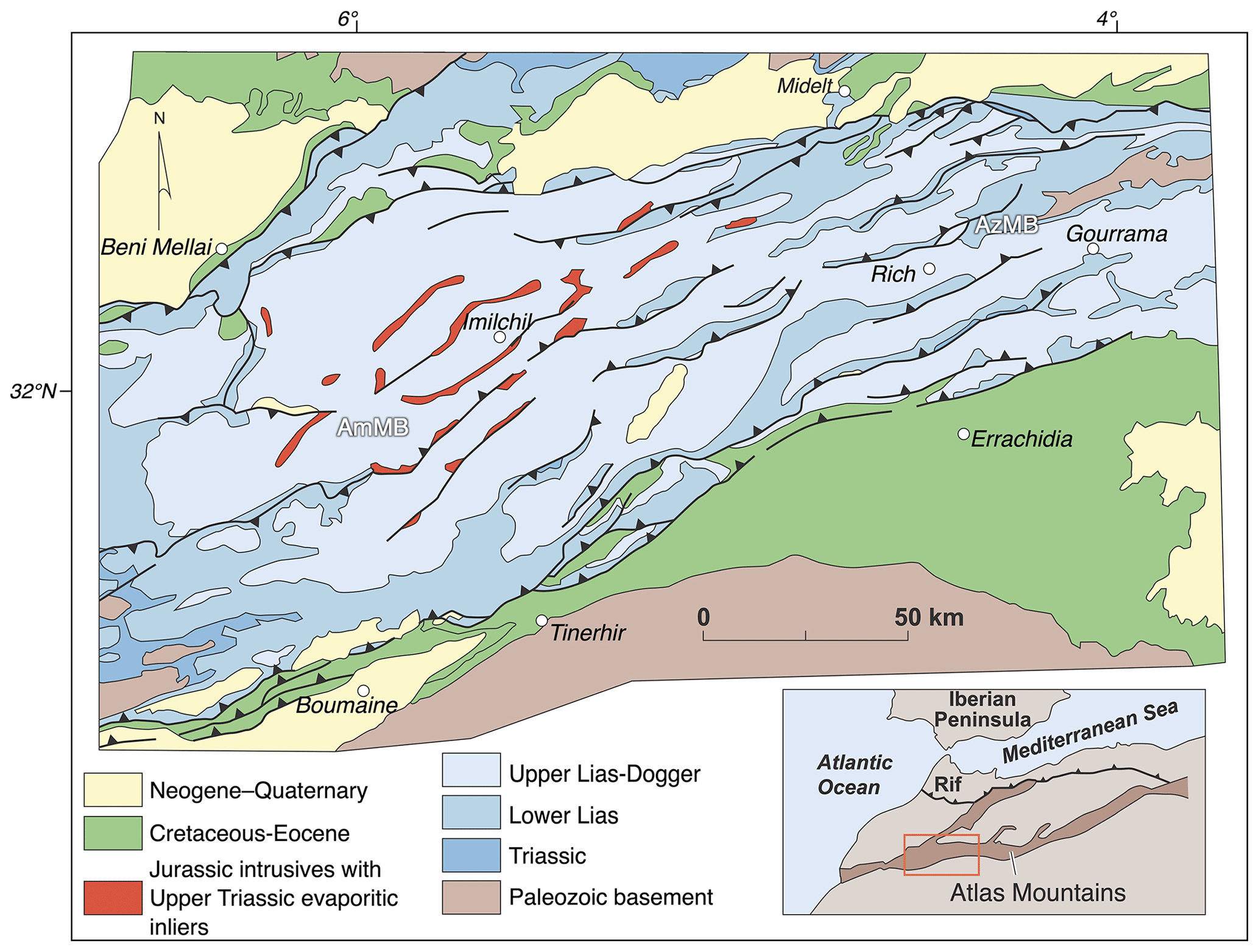
Figure 1Summary geological map of the central High Atlas of Morocco. Jurassic intrusive massifs containing Upper Triassic shale, basalt and evaporite inliers have been interpreted as former diapiric ridge that separated extensional minibasins formed during Permian to Early Jurassic punctuated rifting. AmMB: Amezraï minibasin. AzMB: Azag minibasin. Map redrawn and modified from Teixell et al., 2017.
Many experimental studies of contractional tectonics utilize silicone polymer as a detachment, sometimes with spatially variable and multiple detachment levels, usually of uniform thickness, in thrust belt studies (e.g., Couzens-Schultz et al., 2003, and see the review by Graveleau et al., 2012). Some previous physical modeling studies of basement-involved extension and inversion of salt-bearing rifts include those of Dooley et al. (2005) with application to the North Sea and Moragas et al. (2017) in their focused study on syn- and post-rift diapirism and inversion in the Moroccan High Atlas. Bonini et al. (2011) modeled detached extension and subsequent shortening of these graben, Soto et al. (2007) modeled the effects of high-level ductile detachments above a variety of listric fault geometries, and Roma et al. (2017, 2018a,b) as well as Ferrer et al. (2014, 2016) modeled extension and inversion above rigid planar and ramp-flat extensional master faults with high-level and variable-thickness salt layers. However, all the basement-involved inversion studies to date relied on non-deformable basement blocks to generate extension and subsequent inversion. Exceptions to this are the clay models of Durcanin (2009), but these models could not be sectioned and thus sections shown in this study are “hypothetical”. A new series of experiments was designed to produce segmented rift systems in deformable model materials; fill them with syn-rift evaporites; and subject them to further extension, loading, and, finally, inversion. Our goals with these models were to test the following. (1) Where and why do diapirs form in a segmented extensional rift system? (2) How much coupling is there between basement and cover separated by a relatively thick salt body during extension and contraction? (3) What styles of shortening structures form in the suprasalt section during inversion and what controls their location and style? (4) What are the styles of shortening in the subsalt section and can we get significant reactivation of extensional structures during inversion?
2.1 Model design and scaling
Our goal with these models was to generate a series of en-échelon graben across a rift system in a similar fashion to models presented in Dooley et al. (2005). They achieved this by using non-deformable wooden blocks with a series of steps, whereas we wished to generate segmented rifts using deformable materials that could be serially sectioned at the end of the model run. Previous models of segmented rift systems used offset rubber sheets to do this (e.g., McClay et al., 2002; Amilibia et al., 2005). However, these suffered from internal artifacts. As the rubber is stretched to generate extension in the overburden, it also constricts orthogonal to the extension direction, resulting in accommodation or transfer zones that are structural lows rather than highs in these locations (see Sections 2 and 5 of Fig. 8 in Amilibia et al., 2005). In order to mitigate these effects, we used a hybrid system comprising a single basal stretching sheet, a thin basal silicone detachment and a series of polymer slabs to generate a segmented rift system in the overburden (Fig. 2). The stretching rubber sheet generated extension, whilst the basal polymer layer acted as an efficient detachment (during extension and contraction). In contrast, the polymer slabs served to focus extension at these sites, in much the same way that precursor diapirs focus strain in contractional models (e.g., Dooley et al., 2009, 2015; Callot et al., 2007, 2012). Dooley and Schreurs (2012) employed a variety of polymer “crustal weak zones” to focus extension in pull-apart basins and to concentrate and perturb deformation above basement strike-slip zones. Le Calvez and Vendeville (2002), Zwaan et al. (2016), and Zwaan and Schreurs (2017) also used polymer “ridges” to focus or “seed” extensional structures in their models, and Marques et al. (2007) used wedge-shaped polymer layers to investigate transform faulting associated with ridge push. Dual motors generated the symmetric extension and contraction in our models (Fig. 2).
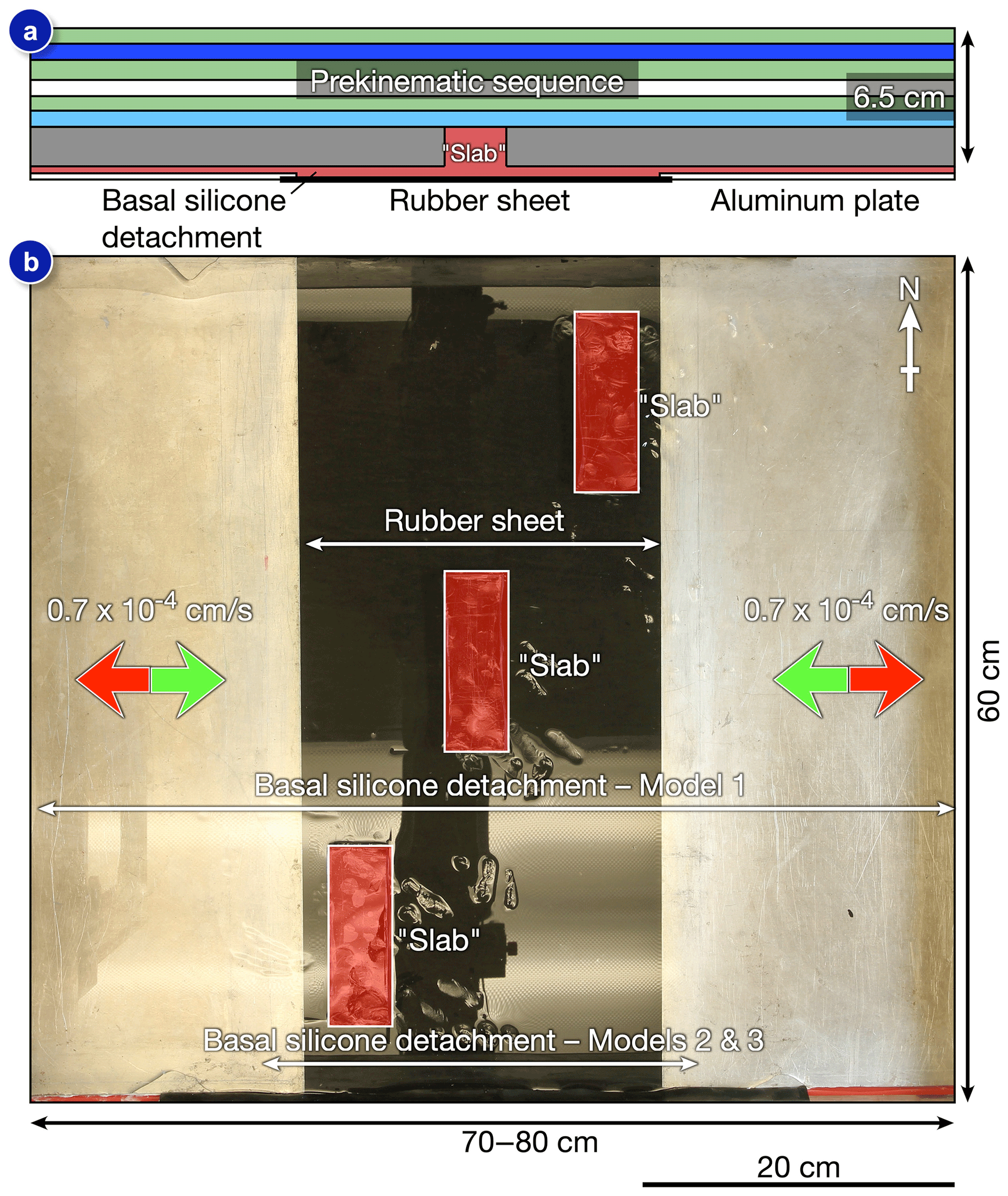
Figure 2Summary of experimental setup used in models shown in this study. (a) Cross-section view of the pre-rift setup. Models consist of a stretching rubber sheet overlain by a thin basal detachment and polymer slabs covered by a layered sand pack. (b) Overhead view of deformation rig prior to emplacement of the layered pre-rift overburden. See text for further details.
Models are dynamically scaled such that 1 cm in the model approximates to 1 km in nature (see, for example, Brun et al., 1994, and McClay, 1990, for detailed discussions on scaling). Models were conducted with combined horizontal velocities of 1.4 × 10⁻⁴ cm s−1 that yields a strain rate of 1.8 × 10⁻⁶ s−1. This rate models an extensional fault system with a moderate displacement rate (e.g., Withjack & Callaway 2000; Dooley et al., 2005). More importantly, post-salt extension was pulsed in order to allow the model salt analog to react to the imposed strain and the differential loads induced by spatially variable thickness of the synkinematic sediments added after each increment of extension. Models consist of three or four main evolutionary stages (Table 1): (1) pre-salt extension followed by addition of model salt into the main structural topography and the addition of a regional salt fringe and thin roof; (2) post-salt extension delivered in a series of pulses, as described above; (3) post-salt loading and downbuilding stage, allowing diapirs that formed in Stage 2 to continue to rise vertically; and (4) inversion, where the moving endwalls are detached from the baseplates, the baseplates are clamped in place, and motion is reversed. We focus primarily on the results of one experiment (Model 1, Table 1) in the descriptive sections and use some of the results from two other experiments (Model 2 and Model 3, Table 1) to discuss salt tectonic styles and salt migration pathways in non-inverted and weakly inverted rifts in the discussion section. The only difference between Model 1 and the other models is that the thin basal detachment layer extended across the entire model base in Model 1, whereas it was limited to just covering the rubber sheet in Model 2 and Model 3 (see Fig. 2).
Table 1Model names and values for extension and inversion for experiments described in the main text.
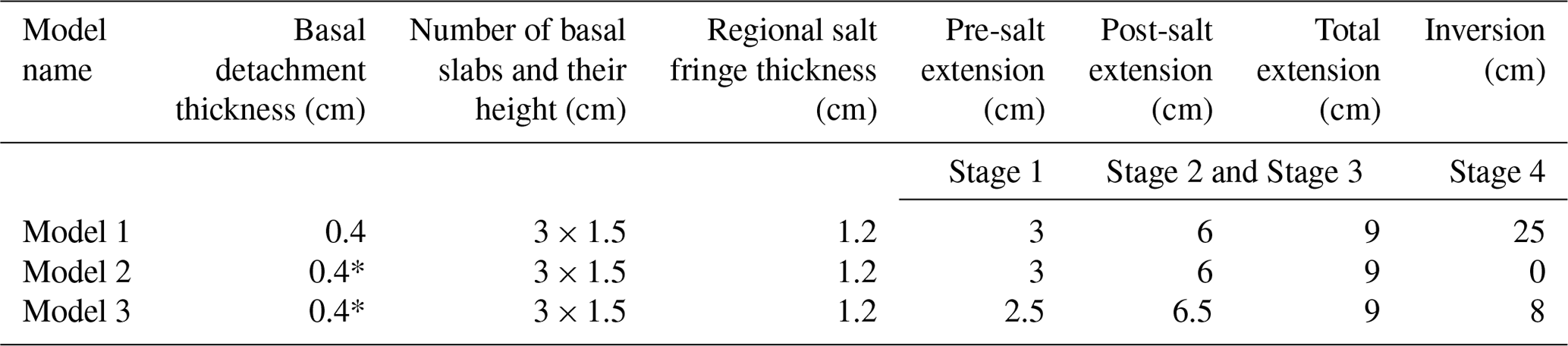
* denotes basal detachment was limited to the central region of the model.
2.2 Modeling materials
As with other physical modeling studies of salt tectonics, we simulated rock salt using ductile silicone and its siliciclastic overburden using brittle, dry, granular material. The silicone was a near-Newtonian viscous polydimethylsiloxane. This polymer has a density of 950 to 980 kg m−3 and a dynamic shear viscosity of 2.5 × 10⁴ Pa s at a strain rate of 3 × 10⁻¹ s−1 (Weijermars, 1986; Weijermars et al., 1993). In some of our models the salt analog was dyed with minute quantities of powdered pigments in order to track salt flow paths in the completed model. The layered brittle overburden comprised different colored mixtures of silica sand (bulk density of ∼ 1700 kg m−3; grain size of 300–600 µm; internal friction coefficient, μ = 0.55–0.65; McClay, 1990; Krantz, 1991; Schellart, 2000), and hollow ceramic microspheres (“glass beads”) having a bulk density of 650 kg m−3, average grain size of 90–150 µm, and typical μ = 0.45 (e.g., Rossi and Storti, 2003; Dooley et al., 2009).
The hollows spheres serve to lower bulk grain size, as well as allowing us to modify the density of the brittle overburden. Most physical models of salt tectonics have a layered brittle overburden of pure quartz sand, which creates density ratios that are much higher than those of nature. Exaggerated density ratios erroneously magnify overburden foundering, rise of active diapirs, and expulsion and extrusion of salt (Dooley et al., 2007, 2009). In our models, the pre-rift overburden sediments had a density ratio equal to that of our model salt by our varying of the sand–bead ratio in the brittle section. In this case the ratio of sands to censospsheres in the mixture was equal. This was done to minimize any density- or buoyancy-driven rise of the basal slabs that are also made of the same materials as our salt analog. In Stage 2 and Stage 3 of the model runtimes, the density of the sedimentary load was increased to 1.1–1.2 times that of our model salt, by increasing the proportion of sands in the mixture to 65%. This was done to encourage salt remobilization from beneath the extensional minibasins in Stage 2 and to keep salt structures (diapirs) growing in Stage 3. Synkinematic strata were added to the model after each 1 cm increment of extension in Stage 2, with aggradation rate governed by any rising diapirs. Similarly, during Stage 3, the height data discussed below governed the regional aggradation rate to just crest rising diapir networks.
2.3 Data capture, visualization and interrogation
Computer-controlled cameras photographed the obliquely lit upper surface of the models at set time intervals. A digital image correlation (DIC) system, consisting of a high-resolution stereo charge-coupled device (CCD) system and associated software, tracked the surface-strain history, subsidence, and uplift values, as well as displacement vectors of the top surface of the model. The speckled nature of the sand and cenosphere mixtures used in our models are ideal for this type of monitoring system (see Reber et al., 2020, for further details). Adding synkinematic layers means data are incremental for individual layers during Stage 2 and Stage 3 of Model 1. For more details on DIC monitoring techniques, see Adam et al. (2005). After completion, models were impregnated with a gelatin mixture, left to partially dry for 12 h and then sliced into closely spaced slabs. Coregistered digital photographs of these closely spaced serial sections (≤ 3.5 mm apart) yielded a 3-D voxel of the completed model. Dip sections are the sliced and photographed cross sections, whereas crosslines, arbitrary lines and depth slices are virtual sections constructed from the voxel model. As a result, the crossline, arbitrary line and depth slice images are interpolated and thus not as sharp as those derived directly from photographed dip sections. In addition, the 3-D salt volume can be extracted from this voxel by coloring the salt in each section with a known pixel value (e.g., white for a value of 255).
3.1 Stage 1: pre-salt extension
Stage 1 comprised 3 cm of uniform extension in order to generate structural topography that was infilled by our salt analog (Table 1). The basal weak slab array shown in Fig. 2 was there to ensure a segmented rift system formed. Height-change data (ΔZ; Fig. 3a) generated from our stereo-DIC system reveals the main rift system in Model 1 comprising en-échelon graben that step to the right across the underlying basal slab array (Fig. 2). Three main depotroughs are seen along the segmented rift system, separated by zones of higher intra-rift topography, i.e., accommodation zones (Fig. 3). Strain data illustrate the focused extension along the fault network across the rift system (Fig. 3b). On many faults the maximum extensional strains, and maximum width of faults, are recorded along their centers, but some deviate from this trend (Fig. 3b). Weaker extensional systems form at the margins of the model, which is far from the central rift system (Fig. 3). The accommodation zones are clearly seen in the strain data and consisted of interlocking arrays of mostly soft linked extension faults with some rotation seen at fault tips (Fig. 3b). Between the southern and central and between the central and northern subbasins, clear fault-tip rotation is seen with breaching of the major relay systems separating the subbasins (Fig. 3b).
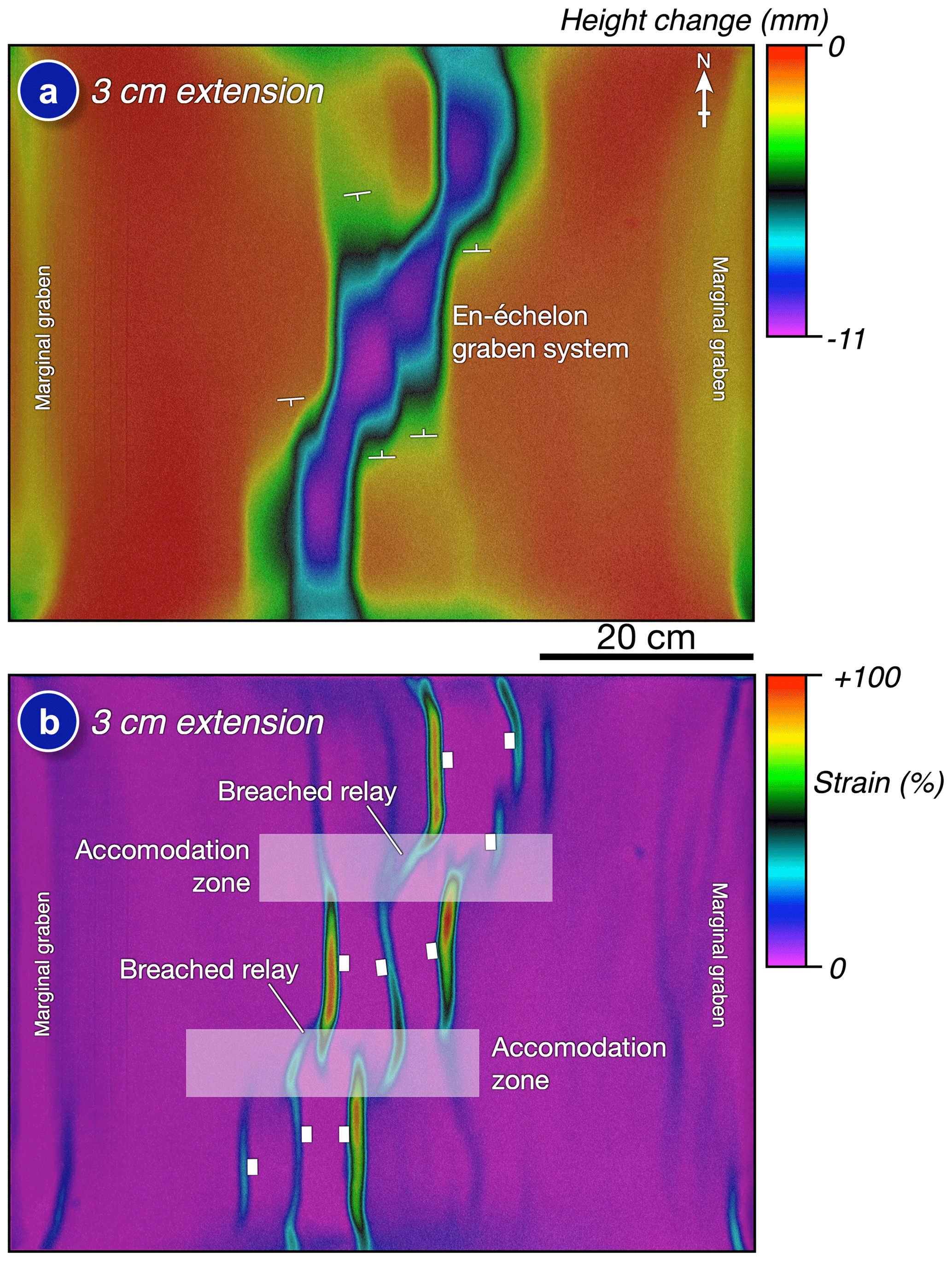
Figure 3(a) Height-change map of Model 1 after pre-salt extension. Three en-échelon graben in model center are separated by accommodation zones with relays. Marginal graben formed at the model periphery. (b) Strain map of Model 1 during pre-salt extension. Accommodation zones consist of interlocking extensional faults. Note that some relays are breached. See text for further details.
After Stage 1 extension, our salt analog was placed into the three subbasins and allowed to settle (Fig. 4a). Once this had settled and filled the structural relief, a 12 mm thick regional layer of our salt analog was emplaced across the model as a series of tiles (Fig. 4b) and allowed to degas prior to Stage 2.

Figure 4Emplacement of syn-rift salt in Model 1. (a) Pre-salt graben are infilled with our salt analog. Colored silicone was emplaced in the central graben system in order to track flow in the final cross-section views. (b) A regional salt fringe is then emplaced across the entire model.
3.2 Stage 2: post-salt extension
Our salt analog in Model 1 was buried under a thin (4 mm) sedimentary roof before undergoing a further 6 cm of extension during Stage 2 (Table 1). Figure 5 shows height-change data and strain from Model 1 after applying a total of 4 cm of post-salt extension. Synkinematic sediments were added after each 1 cm of basement extension, and the values shown in Fig. 6 are incremental for that phase of extension, i.e., 3–4 cm post-salt extension. During this period the main depotrough comprised a sigmoidal extensional minibasin located above the original offset graben system (Fig. 5a). A series of curvilinear fabrics define relatively minor surface faulting (Fig. 5a). Strains seen on the upper surface were much more diffuse and spread across the rift system than those seen in the pre-salt extension (Stage 1; Fig. 3). The strain fields formed curvilinear systems of extension that, for the most part, defined minor graben above reactive diapirs and appear to be diagnostic of detached suprasalt extension (cf. Dooley et al., 2005; Fig. 5b). Maximum extensional strains were seen adjacent to the sigmoidal depocenter, as expected, delineating the margins of the main depotrough, and in locations that were accommodation zones during the pre-salt extension phase as the cover collapsed into the developing trough (Figs. 3 and 5). Minor shortening strains are seen within the extensional minibasin or depotrough due to inner-arc contraction as it subsided into, and expelled, the salt (Fig. 5b). The marginal graben at the ends of the model continued to subside during Stage 2 (Fig. 5).
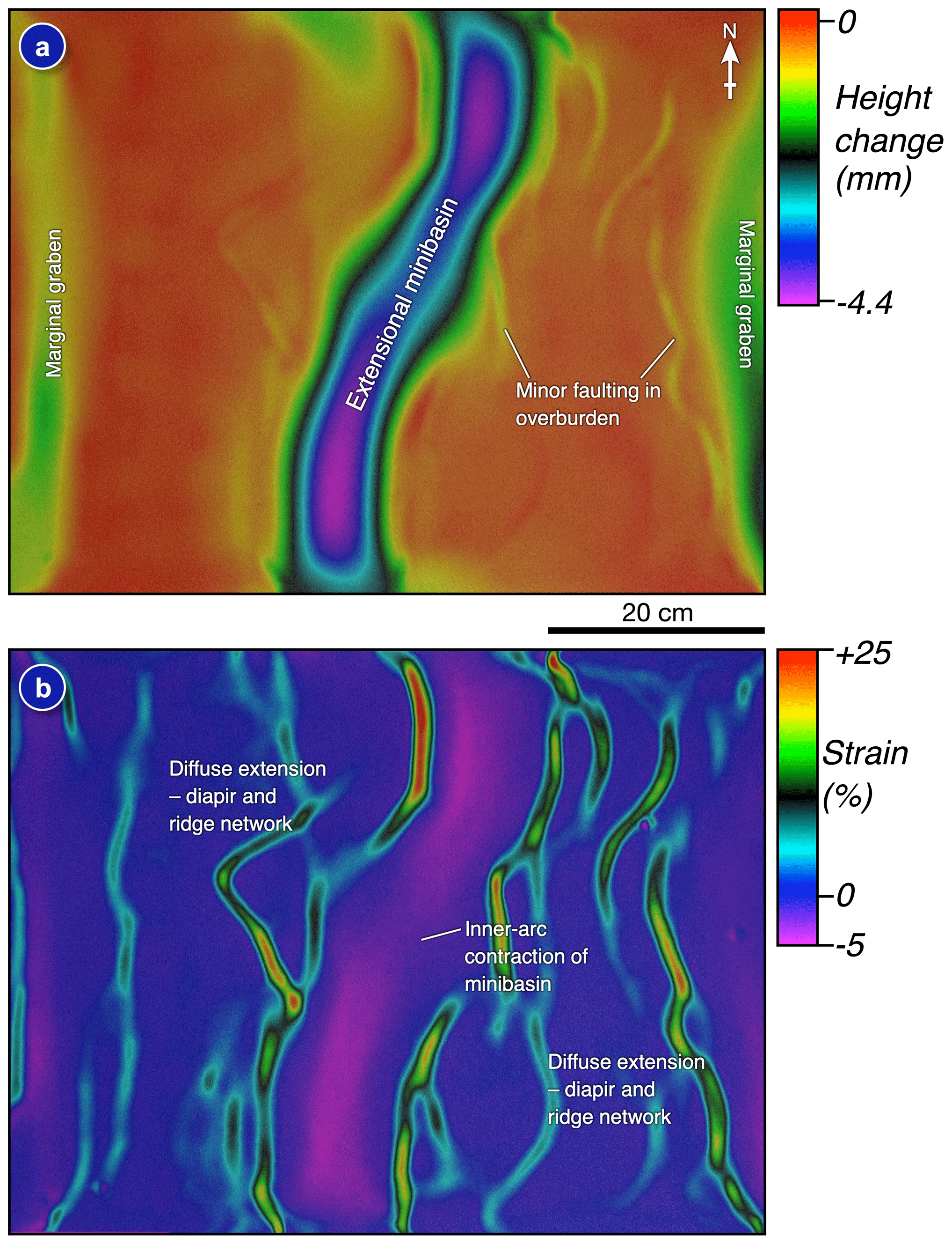
Figure 5(a) Height-change map during post-salt extension in Model 1. Post-salt extension was now 4 cm. Note the composite minibasin extending across the model center, which is above the original graben system. (b) Strain map of the same increment of post-salt extension. Note the diffuse strains in the suprasalt cover. Most extensional strains mark outer-arc extension above reactive diapirs. Note the minor shortening strains within the minibasin due to inner-arc contraction within the subsiding minibasin.
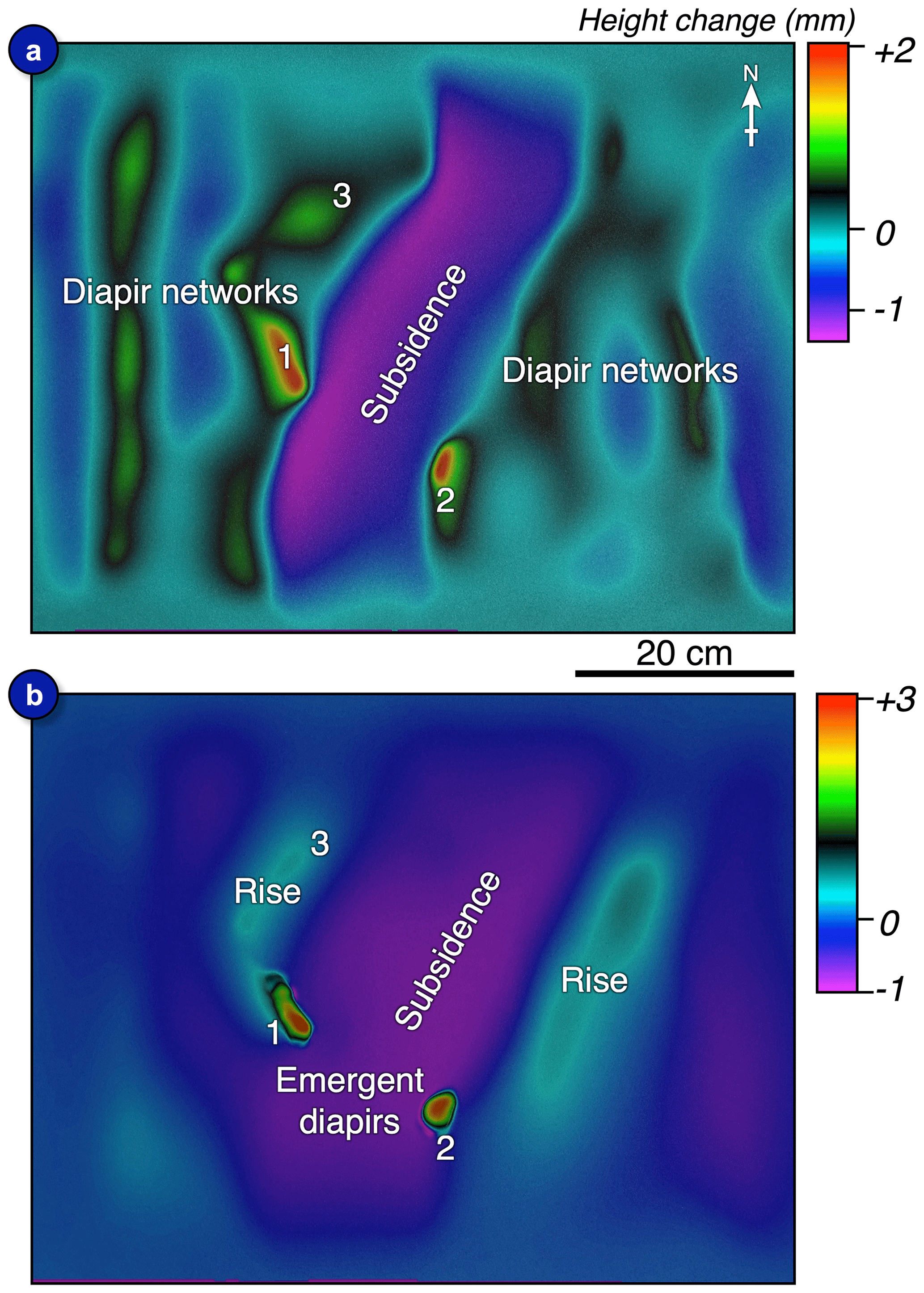
Figure 6Height-change maps of Model 1 after 16 h (a) and 48 h (b) of post-extension loading. In (a) we see the major diapir networks, formed during extension, continuing to rise as salt is expelled from beneath adjacent minibasins. After 48 h (b), loading activity is now focused on two major diapirs. See main text for more details.
3.3 Stage 3: post-extension loading
Model 1 underwent 9 cm total extension prior to moving on to a downbuilding or post-extension loading phase in Stage 3. Stage 3 lasted for 5 d and synkinematic sediments were added daily, keeping apace and gently covering any positive topography that developed whilst continuing to load negative topography.
Height-change maps of the model surface of layers 1 and 4 are shown in Fig. 6. Clearly illustrated in Fig. 6a are the rising diapir networks as salt was expelled from beneath the composite minibasin in the model center. Comparing Fig. 6a to the strain map in Fig. 5b, one can immediately see that the diapir networks closely conform to the strain patterns seen during Stage 2, evolving from reactive to passive features in Stage 3. Diapirs labeled 1–3 are all located on the footwalls of the main extensional minibasin and, more importantly, in locations that lie above, and along, what were the original accommodation zones between the original subbasins (see Figs. 3–6). More linear salt walls are seen rising adjacent to the marginal graben systems, and the extensional minibasin is flanked by upwellings along most of its length (Fig. 3). Figure 6b illustrates the height-change map after 4 d into Stage 3. Activity waned in these systems over time except for the more active and emergent diapirs (1 and 2 in Fig. 6b). Smaller amounts of salt rise are seen flanking the central region of subsidence.
3.4 Stage 4: inversion
In Stage 4 Model 1 was covered with a thin roof sequence and subjected to 25 cm of lateral shortening (Table 1). Height-change maps reveal the evolution of the model during inversion (Fig. 7). As expected from previous studies (e.g., Dooley et al., 2009, 2015; Callot et al., 2007, 2012; Duffy et al., 2018), initial shortening resulted in rejuvenation of the two main diapirs formed during Stage 2 and Stage 3 (1 and 2 in Fig. 7a). This was followed by uplift of the composite minibasin system and the formation of a series of linear and curvilinear uplifts (Fig. 7b). These uplift patterns are very similar to the ridge networks seen during Stage 3 (compare Fig. 6a with Fig. 7b). With continued shortening the minibasin system continued to rise and salt emerged from diapir 2 (Fig. 7c). The network of curvilinear flanking uplifts continued to rise and become more prominent, and intervening lows shrank in area as they were overthrust (Fig. 7c). At the end of the experiment, Model 1 consisted of a central plateau cored by the inverted minibasin system and flanked by linear and curvilinear thrust ridges with narrow intervening lows (Fig. 7d). Salt sheets emerged from diapirs 1 and 2 and flowed down into the flanking topographic lows (Fig. 7d).
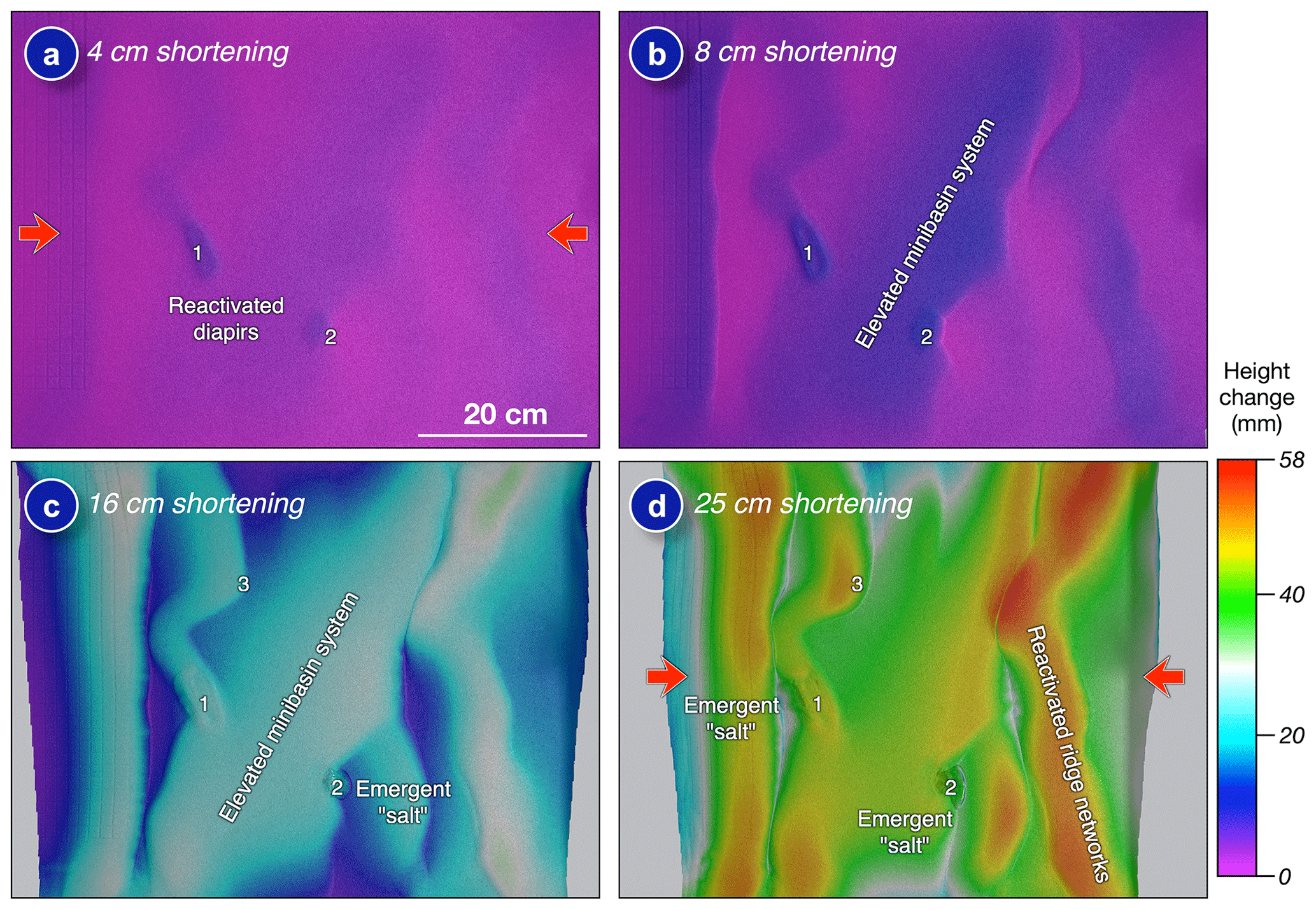
Figure 7Height-change maps (a–d) reveal the evolution of Model 1 during inversion. The initial shortening and uplift process was focused on the diapirs formed during extension and loading (a), followed by uplift of the composite minibasin above the model center and rejuvenation of the diapir and ridge networks (b–d).
The final overhead view of Model 1 is shown in Fig. 8. In this we see the central uplifted minibasin system forming an oblique plateau across the model and flanked by the linear and curvilinear faulted ridge network. Flow directions of the salt sheets emanating from diapirs 1 and 2 are indicated by red arrows (Fig. 8). Major fault scarps were partially degraded and exposed older strata, and some scarps abut or override scarps with an opposite sense of dip (Fig. 8). On the right side of the model two fault scarps abut in the south and then coalesce forming a very narrow fault zone (Fig. 8). These geometries and relationships are revealed by a series of four sections through Model 1 (Fig. 9). The four sections illustrate the decoupled nature of deformation between sub- and suprasalt strata (Fig. 9). The main feature is the structurally elevated extensional minibasin system that trended obliquely across the model (Figs. 8 and 9). For much of the strike length, this is a flat-topped feature and bounded on either side by detached suprasalt thrusts or secondary thrust welds as Diapirs 1 and 2 were squeezed shut (Fig. 8 and Section 33 and Section 55 in Fig. 9). Structural elevation of this minibasin system was partly aided by the inversion of subsalt graben that form inversion anticlines in the subsalt strata (Fig. 9; see the next section for further discussion). Primary welds denote where the minibasins have touched down on the inverted subsalt strata. Also of interest in the suprasalt strata are emergent sheets and isolated salt bodies sourced from the squeezed and welded diapirs (e.g., Section 33 and Section 55 in Fig. 9), salt-cored thrusts and related secondary welding of portions of these as salt was ejected, and the hanging wall touched down onto the footwall (e.g., Section 33, Section 86 and Section 106, Fig. 9). Other structures in the suprasalt section include highly overthrust pop-down structures and narrow upright fault zones as hanging walls collided during shortening (Section 86, Fig. 9). A curious structure is observed in many sections and termed an “S” structure due to its shape (see Section 55 and Section 86 in Fig. 9). We will discuss the origins of this structure in the Discussion section. In the subsalt strata, structures are very different, consisting of inverted and heavily deformed graben systems in both the center and margins of the model as well as new pop-up structures (Fig. 9).

Figure 8Overhead view of Model 1 after 25 cm shortening. Diapirs 1 and 2 are clearly visible in this view as emergent salt sheets. Section lines are those shown in Fig. 9. See text for further details.
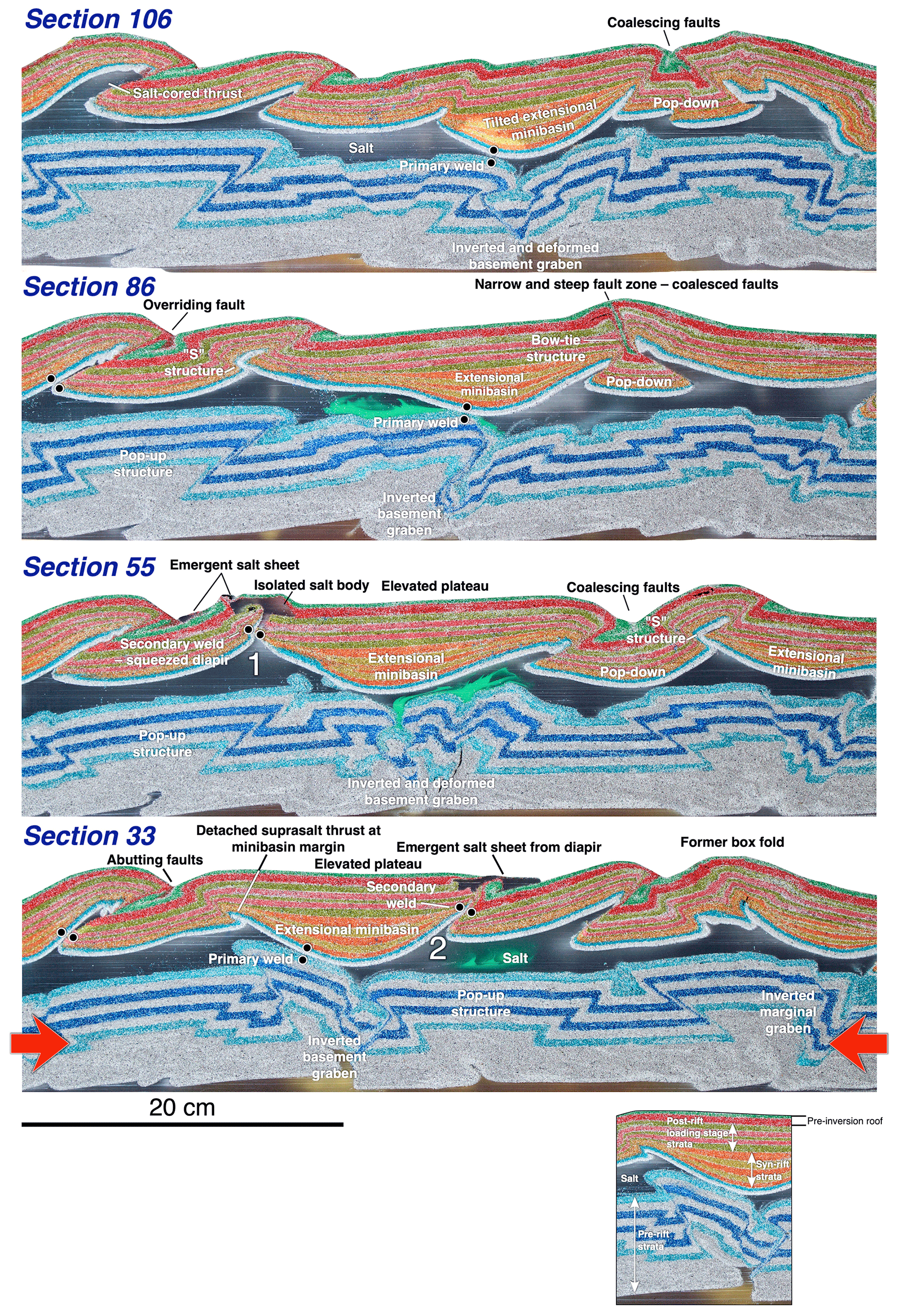
Figure 9Representative sections through Model 1. Locations are shown in Fig. 8. Inset shows the model stratigraphy.
In this section we focus on (1) the formation and location of diapirs during extension and post-extension loading, (2) shortening styles and location in the suprasalt section during inversion, (3) shortening styles and locations in the subsalt section, and (4) comparison of model results to examples from the High Atlas in Morocco.
4.1 Diapir formation and location during extension
In Model 1 the main diapirs (diapirs 1 and 2, Fig. 6) and associated salt wall or ridge networks formed in the footwall of the main extensional systems that flanked the composite extensional minibasin. More specifically, the most active diapirs formed in locations spatially associated with the interlocking accommodation zones that originally separated the subbasins (Figs. 3, 5 and 6). These locations are similar to those documented in Dooley et al. (2005), but the transfer zones in those models were vertical and rigid. Model 2 was run with almost identical parameters as Model 1, but it was not inverted, preserving the diapir geometries and locations (Table 1 and Fig. 10). Figure 10a shows the height-change map that evolved during Stage 1 of this model (see Table 1), consisting of an en-échelon series of three graben that run obliquely across the model, similar to that seen in Model 1 (see Fig. 3a). The only difference that Model 2 showed was the presence of marginal graben that formed closer to the main rift system than that seen in Model 1. This was attributed to the narrower basal silicone detachment used in Model 2 (Fig. 2 and Table 1). Likewise, the continued evolution of Model 2 through Stage 2 and Stage 3 was very similar to that seen in Model 1 (compare Fig. 10b and c with Figs. 5a and 6a). The diapir network geometries and most active diapirs in Model 2 were also very similar to those seen in Model 1.
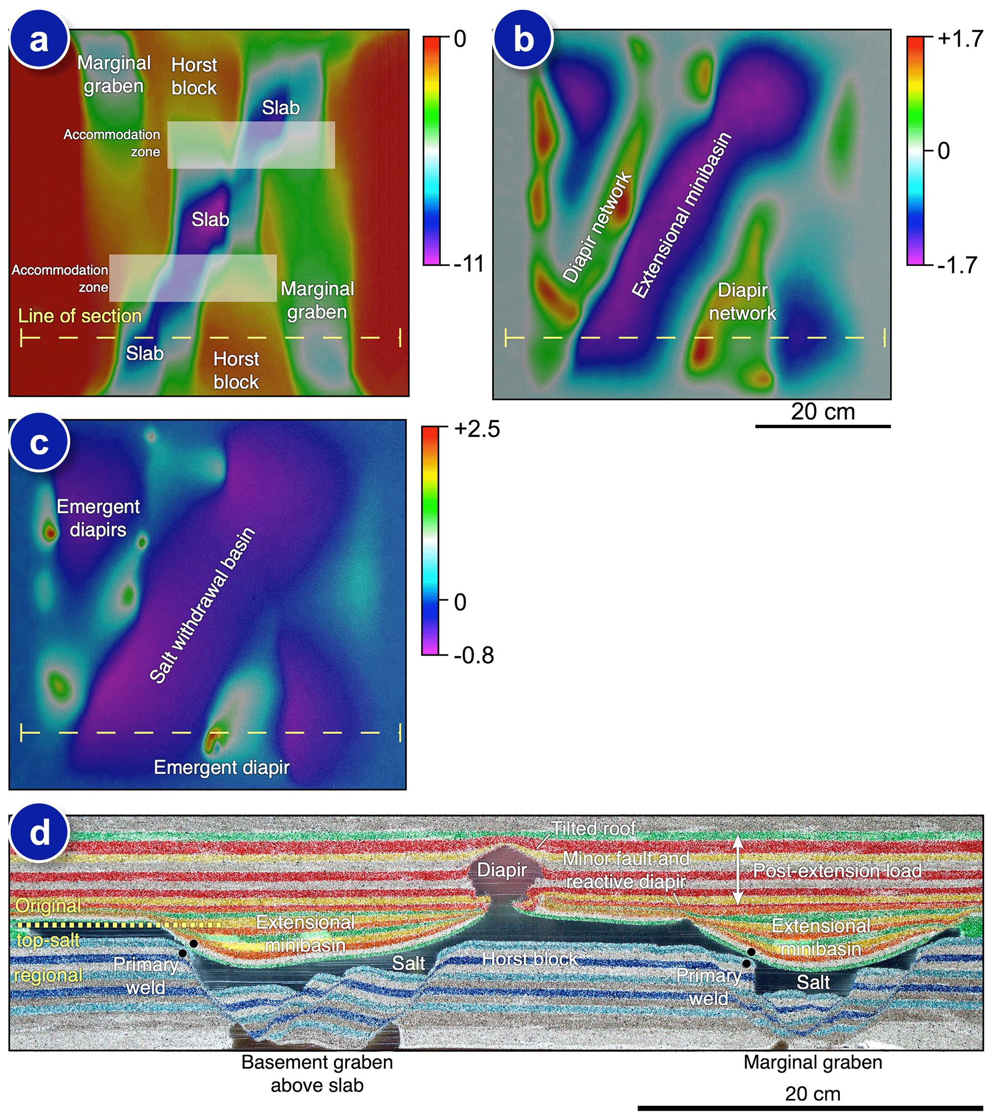
Figure 10Details from Model 2 (see Table 1). (a) Height-change map that evolved during Stage 1 of Model 2. (b) Height-change map of Model 2 during post-salt extension. (c) Height-change map of Model 2 during post-extension loading. (d) Cross section from Model 2 illustrating extensional minibasins and diapirs of varying heights formed in the footwalls of the subsalt graben. See text for further details.
A section from Model 2 illustrates that the extensional minibasins formed above the main graben and diapirs located in the footwalls of these graben (Fig. 10d). As we saw in the strain maps for Model 1, there was only minor discrete extension in the suprasalt strata and these are cored by reactive diapirs (Fig. 10d). The main diapir in this section is located in the footwall of the main graben system, and just along strike from the accommodation zone that separated the southern and central subbasins (Fig. 10a and d). Salt expelled from beneath the subsiding minibasin flowed up onto the footwall and helped feed this growing salt diapir. We believe that salt was also preferentially expelled up and along the accommodation zones that separated the original subbasins and into these growing diapirs, as these accommodation zones have more gentle relief compared to the steep faults that bounded the minibasins, thus offering a more efficient conduit for salt flow.
In order to corroborate this concept of preferred flow up and along transfer or accommodation zones, images from a third model, Model 3, are shown in Fig. 11. Model 3 was subjected to the same amount of extension as Model 1, but with a very limited amount of inversion (Table 1). In addition, the lack of a basal detachment across the entirety of the model base meant that shortening in the subsalt section was limited to shortcut thrusts close to the margins of the deformation rig that transferred shortening up to the weaker suprasalt section, with minimal shortening seen in subsalt strata in the central portion of the rift system (Fig. 11a–e; Table 1). The lack of deformation in the subsalt strata means that primary welds seen in the sections in Fig. 11c–e occurred during extension rather than during shortening. Depth slices from Model 3 illustrate the composite, stepped, minibasin that formed above the en-échelon rift system (Fig. 11a and b). The yellow marker salt that initially occupied the central graben of the rift (Fig. 11f) is seen to be expelled up and out of this graben system into the footwall, where it helped inflate reactive diapirs that initially formed along these locations (Fig. 11a-c; see reactive diapir on the right side of Fig. 10d for a non-inverted example). Model 3 also had substantial diapirs that flanked the rift in similar positions to those of Model 1 and Model 2, and yellow marker salt is seen to flow along and up the, now faulted, lower-relief accommodation or transfer zones and into these diapirs (Fig. 11d and e). Thus, salt flow during extension and post-extensional loading in Model 3 was multidirectional, being driven by differential loading out and up onto the intra-rift horst blocks both up the main subsalt faults and along lower-relief pathways such as the transfer zones that separated the subbasins in this rift system. Flow up and along these conduits was eventually curtailed or stopped by primary welding (Fig. 11c–e).
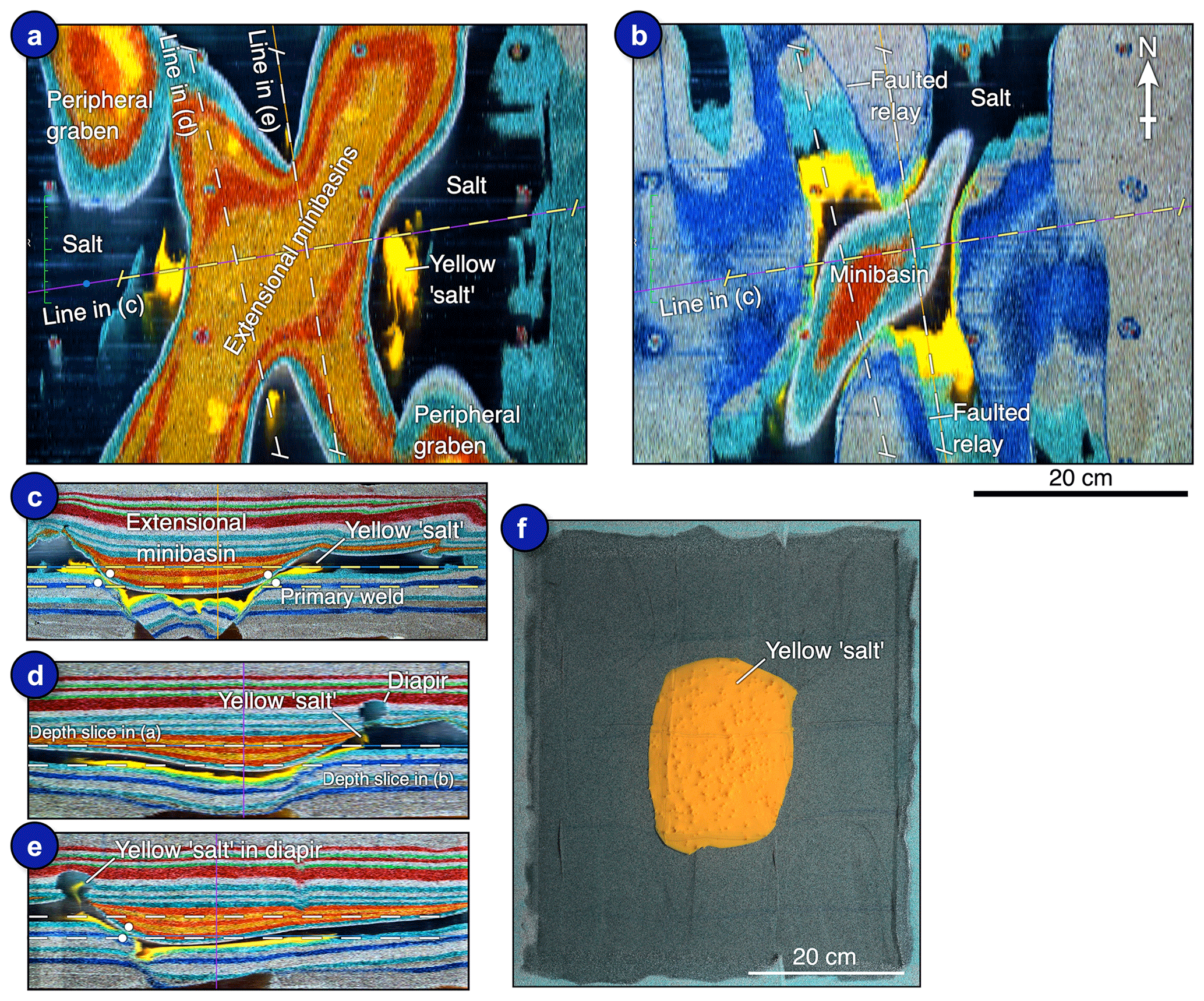
Figure 11Details of Model 3. (a and b) Depth slices through Model 3. (c–e) Arbitrary lines through a portion of Model 3. (f) Original location of yellow marker “salt” in the central graben of Model 3. See text for further details.
4.2 Shortening in the suprasalt section
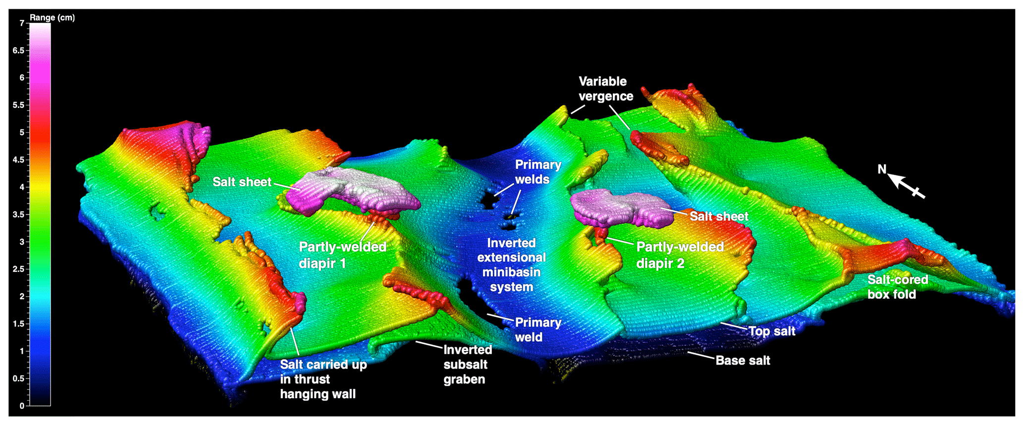
Figure 12 shows the salt volume that was extracted from the serial sections and exported as a point cloud. This image beautifully illustrates the structural style in the shallow section. The central part of the model is dominated by the inverted extensional minibasin system that forms an oblique structural low in the top salt surface. Primary thrust welds are denoted by gaps in the data, as the subsalt graben were inverted, welded against the base of the suprasalt strata and structurally elevated the minibasin system (Fig. 12). Note that the position of the primary welds in Model 1 (Figs. 9 and 12) differs to those seen in our non-shortened or mildly shortened Model 2 and Model 3 (Figs. 10 and 11). In Model 2 and Model 3 the primary welds are located at the minibasin margins where the it welded down onto, or adjacent to, the crest of the footwall block (Figs. 10 and 11). In Model 1 primary welds are located more toward the center of the minibasin and are related to the inversion of the subsalt graben system. Any welds that formed at the minibasin margins during Stage 2 extension and Stage 3 downbuilding in Model 1 were sheared off during inversion in a similar fashion to that documented by Roma et al. (2018b). The minibasin system is typically flanked by outward-vergent salt-cored thrusts, secondary thrust welds, and remnant high-level salt bodies or sheets (diapirs 1 and 2, Fig. 12). Thrust vergence reverses toward the margins of the model, and structures vary from salt-cored thrusts to box-like thrusted folds (Fig. 12).
Shortening in the suprasalt section is primarily controlled by the diapir and ridge network that formed during extension and post-extensional loading. This is clearly illustrated in Fig. 13, which shows a height-change map, depth slice and dip section from Model 1. The diapir-ridge networks, labeled a–e in Fig. 13, localized shortening structures because these are where the overburden was thinnest and thus weakest, and the diapir networks helped to focus deformation. Deformation in the shallow section is clearly detached from the subsalt structures, except where the minibasin system welded onto inverted subsalt graben (Figs. 9, 12 and 13c). Height-change maps from the inversion phase also illustrate this reactivation of the pre-inversion diapir-ridge network (compare Figs. 7 and 13). Minibasin subsidence patterns in Model 1 were primarily symmetric during extension and post-extensional loading, as evidenced by height-change maps (Figs. 5 and 6), and by the stratal geometries seen in cross sections (Fig. 9). During inversion the main minibasin system was structurally uplifted by the inverting subsalt graben (Fig. 7), with little or no internal deformation except at the minibasin margins where suprasalt thrusts developed (Figs. 9 and 13c). Only minor tilting caused by shortening of the main minibasin system is seen in the northern part of the model (Section 106, Fig. 9). Smaller minibasins that developed above the marginal graben systems exhibit more severe tilting as they were carried up in the hanging walls of major suprasalt thrusts (Section 33 and Section 55, Fig. 9).
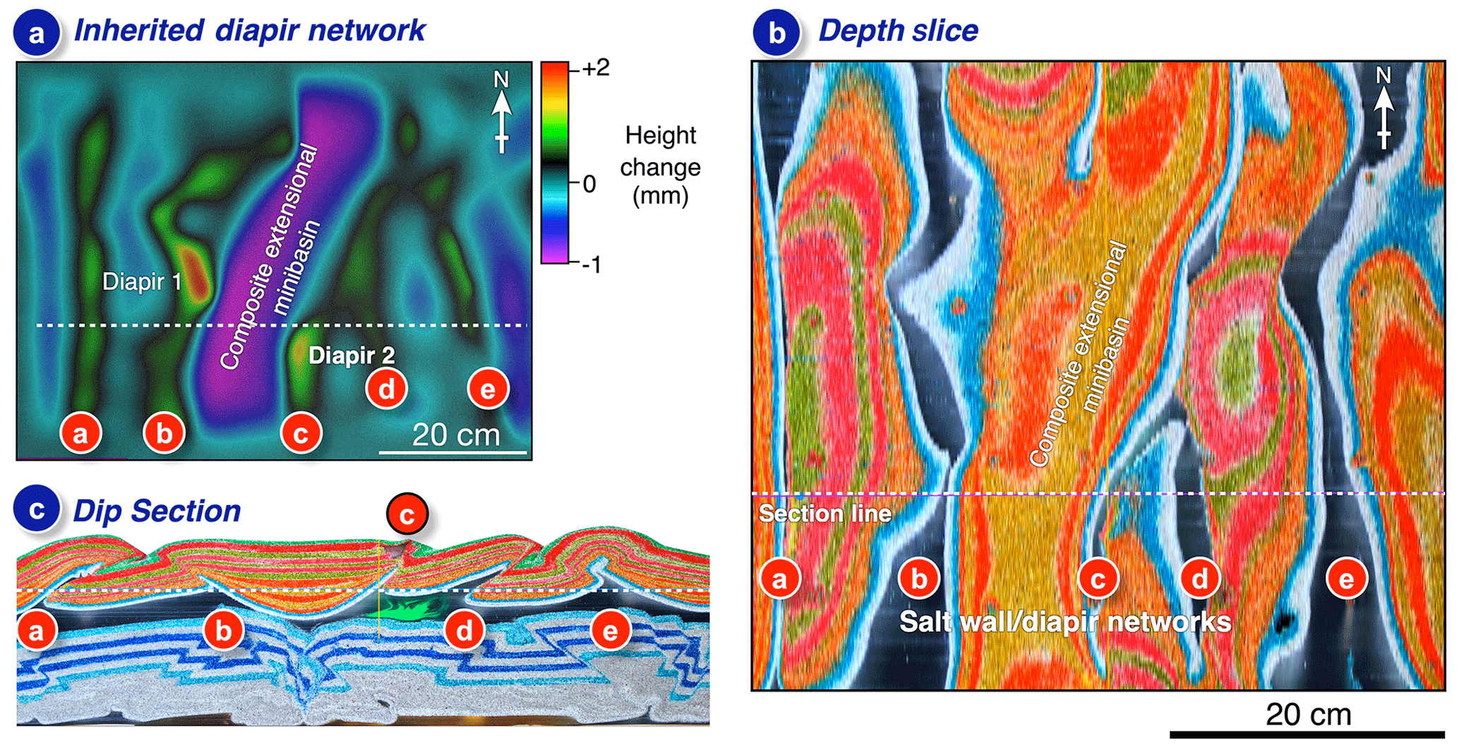
Figure 13(a) Height-change map from Stage 3 of Model 1 illustrating the diapir and ridge networks that formed during extension rising during post-extension loading. (b and c) Depth slice and dip section through Model 1 illustrating the five (a–e) main diapir networks.
As mentioned in Sect. 3.4, there is a curious structure observed in suprasalt strata in some sections through Model 1 that is termed an S structure due to its shape (Section 55 and Section 86, Fig. 9). This structure is found in a deformed salt-cored box fold in the southern part of the model (Figs. 9 and 12). A series of sections through this structure give a pseudo-temporal evolution of this structure (Fig. 14). The structure started as a faulted box fold, localized along a salt wall (e in Fig. 13), that initially formed during extension and post-extension loading. One of the hinges began to fail on one side of this box fold and eventually limb failure occurred, forming a small weld as the core began to narrow (Fig. 14a-b). Eventually salt in the core was expelled and the limbs welded, leading to the S geometry (Fig. 14c).

Figure 14Detailed views (a–c) of sections through Model 1 illustrating the evolution of an S structure.
4.3 Shortening in the subsalt section
We noted briefly in Sect. 3.4 that deformation in the subsalt strata is very distinct from that seen in suprasalt strata (Fig. 9). In subsalt strata the most obvious structures are the pop-up structures in cross-section views, and none of these are linked to structures in the shallow section (Fig. 9). However, the most interesting structures are found along the central portions of the model where the pre-salt graben have been strongly deformed and inverted (Fig. 9). Some of these structures form the highest subsalt relief seen in Model 1 (e.g., Section 33, Fig. 9). Height-change maps from Stage 4 of Model 1 clearly illustrate that the main minibasin system was preferentially uplifted as an intact block during shortening (Fig. 7). This uplift was thus a result of preferential inversion of the subsalt graben system. This is borne out in cross-section views through Model 1 that clearly show uplift of the main minibasin system as a coherent block forming an almost flat plateau along the length of the center of Model 1 (Figs. 7–9). Figure 15 shows detailed views of a non-inverted graben from Model 2 and an inverted graben from Model 1. In Model 2 the non-inverted section of the structure consists of a mildly asymmetric graben with a smaller keystone graben formed against the more dominant right-side boundary fault (Fig. 15a). Figure 15b shows a portion of Section 33 from Model 1 (Fig. 9). In it we see a highly inverted basement graben system with a keystone graben system on the right margin as in Model 1 (Fig. 15a–b). Inversion of this graben was asymmetric with greater uplift of the left side forming an inversion anticline that structurally elevated the suprasalt minibasin (Fig. 15b). Based on the geometry of the non-inverted model, the right side of the graben also saw significant inversion before being overthrust by a new subsalt thrust (Fig. 15b). More minor new thrusts are seen to the left of the graben system. Only a minor amount of structurally induced tilting is seen in the suprasalt sequence (2.5∘, Fig. 15b), attributed to the primary weld being slightly off the midpoint of the minibasin. Detached outward-vergent thrusts are located at the minibasin margins (Fig. 15b).
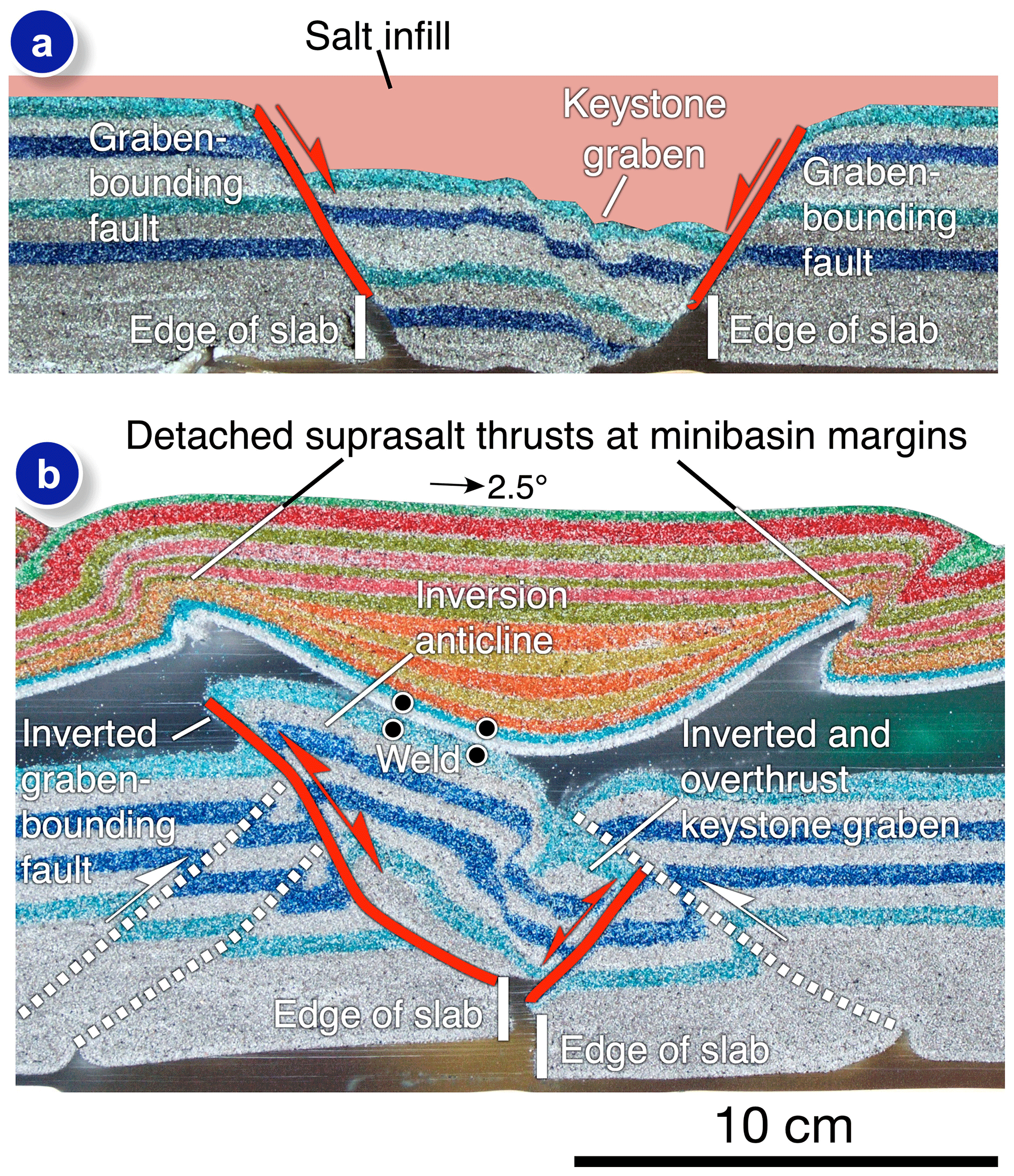
Figure 15(a) Detailed view of a non-inverted subsalt graben from Model 2. Note the asymmetric geometry and the formation of a keystone structure. (b) Detailed view of an inverted subsalt graben from Model 1. Inversion of this graben uplifted and welded the overlying extensional minibasin.
As noted by Amilibia et al. (2005), amongst others, inversion of normal faults in laboratory models using sand is quite limited, sometimes being seen at shallow fault tips, but bypass or shortcut faults are far more common. Fault reactivation in nature can occur under stress levels lower than that required to initiate new faults (e.g., Sibson, 1995), due to pre-existing faults having a lower cohesive strength and friction coefficient than that of intact rock (Anderson, 1951). The lack of significant reactivation in sandbox models can be explained by the relative lack of difference between the strengths of faulted and unfaulted sands, favoring the formation of new shortcut faults in more favorable orientations (see Amilibia et al., 2005, and Bonini et al., 2011, for more details). Significant reactivation of graben-bounding faults in our models (see Section 33 and Section 106 in Fig. 9; Fig. 15b) is attributed to two factors. The first is the presence of the weak basal slabs that initially focused extension. Figure 15a shows remnant horns of the polymer on either side of the graben, and during shortening these would help to focus initial shortening onto the graben system in the central part of the model, much like the way that precursor diapirs focus shortening in purely contractional experiments (e.g., Callot et al., 2007; Dooley et al., 2009, 2015; Duffy et al., 2018). The second, and likely more important, reason is interstitial infiltration of polymer into a narrow zone of the brittle section forming a hybrid rheology along the pre-existing faults. This results in a slight change in color of the granular materials at the sand–silicone interface, which is just visible in Fig. 15. Prior to inversion the base and sides of the graben were in contact with silicone, resulting in interstitial infiltration (Fig. 15a). The upper portions of the graben-bounding faults were also in contact with silicone, again allowing for interstitial infiltration (Fig. 15a). During shortening this interstitial infiltration acted as a “lubricant”, allowing reactivation and inversion of these faults (Fig. 15b). This phenomenon of interstitial infiltration has been observed in other laboratories that model salt tectonics with the same materials (O. Ferrer, personal communication, 2020) and is likely strongly dependent on the grain size of the strata adjacent to the salt analog. Faults in the granular materials used in physical models are generally dilatant, which would enhance this infiltration phenomenon.
4.4 Comparison to examples from the Moroccan High Atlas
Saura et al. (2014) documented that inversion-related deformation in the central High Atlas of Morocco is mainly focused on minibasin margins with little internal deformation of these minibasins, with diapirs that originally separated these extensional minibasins soaking up much of the deformation, as is seen in our Model 1 (Fig. 9). One such example is the Amezraï minibasin (Fig. 16a; Saura et al., 2014; Moragas et al., 2017; see location in Fig. 1). As in our Model 1, the Amezraï minibasin formed above a basement graben system and was flanked by complex diapirs located in the footwall of this graben system (Fig. 16a-b). After inversion these flanks are the sites of significant upturn of flanking strata, thrusts welds and remnant pedestals, similar to structures found in Model 1 (Fig. 16a and b). Similar geometries have just been described from the Maestrat Basin in Spain (Verges et al., 2020, see their Fig. 13). The Azag minibasin lies further to the ENE along the central High Atlas (Figs. 1 and 16c; Teixell et al., 2017). Again, this minibasin formed above a basement graben or half-graben system before being caught up in Alpine shortening, resulting in the welding of adjacent diapirs (thrust or secondary welds; Fig. 16c; Teixell et al., 2017), as seen in Model 1. The Azag minibasin also displays significant tilting in the E–W cross section of Fig. 16c. Minibasins can tilt during subsidence either before or after welding (Rowan and Weimer, 1998; see Jackson et al., 2019a, for more details), but the stratigraphic architecture of the Azag minibasin consists primarily of bowl- and tabular-shaped units indicating relatively symmetric subsidence during minibasin growth. Significant tilting of minibasins caused by shortening is seen in some locations in our Model 1 (Fig. 16d); thus, by analogy, the tilting and welding seen in the Azag minibasin is attributed to Alpine shortening and basement uplift.
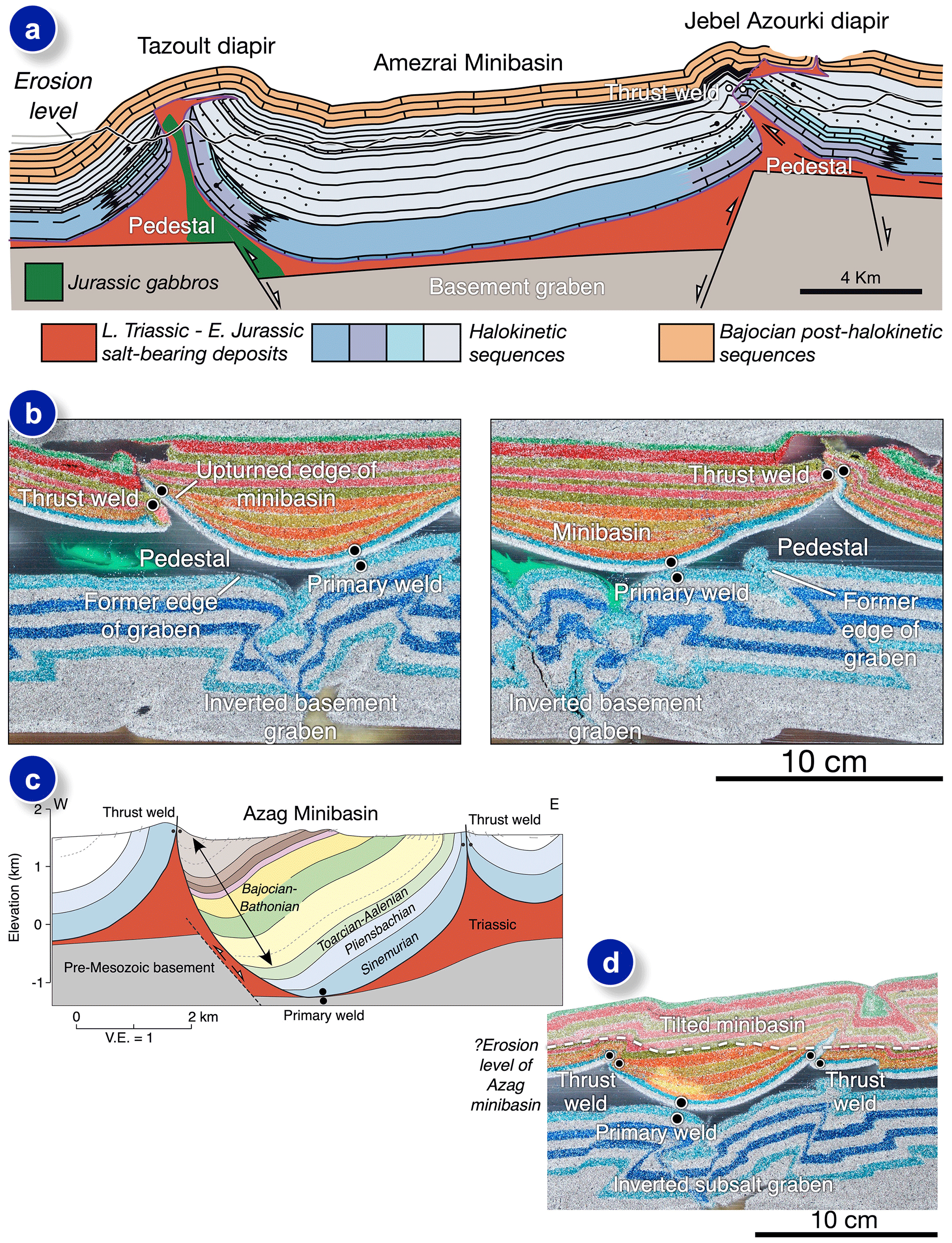
Figure 16(a) Cross section through the Amezraï minibasin, Moroccan High Atlas. Note the uptilted minibasin margins, lack of internal deformation within the minibasin, and the complex flanking diapirs and thrust welds. Redrawn from Moragas et al. (2017). (b) Detailed views of minibasin margins and associated secondary thrust welds from Model 1. (c) E–W cross section through the Azag minibasin. Note the thrust welds and tilted nature of the minibasin. Redrawn from Teixell et al. (2017). (d) Detail of a section from Model 1 illustrating a tilted minibasin, primary weld on top of an inverted subsalt graben and secondary thrust welds on either side of the minibasin.
One notable difference between our model results (Figs. 9 and 16b) and the example sections shown in Fig. 16a and c is the amount of deformation seen in the basement or subsalt strata (Figs. 9 and 16b). Basement geometries shown in Saura et al. (2014) and Teixell et al. (2017) are inferred due to lack of exposure. The geometry of the basement graben system beneath the Amezraï minibasin shown in Saura et al. (2014) was actually modified by Moragas et al. (2017) based on the results of their physical modeling study. In these natural examples the basement is shown as flat-topped as sub-salt shortening was taken up by simple fault reactivation and vertical uplift of hanging-wall blocks (Fig. 16a, c). If our physical models are indicative of the deformation intensity one would expect to see in the subsalt basement, then these more pervasive damage zones could have significant implications for fluid flow and for structural topography at the base of salt. However, our model basement consisted of essentially cohesionless materials, and it likely does not accurately represent the strength of basement rocks in the High Atlas or crystalline basement in general. An alternative explanation is that the amount of shortening in Model 1 was simply far more than that experienced in the central High Atlas. More work is required on this topic. Another topic that requires more study is the geometry of the salt isopach across a basin. In our Model 1 the decoupling between basement and suprasalt strata during both extension and inversion was enhanced by the presence of a salt fringe that covered our entire rift basin. In nature this is unlikely to be the case and many natural examples of syn-rift salt-bearing basins illustrate the absence of salt across intra-basin horst blocks (e.g., the Scotian margin; Kendell, 2012) or where the salt has variable depositional thickness and influences the degree of coupling between basement and suprasalt strata (e.g., Coleman et al., 2017). The degree of coupling between basement and suprasalt cover is not only dependent on thickness variations of the evaporite sequence but also the composition, or mobility, of the evaporites (e.g., Jackson et al., 2019b).
Our physical models successfully generated segmented rift systems in a deformable basement that were subsequently infilled with a salt analog and subjected to further extension and finally inversion. During extension and subsequent downbuilding, diapir and ridge networks formed that exerted a strong control on deformation styles and patterns during subsequent inversion. Diapir networks formed primarily in the footwalls of the basement fault system, similar to that described by Dooley et al. (2005) and Moragas et al. (2017). Diapiric growth was encouraged by salt expulsion from beneath the subsiding extensional minibasin systems that formed above the original basement graben, with major diapirs forming consistently in the locations of major relay systems or interlocking transfer zones that originally separated the en-échelon basement graben. These more gently dipping structures facilitated more efficient salt expulsion driving diapiric growth at these locations. Extensional deformation in suprasalt strata was strongly decoupled.
Inversion of these salt-bearing rifts produced strongly decoupled shortening belts in basement and suprasalt sequences. In the suprasalt section deformation geometries and locations were primarily controlled by the salt diapir network produced during extension and subsequent downbuilding with thrusts that formed minibasin margins where the overburden was thinnest and weakest. Extensional minibasins display little or no internal deformation as deformation was soaked up by diapirs and by these marginal thrusts in a similar fashion to observations from the central High Atlas of Morocco and other inverted basins. Complex structures form where salt-cored box folds weld shut by hinge and limb failure. In the subsalt section the structural style is very different, consisting of strongly inverted and pervasively deformed graben systems along with the formation of new pop-up structures. Inversion of these graben uplifted and welded the composite extensional minibasin system forming an almost flat-topped plateau across the center of the model. Significant reactivation of graben-bounding faults during inversion was aided by interstitial infiltration of our salt analog that helped lubricate the precursor faults.
Additional data from the experiments presented in this study are available on reasonable request from the lead author.
TD designed and ran the experiments with input from MH. TD processed photographic and strain data from the experiments. TD prepared the article and figures with contributions from MH.
The authors declare that they have no conflict of interest.
This article is part of the special issue “Inversion tectonics – 30 years later”. It is not associated with a conference.
Tim P. Dooley thanks James Donnelly, Nathan Ivivic, Brandon Williamson and Rudy Lucero for logistical support in the modeling laboratories. Nancy Cottington is thanked for drafting Fig. 1 and portions of Fig. 16 and for colorizing the salt analog in each dip section from Model 1, allowing Tim P. Dooley to generate the 3-D salt volume shown in Fig. 12. The authors thank Jaume Vergés (CSIC, Barcelona) and Grégoire Messager (Equinor, Norway) for initially introducing them to the salt tectonics of the Moroccan High Atlas. Antonio Teixell and Oriol Ferrer are thanked for their kind and thorough reviews of an earlier version of this article. Piotr Krzywiec is thanked for editorial handling and for initially encouraging the lead author to submit a manuscript to this special issue. Publication was authorized by the director of the Bureau of Economic Geology, Jackson School of Geosciences, The University of Texas at Austin.
This study was funded by the Applied Geodynamics Laboratory Industrial Associates program. See http://www.beg.utexas.edu/agl/sponsors (last access: 24 June 2020) for a full list of supporting companies. Additional funding for the authors came from the Jackson School of Geosciences.
This paper was edited by Piotr Krzywiec and reviewed by Antonio Teixell and Oriol Ferrer.
Adam, J., Urai, J., Wieneke, B., Oncken, O., Pfeiffer, K., and Kukowski, N.: Shear localisation and strain distribution during tectonic faulting – new insights from granular-flow experiments and high-resolution optical image correlation techniques, J. Struct. Geol., 27, 283–301, https://doi.org/10.1016/j.jsg.2004.08.008, 2005.
Amilibia, A., McClay, K. R., Sabat, F., Muñoz, J. A., and Roca, E.: Analogue modelling of inverted oblique rift systems, Geol. Acta, 3, 251–271, 2005.
Anderson, E. M.: The dynamics of faulting and dyke formation with applications to Britain, in: The dynamics of faulting and dyke formation with applications to Britain, Olivier and Boyd, Edinburgh, 206 pp., 1951.
Bonini, M., Sani, F., and Antonielli, B.: Basin inversion and contractional reactivation of inherited normal faults: A review based on previous and new experimental models, Tectonophysics, 522–523(C), 55–88, https://doi.org/10.1016/j.tecto.2011.11.014, 2011.
Brun, J., Sokoutis, D. and Van Den Driessche, J.: Analogue modelling of detachment fault systems and core complexes, Geology, 22, 319–322, 1994.
Buchanan, J. G. and Buchanan, P. G. (eds.).: Basin Inversion, Geological Society, London, 88, 596 pp., 1995.
Buchanan, P. G. and McClay, K. R.: Sandbox experiments of inverted listric and planar fault systems, in: Experimental and Numerical Modelling of Continental Deformation: Tectonophysics, edited by: Cobbold, P. R., 188, 97–115, 1991.
Callot, J. P., Jahani, S., and Letouzey, J.: The role of pre-existing diapirs in fold and thrust belt development, in: Thrust Belts and Foreland Basins, edited by: Lacombe, O., Roure, F., Lavé, J., and Vergés, J., Springer, 309–325, 2007.
Callot, J. P., Trocme, V., Letouzey, J., Albouy, E., Jahani, S., and Sherkati, S.: Pre-existing salt structures and the folding of the Zagros Mountains, Geological Society of London, Special Publications, 363, 545–561, https://doi.org/10.1144/SP363.27, 2012.
Coleman, A. J., Jackson, C. A. L., and Duffy, O. B.: Balancing sub- and supra-salt strain in salt-influenced rifts: Implications for extension estimates, J. Struct. Geol., 102, 208–225, https://doi.org/10.1016/j.jsg.2017.08.006, 2017.
Couzens-Schultz, B. A., Vendeville, B. C., and Wiltschko, D. V.: Duplex style and triangle zone formation: insights from physical modeling, J. Struct. Geol., 25, 1623–1644, https://doi.org/10.1016/S0191-8141(03)00004-X, 2003.
Davison, I., Alsop, I., Birch, P., Elders, C., and Evans, N.: Geometry and late-stage structural evolution of Central Graben salt diapirs, North Sea, Mar. Petrol. Geol., 17, 499–522, 2000.
Domènech, M., Teixell, A., and Stockli, D. F.: Magnitude of rift-related burial and orogenic contraction in the Marrakech High Atlas revealed by zircon (U-Th)/He thermochronology and thermal modeling, Tectonics, 35, 2609–2635, https://doi.org/10.1002/2016TC004283, 2016.
Dooley, T. P. and Schreurs, G.: Analogue modelling of intraplate strike-slip tectonics: A review and new experimental results, Tectonophysics, 574–575, 1–71, 2012.
Dooley, T., McClay, K., Hempton, M., and Smit, D.: Salt tectonics above complex basement extensional fault systems: results from analogue modelling, in: Petroleum Geology: North-West Europe and Global Perspectives – Proceedings of the 6th Petroleum Geology Conference, Geological Society, London, edited by: Doré , A. G. and Vining, B. A., Petroleum Geology Conference Series, 6, 1631–1648, 2005.
Dooley, T. P., Jackson, M. P. A., and Hudec, M. R.: Initiation and growth of salt-based thrust belts on passive margins: results from physical models, Basin Res., 19, 165–177, https://doi.org/10.1111/j.1365-2117.2007.00317.x, 2007.
Dooley, T. P., Jackson, M. P. A., and Hudec, M. R.: Inflation and deflation of deeply buried salt stocks during lateral shortening. J. Struct. Geol., 31, 582–600, https://doi.org/10.1016/j.jsg.2009.03.013, 2009.
Dooley, T. P., Jackson, M. P. A., and Hudec, M. R.: Breakout of squeezed stocks: dispersal of roof fragments, source of extrusive salt and interaction with regional thrust faults, Basin Res., 27, 3–25. https://doi.org/10.1111/bre.12056, 2015.
Duffy, O. B., Dooley, T. P., Hudec, M. R., Jackson, M. P. A., Fernandez, N., Jackson, C. A.-L., and Soto, J. I.: Structural evolution of salt-influenced fold-and-thrust belts – A synthesis and new insights from basins containing isolated salt diapirs, J. Struct. Geol., 114, 206–221, https://doi.org/10.1016/j.jsg.2018.06.024, 2018.
Durcanin, M. A.: Influence of synrift salt on rift-basin development: Application to the Orpheus Basin, off-shore Canada, M.S. thesis, The State University of New Jersey, New Jersey, USA, 2009.
Ferrer, O., Roca, E., and Vendeville, B. C.: The role of salt layers in the hangingwall deformation of kinked-planar extensional faults: Insights from 3D analogue models and comparison with the Parentis Basin, Tectonophysics, 636, 338–350, 2014.
Ferrer, O., McClay, K.R., and Sellier, N. C.: Influence of fault geometries and mechanical anisotropies on the growth and inversion of hangingwall synclinal basins: Insights from sandbox models and natural examples, in: The Geometry and Growth of Normal Faults, edited by: C. Child, R. E. Holdsworth, C. A. L. Jackson, T. Manzocchi, J. J. Walsh, and G. Yieldings, Geological Society of London, Special Publications, 439, https://doi.org/10.1144/SP439.8, 2016.
Graveleau, F., Malavieille, J., and Dominguez, S.: Experimental modelling of orogenic wedges: A review, Tectonophysics, 538–540(C), 1–66, https://doi.org/10.1016/j.tecto.2012.01.027, 2012.
Jackson, C. A.-L. and Stewart, S. A.: Composition, Tectonics, and Hydrocarbon Significance of Zechstein Supergroup Salt on the United Kingdom and Norwegian Continental Shelves: A Review. in: Permo-Triassic Salt Provinces of Europe, North Africa and the Atlantic Margins: Tectonics and Hydrocarbon Potential, edited by: Soto, J. I., Flinch, J. F., and Tari, G., Elsevier Inc., Amsterdam, 175–201, https://doi.org/10.1016/B978-0-12-809417-4.00009-4, 2017.
Jackson, C. A. L., Duffy, O. B., Fernandez, N., Dooley, T. P., Hudec, M. R., Jackson, M. P. A., and Burg, G.: The stratigraphic record of minibasin subsidence, Precaspian Basin, Kazakhstan, Basin Research, 1–25, https://doi.org/10.1111/bre.12393, 2019a.
Jackson, C. A. L., Elliott, G. M., Royce Rogers, E., Gawthorpe, R. L., and Aas, T. E.: Salt thickness and composition influence rift structural style, northern North Sea, offshore Norway, Basin Res., 31, 514–538. https://doi.org/10.1111/bre.12332, 2019b.
Kendell, K. L.: Variations in salt expulsion style within the Sable Canopy Complex, central Scotian margin, Can. J. Earth Sci., 49, 1504–1522, https://doi.org/10.1139/e2012-069, 2012.
Krantz, R.: Measurements of friction coefficients and cohesion for faulting and fault reactivation in laboratory models using sand and sand mixtures, Tectonophysics, 188, 203–207, 1991.
Krzywiec, P.: Mesozoic and Cenozoic evolution of salt structures within the Polish Basin – An overview, in: Salt Tectonics, Sediments and Prospectivity, edited by: Alsop, G. I., Archer, S. G., Hartley, A. J., Grant, N. T., and Hodgkinson, R., Geological Society, London, 363, 381–394, https://doi.org/10.1144/SP363.17, 2012.
Le Calvez, J. H. and Vendeville, B. C.: Experimental designs to model along-strike fault interaction, Journal of the Virtual Explorer, 7, 1–19, 2002.
Marques, F., Cobbold, P., and Lourenço, N.: Physical models of rifting and transform faulting, due to ridge push in a wedge-shaped oceanic lithosphere, Tectonophysics, 443, 37–52, 2007.
Martin-Martin, J. D., Vergés, J., Saura, E., Moragas, M., Messager, G., and Baqués, V.: Diapiric growth within an Early Jurassic rift basin: The Tazoult salt wall (central High Atlas, Morocco), Tectonics, 36, 2–32, https://doi.org/10.1002/2016TC004300, 2016.
McClay, K. R.: Extensional fault systems in sedimentary basins. A review of analogue model studies, Mar. Petrol. Geol., 7, 206–233, 1990.
McClay, K. R., Dooley, T., Whitehouse, P., and Mills, M.: 4-D evolution of rift systems: Insights from scaled physical models, AAPG Bull., 86, 935–960, 2002.
Michard, A., Ibouh, H., and Charriere, A.: Syncline-topped anticlinal ridges from the high Atlas: a Moroccan conundrum, and inspiring structures from the Syrian arc, Israel, Terra Nova, 23, 314-323, 2011.
Moragas, M., Vergés, J., Nalpas, T., Saura, E., Martín-Martín, J.-D., Messager, G., and Hunt, D. W.: The impact of syn- and post-extension prograding sedimentation on the development of salt-related rift basins and their inversion: Clues from analogue modelling, Mar. Petrol. Geol., 88, 985–1003, https://doi.org/10.1016/j.marpetgeo.2017.10.001, 2017.
Reber, J. E., Cooke, M. L., and Dooley, T. P.: What model material to use? A Review on rock analogs for structural geology and tectonics, Earth-Science Rev., 202, 103107, https://doi.org/10.1016/j.earscirev.2020.103107, 2020.
Roma, M., Vidal-Royo, O., McClay, K., Ferrer, O., and Muñoz, J.-A.: Tectonic inversion of salt-detached ramp-syncline basins as illustrated by analog modeling and kinematic restoration, Interpretation, 6, T127–T144, https://doi.org/10.1190/INT-2017-0073.1, 2017.
Roma, M., Ferrer, O., Roca, E., Pla, O., Escosa, F. O., and Butillé, M.: Formation and inversion of salt-detached ramp-syncline basins. Results from analog modeling and application to the Columbrets Basin (Western Mediterranean), Tectonophysics, 745, 214–228, https://doi.org/10.1016/j.tecto.2018.08.012, 2018a.
Roma, M., Ferrer, O., McClay, K. R., Munoz, J. A., Roca, E., Graticos, O., and Cabello, P.: Weld kinematics of syn-rift salt during basement-involved extension and subsequent inversion: Results from analog models, Geol. Acta, 16, 391–410, https://doi.org/10.1344/GeologicaActa2018.16.4.4, 2018b.
Rossi, D. and Storti, F.: New artificial granular materials for analogue laboratory experiments: aluminium and siliceous microspheres, J. Struct. Geol., 25, 1893–1899, 2003.
Rowan, M. and Weimer, P.: Salt-sediment interaction, northern Green Canyon and Ewing Bank (offshore Louisiana), northern Gulf of Mexico, AAPG Bull., 82, 1055–1082, 1998.
Rowan, M. G. and Krzywiec, P.: The Szamotuły salt diapir and Mid-Polish Trough: Decoupling during both Triassic-Jurassic rifting and Alpine inversion, Interpretation, 2, SM1–SM18, https://doi.org/10.1190/INT-2014-0028.1, 2014.
Saura, E., Vergés, J., Martin-Martin, J. D., Messager, G., Moragas, M., and Razin, P.: Syn- to post-rift diapirism and minibasins of the Central High Atlas (Morocco): the changing face of a mountain belt, J. Geol. Soc. London, 171, 97–105, https://doi.org/10.1144/jgs2013-079, 2014.
Schellart, W. P.: Shear test results for cohesion and friction coefficients for different granular materials: scaling implications for their usage in analogue modelling, Tectonophysics, 324, 1–16, 2000.
Sibson, R. H.: Selective fault reactivation during basin inversion: potential for fluid redistribution through fault-valve action, in: Basin Inversion, edited by: Buchanan, J. G. and Buchanan, P. G., Geological Society of London, Special Publication, 88, 3–19. 1995.
Soto, R., Casas-Sainz, M., and Del Río, P.: Geometry of half-grabens containing a midlevel viscous décollement, Basin Res., 19, 437–450, https://doi.org/10.1111/j.1365-2117.2007.00328.x. 2007.
Stewart, S.: Salt tectonics in the North Sea Basin: a structural style template for seismic interpreters, in: Deformation of the ContinentalCrust: The Legacy of Mike Coward, edited by: Ries, A. C., Butler, R. W. H., and Graham, R. H., Geological Society of London, Special Publications, 272, 361–396, 2007.
Stewart, S. and Coward, M.: Synthesis of salt tectonics in the southern North Sea, UK, Mar. Petrol. Geol., 12, 457–475, 1995.
Teixell, A., Arboleya, M., Julivert, M., and Charroud, M.: Tectonic shortening and topography in the central High Atlas (Morocco), Tectonics, 22, 1051, https://doi.org/10.1029/2002TC001460, 2003.
Teixell, A., Barnolas, A., Rosales, I., and Arboleya, M.-L.: Structural and facies architecture of a diapir-related carbonate minibasin (lower and middle Jurassic, High Atlas, Morocco), Mar. Petrol. Geol., 81, 334–360, https://doi.org/10.1016/j.marpetgeo.2017.01.003, 2017.
Verges, J., Moragas, M., Martín-Martín, J. D., Saura, E., Razin, P., Grelaud, C., Malaval, M., Joussiaume, R., Messager, G., Sharp, I., and Hunt, D. W.: Salt tectonics in the Atlas mountains of Morocco, in: Permo-triassic Salt Provinces of Europe, North Africa and the Atlantic Margins. Tectonics and hydrocarbon potential, edited by: Soto, J. I., Tari, G., and Flinch, J., Elsevier, Amsterdam, 563–576, 2017.
Vergés, J., Poprawski, Y., Almar, Y., Drzewiecki, P. A., Moragas, M., Bover-Arnal, T., Macchiavelli, C., Wright, W., Messager, G., Embry, J-C., and Hunt, D.: Tectono-Sedimentary Evolution of Jurassic-Cretaceous diapiric structures: Miravete anticline, Maestrat Basin, Spain, Basin Res., 1–55, https://doi.org/10.1111/bre.12447, 2020.
Weijermars, R.: Polydimethylsiloxane flow defined for experiments in fluid dynamics, Appl. Phys. Lett., 48, 109–111, https://doi.org/10.1063/1.97008, 1986.
Weijermars, R., Jackson, M. P. A., and Vendeville, B. C.: Rheological and tectonic modeling of salt provinces, Tectonophysics, 217, 143–174, 1993.
Withjack, M. and Callaway, S.: Active Normal Faulting Beneath a Salt Layer: An Experimental Study of Deformation Patterns in the Cover Sequence, AAPG Bull., 84, 627–651, 2000.
Ziegler, P. A. (ed.): Compressional intra-plate deformations in the Alpine Foreland, Tectonophysics, 137, 1–5, 1987.
Zwaan, F. and Schreurs, G.: How oblique extension and structural inheritance influence rift segment interaction: Insights from 4-D analog models, Interpretation, 5, SD119–SD138, https://doi.org/10.1190/INT-2016-0063.1, 2017.
Zwaan, F., Schreurs, G, Naliboff, J., and S. J. H. Buiter, S. J. H.: Insights into the effects of oblique extension on continental rift interaction from 3D analogue and numerical models, Tectonophysics, 693 Part B, 239–260, https://doi.org/10.1016/j.tecto.2016.02.036, 2016.