the Creative Commons Attribution 4.0 License.
the Creative Commons Attribution 4.0 License.
 | 22 Jul 2020
Stress field orientation controls on fault leakage at a natural CO2 reservoir
Johannes M. Miocic
Gareth Johnson
Stuart M. V. Gilfillan
Travertine deposits present above the St. Johns Dome natural CO2 reservoir in Arizona, USA, document a long (>400 kyr) history of surface leakage of CO2 from a subsurface reservoir. These deposits are concentrated along surface traces of faults, implying that there has been a structural control on the migration pathway of CO2-rich fluids. Here, we combine slip tendency and fracture stability to analyse the geomechanical stability of the reservoir-bounding Coyote Wash Fault for three different stress fields and two interpreted fault rock types to predict areas with high leakage risks. We find that these areas coincide with the travertine deposits on the surface, indicating that high-permeability pathways as a result of critically stressed fracture networks exist in both a fault damage zone and around a fault tip. We conclude that these structural features control leakage. Importantly, we find that even without in situ stress field data, the known leakage points can be predicted using geomechanical analyses, despite the unconstrained tectonic setting. Whilst acquiring high-quality stress field data for secure subsurface CO2 or energy storage remains critical, we shown that a first-order assessment of leakage risks during site selection can be made with limited stress field knowledge.
- Article
(7658 KB) - Full-text XML
- BibTeX
- EndNote


The successful subsurface storage of fluids in sedimentary basins is key for geo-energy technologies such as Carbon Capture and Storage (CCS), cited as a cost-effective tool for climate change mitigation, or for energy storage, required to balance the intermittency of future energy systems relying on renewable sources (Alcalde et al., 2018; Matos et al., 2019; Scott et al., 2013). The integrity of such engineered subsurface storage sites is controlled by a range of geological, geochemical and geotechnical factors. One major concern is that impermeable caprock seals may be bypassed by faults and naturally occurring, or induced, fracture networks which can form preferential fluid pathways. These could provide conduits for fluid migration, potentially leading to the rapid migration of the stored fluid (e.g. CO2, H2, methane) to shallow aquifers or the atmosphere (IPCC, 2005; Shipton et al., 2004; Song and Zhang, 2012). Indeed, selection criteria for subsurface storage sites commonly cite the need for minimal faulting and/or low-permeability faults intersecting or bounding the storage site (Chadwick et al., 2008; IEA GHG, 2009; Miocic et al., 2016). However, within sedimentary basins, which are key targets for geological storage of fluids, faults will occur naturally close to or within a storage complex, and thus predictability of whether a fault will act as barrier to fluid flow or not is key for an accurate risk assessment.
Whether a fault zone is sealing or non-sealing is dependent on the structure and composition of the fault zone and the mechanics of the faulting (Faulkner et al., 2010). In a widely used simple conceptual model for fault zones in siliciclastic rocks, strain is localised in the fault core that is surrounded by a damage zone of secondary structural discontinuities. Fault zones can have a single high-strain core (Chester and Logan, 1986) or contain several cores (Choi et al., 2016; Faulkner et al., 2003). The damage zone and the fault core have contrasting mechanical and hydraulic properties, with the fault core often being rich in phyllosilicates which typically have low permeability. Contrastingly, open fractures in the damage zone can have a substantially higher permeability than the host rock, if not diagenetically cemented (Caine et al., 1996; Cappa, 2009; Faulkner and Rutter, 2001; Guglielmi et al., 2008). Lateral fluid migration across the fault zone is thus controlled by (1) the permeability and continuity of the fault gouge/rock within the fault core(s), which is dependent on the host rock composition, shear strain and faulting mechanism, as well as (2) the juxtaposition of strata across the fault (Yielding et al., 1997). Inversely, vertical fluid migration is governed by fracture permeability in the damage zone (Davatzes and Aydin, 2005).
A significant amount of research has focused on understanding the mechanisms and parameters that control the composition and continuity of fault gouges as well as their permeability for different fluids as they have the potential to form effective seals (Karolytė et al., 2020; Lehner and Pilaar, 1997; Lindsay et al., 1993; Miocic et al., 2019b; Vrolijk et al., 2016). The damage zone permeability is controlled by the permeability of the host rock, the presence and geometric composition of macroscale fracture networks and deformation band networks which decrease in frequency with increasing distance from the fault core, as well as burial history, cementation and in situ stresses (Mitchell and Faulkner, 2009; Shipton et al., 2002). Outcrop studies have shown flow channelling and emphasise the strong spatial and temporal heterogeneity of fault zones (Bond et al., 2017; Burnside et al., 2013; Dockrill and Shipton, 2010; Eichhubl et al., 2009; Schulz and Evans, 1998; Soden et al., 2014). If fracture networks or faults are close to failure due to tectonically induced changes in the stress conditions or changes in pore pressure, vertical fluid flow is enhanced (Barton et al., 1995; Wiprut and Zoback, 2000). This so-called fault-valve behaviour, where faults act as highly permeable pathways for fluid discharge, is particularly likely for faults that remain active while unfavourably oriented for reactivation within the prevailing stress field (Sibson, 1990). Geomechanical parameters such as slip tendency (Morris et al., 1996) or fracture stability (Handin et al., 1963; Terzaghi, 1923) can be used to assess the potential of vertical fluid flow. The latter considers pore pressure which is a critical parameter controlling reservoir integrity not only with regards to fault weakening (Hickman et al., 1995) but also with respect to the integrity of the caprock (Caillet, 1993; Sibson, 2003).
The need for improved understanding of fracture networks and the potential of fracture reactivation and/or hydromechanically fracturing of caprock due to the injection of CO2 has been highlighted by experiences in existing industrial CO2 storage projects. At the Sleipner storage site, fractures in thin caprock layers appear to control the size and extent of the CO2 plume (Cavanagh et al., 2015). The storage site of In Salah, Algeria, where between 2004 and 2011 around 4×10⁶ t of CO2 were injected into an anticlinal structure at ∼1800 m depth, has been the focus of many studies on fracture reactivation and hydraulic fracturing of caprocks as observations at the end of the injection period suggested that pressure had migrated vertically into the caprock (Bond et al., 2013; Michael et al., 2010; Rutqvist et al., 2010; Stork et al., 2015). The existing data indicate that injection pressures were too high for the low-permeability reservoir rock and hydraulically fractured the reservoir and the lower caprock, potentially also reactivating pre-existing fracture networks related to small-scale faults (White et al., 2014).
To study how vertical fluid flow along fault zones may be related to geomechanical parameters, we examine the naturally occurring CO2 reservoir of the St. Johns Dome, located at the border of Arizona and New Mexico. At this site, migration of fluids from the subsurface reservoir to the surface is directly linked to faults which extend through the caprock (Gilfillan et al., 2011; Moore et al., 2005), with leakage having occurred for at least 420 kyr and still ongoing (Miocic et al., 2019a; Priewisch et al., 2014). We show that leakage locations are controlled by the orientation of the reservoir bounding fault with respect to the regional stress field.
The St. Johns Dome (or Springerville–St. Johns Dome) natural CO2 reservoir has more than 4.7×10¹⁰ m3 of recoverable CO2 and is located on the southeastern edge of the Little Colorado River basin on the Colorado Plateau (Fig. 1) near the Arizona Transition Zone between the Basin and Range province and Rio Grande rift tectonic provinces (Bashir et al., 2011; Rauzi, 1999). It is one of 16 known naturally occurring CO2 reservoirs on the Colorado Plateau and one of the few known naturally occurring CO2 reservoirs worldwide where fluids leak to the surface (Gilfillan et al., 2008, 2009; Miocic et al., 2016). The CO2 reservoir lies within a broad, NW-trending anticline that is intersected by the steeply dipping NW–SE-trending Coyote Wash Fault (Fig. 2, Moore et al., 2005; Rauzi, 1999). This major fault appears to also to form the western boundary of the productive portion of the former commercially exploited St. Johns Dome CO2 gas field. Normal displacement across the fault ranges from less than 30 m (Salado Springs) to more than 200 m at the apex of the Cedar Mesa Anticline, 25 km SE of Salado Springs (Embid, 2009). The fault is thought to be related to Paleogene Laramide compressional tectonics which led to monoclinal folding of the Phanerozoic strata and the reactivation of older basement structures such as the Coyote Wash Fault on the Colorado Plateau (Marshak et al., 2000). The normal displacement of the fault suggests an inversion of the reverse fault related to the Basin and Range province extension starting in the early Miocene and continuing in the Pliocene as evident from displacement of Pliocene basalt flows (Embid, 2009). The Permian reservoir rocks (siltstones, sandstones and limestones), which discordantly overlie Precambrian granites (Fig. 3), are relatively shallow at 400–700 m depth, and CO2 is present in the gas state (Gilfillan et al., 2011). Anhydrite and mudstone beds within the Permian rocks divide the reservoir vertically into several producing zones, while Triassic and Cretaceous calcareous shales and mudstones act as seals (Fig. 3). The Permian strata include, from oldest to youngest, the Supai Formation, which consists of the Amos Wash Member, Big A Butte Member, Fort Apache Member, Corduroy Member, and the San Andres Limestone and Glorieta Sandstone. A detailed geological description of the Permian rocks can be found in Rauzi (1999). The current gas–water contact is at 1425 m above sea level (a.s.l.) and the reservoir is not filled to spill. The surface rocks are mainly Triassic to Quaternary sediments, Plio-Pleistocene volcanic rocks and travertine deposits (Fig. 2). To the NW, the CO2 reservoir is bordered by the Holbrook Basin (Harris, 2002; Rauzi, 2000) and it is closely associated with the Plio-Pleistocene Springerville volcanic field which lies just to the south and southwest of the CO2 reservoir (Crumpler et al., 1994; Sirrine, 1958). The basaltic volcanic field consists of more than 400 individual vents and related flows, with the oldest volcanic activity dating back to around 9 Ma and the youngest flows, which can be found 8 km NW of Springerville, to about 0.3 Ma (Condit et al., 1993; Condit and Connor, 1996). As the CO2 within the reservoir is of magmatic origin (Gilfillan et al., 2008, 2009, 2011), charging of the reservoir is thought to be the result of degassing of magma underneath the volcanic field, with CO2 migrating along fractures and faults through the basement into the reservoir (Miocic et al., 2019a).
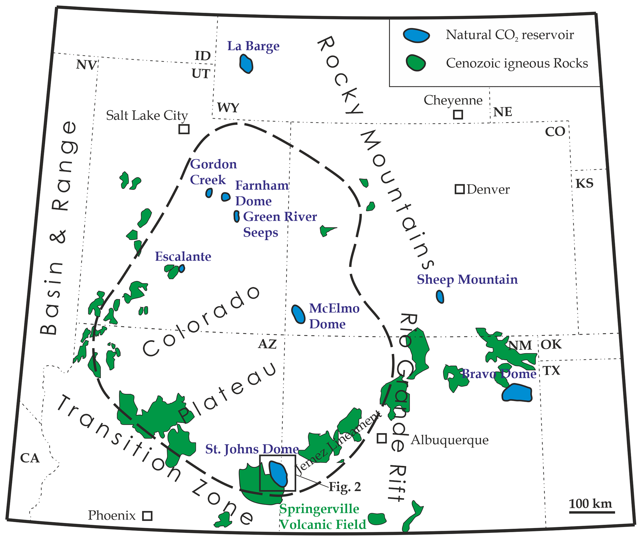
Figure 1Map showing the location of natural CO2 reservoirs and major late Cenozoic igneous rock occurrences on the Colorado Plateau and adjacent areas (after Aldrich and Laughlin, 1984; Bashir et al., 2011; Moore et al., 2005). The St. Johns Dome reservoir is located on the southern edge of the plateau, next to the Springerville volcanic field.
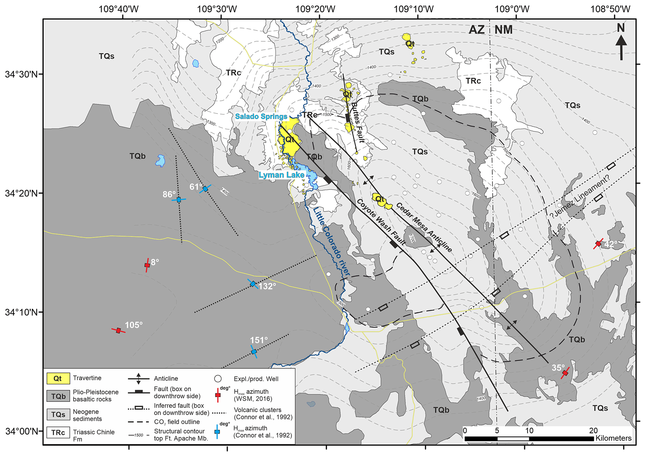
Figure 2Geological map of the St. Johns Dome natural CO2 reservoir showing the present-day extent of the CO2 reservoir, the location of the travertine deposits, orientation of the studied faults and the location of exploration and production wells used to build the subsurface model. Structural contours indicate the top of the Fort Apache Member and illustrate the faulted anticline setting. Stress field markers indicate the azimuth of maximum horizontal stress (SHmax) after the World Stress Map in red and from volcanic clusters in blue.
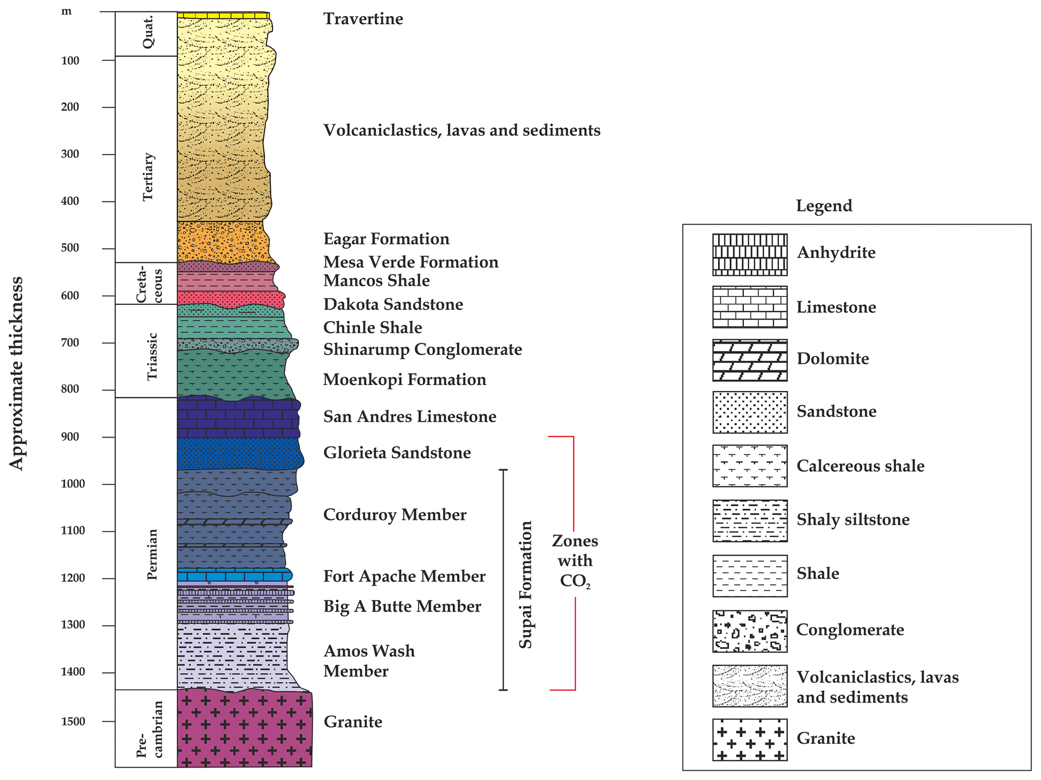
Figure 3Stratigraphic column of the St. Johns–Springerville area. Note that Cretaceous and younger deposits are often thinner than shown in this figure. CO2 accumulations occur in the Permian strata. After Rauzi (1999) and Embid (2009).
Expression and timing of fluid flow
The travertine deposits at St. Johns Dome are an expression of CO2-charged fluids migrating from the subsurface to the surface. Travertine formation occurs when CO2-rich fluids outgas CO2 as they migrate upwards to shallower depths and lower pressure, resulting in CaCO3 supersaturation and carbonate precipitation. As such, the St. Johns Dome travertine deposits cover a surface area of more than 30 km2, spread out over more than 300 km2 (Figs. 2 and 4), making them one of the greatest concentrations of travertine deposits in North America. Spatially, the travertine deposits are particularly concentrated in a 10 km long zone between Salado Springs and Lyman Lake (Fig. 4, Gilfillan et al., 2011; Moore et al., 2005). This area, where present-day travertine formation occurs (Priewisch et al., 2014), is bounded by the buried Coyote Wash Fault, and the distribution of the travertine deposits and active springs suggests that the local groundwater hydrology has been influenced by the Coyote Wash Fault (Embid, 2009). Analyses of surface springs, groundwater wells and CO2 wells with respect to the CO2 composition, water composition and noble gas concentrations have shown that samples taken along the Coyote Wash Fault trace are influenced by waters from depth that have been enriched in mantle-derived 3He and Ca (Gilfillan et al., 2014, 2011; Moore et al., 2005). Several modelling approaches emphasise the importance of the Coyote Wash Fault for CO2 and He migration from the Supai Formation to the surface (Allis et al., 2004; Keating et al., 2014) as, in all models, migration of gas to the surface occurs only if the fault forms a permeable conduit through the caprocks. Soil-flux measurements indicate that there is no diffuse CO2 leakage through the caprocks, suggesting instead that faults have controlled localised fluid flow (Allis et al., 2005). In addition to the occurrences along the NE tip of the Coyote Wash Fault (cluster A), travertine mounds follow the trace of the Buttes Fault, of which the subsurface extent is not well constrained, over a distance of more than 7 km (cluster B). Travertine mounds are also found NE of the present-day extent of the CO2 reservoir, with no clear link to other structural elements (cluster C). It is notable that there are no indications for fluid migration in the southern half of the reservoir.
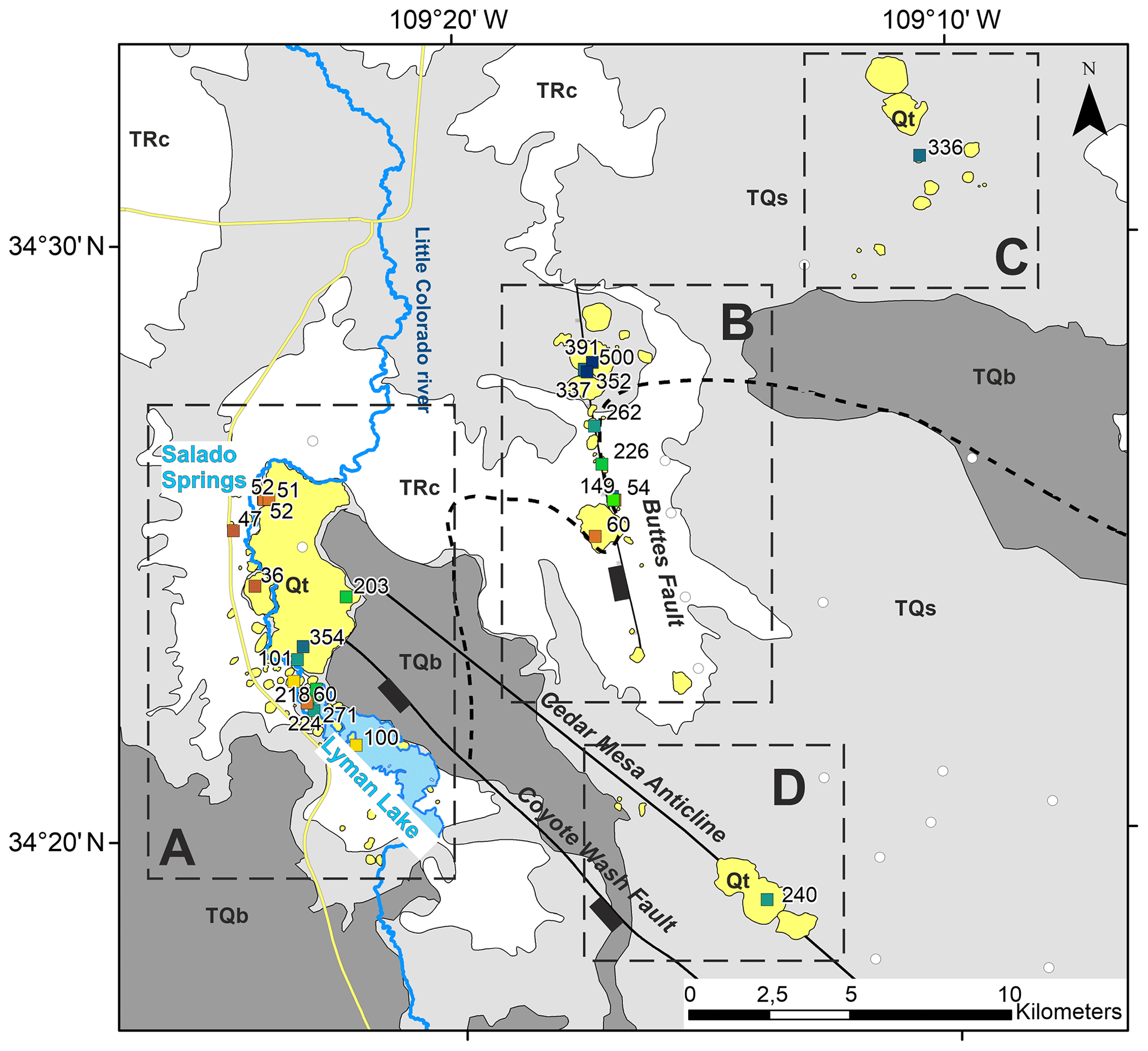
Figure 4Geological map illustrating the travertine deposits of the St. Johns Dome area. Coloured squares indicate available U–Th dating locations with respective ages in thousands of years (Miocic et al., 2019a; Priewisch et al., 2014); see Fig. 2 for legend. Four clusters of travertine mounds can be identified: cluster A, which spreads from Lyman Lake to Salado Springs, is at the tip of the Coyote Wash Fault; cluster B follows the trace of the Buttes Fault; cluster C is not related to a known structural feature and is located north of the present-day CO2 reservoir; and cluster D is located on the crest of the Cedar Mesa Anticline. Note that ages along the Buttes Fault (cluster B) generally get younger from north to south, whilst the travertines of cluster A show a wide range of ages without an obvious spatial correlation with age.
U-series dating of the travertine mounds shows that leakage of CO2 from the reservoir to the surface has occurred for at least 420 kyr (Fig. 4, Miocic et al., 2019a; Priewisch et al., 2014). Several of the samples analysed by Miocic et al. (2019a) fall outside the dating limitations of the U–Th method (∼500 kyr), which indicates that leakage may have occurred over much longer timescales. This is not surprising given the age of the Springerville volcanic field (earliest activity ∼9 Ma) from where the magmatic CO2 is almost certainly sourced. Individual seeps along the Buttes Fault have lifespans of up to 200 kyr and the massive travertine platform between Salado Springs and Lyman Lake has at least a similar lifetime. Volumetric calculations indicate that the subsurface reservoir is constantly or regularly recharged, as several times the volume of CO2 stored in the current reservoir has leaked in the past (Miocic et al., 2019a). However, due to the long timeframe of leakage recorded by the travertine deposits, only a very low percentage (0.1 %–0.001 %) of the reservoir volume (1900 Mt CO2) has leaked annually, and thus the site could still be seen as a suitable carbon storage site from a climate mitigation point of view (Miocic et al., 2019a).
These observations illustrate that fluid migration at the St. Johns Dome occurs along fault zones, and once migration pathways have been established they are spatially fixed for long periods (>100 kyr). This is in contrast to other fault-controlled fluid migration pathways on the Colorado Plateau, for which it is suggested that these stay open only episodically for a few thousand years after rapid fault movement and subsequently heal (Frery et al., 2015). Similar cyclic reopening and healing of fractures governing fault zone permeability have been recorded by travertine deposition at other active fault zones in Italy (Brogi et al., 2010). Spatially and temporally fixed migration pathways are concerning for subsurface storage sites, and thus the processes controlling vertical fault zone permeability at the St. Johns Dome are analysed herein.
In order to investigate the mechanisms governing the vertical fluid flow at the St. Johns Dome, a geomechanical analysis of the Coyote Wash Fault was conducted using slip tendency and fracture stability approaches. Slip tendency (Ts) is a method that allows for a fast assessment of the relative tendency of a fault surface to undergo slip under the present-state effective stress field. It is the ratio of resolved shear stress to resolved normal stress on a surface (Morris et al., 1996):
where τ is the shear stress and σn the effective normal stress acting on the fault. Slip is considered likely to occur on a surface if Ts≥μs, with μs being the coefficient of static friction which is generally assumed to be 0.6 (Byerlee, 1978; Moeck et al., 2009; Sibson, 2003). Thus, using this assumption, Ts predicts slip is more likely when the friction coefficient is exceeded but does not explicitly require fault properties to be input to model (simply requiring the normal and shear stresses and an assumed coefficient of friction). Fracture stability (Fs) is the increase in pore pressure that is required to reduce the effective stresses such that a fault plane is forced into shear, tensile or hybrid failure (Handin et al., 1963; Terzaghi, 1923). Therefore, failure envelopes must be explicitly considered to model Fs which requires inputting known rock properties such as cohesion and angle of internal friction and hence fault rock composition to model.
A 3-D geological model of the St. Johns Dome was built based on published geological maps (Embid, 2009; Sirrine, 1958), well data from 37 exploration and production wells available from the Arizona oil and gas conservation commission (well logs, horizon markers) and previously published reservoir horizon map and markers (Rauzi, 1999) using Move™. Between wells, a constant stratigraphic thickness was assumed, and for the fault a dip of 70∘ was estimated, based on previous works (Embid, 2009; Rauzi, 1999) and a 3-D dip-domain construction (Fernandez et al., 2008) of the intersection of the fault trace with the 1∕3 arcsec DEM of the 3-D elevation programme of the United States Geological Survey (USGS). The modelled fault has 6635 faces constructed as triangles from 3525 vertices. Cut-off lines were created on the fault surface by extracting the dip from a 200 m wide patch of the horizon of interest on either side of the fault and projecting this along the dip direction until it intersected with the fault (Yielding and Freeman, 2016). The current gas–water contact is at 1494 m a.s.l. (Rauzi, 1999) and is assumed to be horizontal. Due to lack of pressure data, a hydrostatic pressure gradient is assumed (0.0105 MPa m−1). Geomechanical analysis of the model was conducted with industry standard software (Move™ and TrapTester®). As no outcropping fault rocks were available, the shale gouge ratio (SGR; Yielding et al., 1997) was used as a fault rock proxy. SGR was calculated from a Vshale log of well 10-29-31, which was calculated from the gamma ray log assuming a linear response (Asquith and Krygowski, 2004). As this method only applies to siliciclastic rocks, zonal Vshale values for evaporitic sequences – 70 % shale content for anhydrite and 55 % shale for carbonates were assumed, expecting rapid fault sealing for these lithologies (Pluymakers and Spiers, 2014), or low-permeability fault rocks (Michie et al., 2018) – were used. Resulting SGR values indicate a high potential of phyllosilicate-rich fault rocks (Fig. 5). To emphasise the uncertainty regarding the fault rock composition, two different fault rocks were used for Fs calculations: a low-friction fault rock (cohesion C=0.5 MPa; coefficient of internal friction μ=0.45) and high-friction fault rock (C=0.5, μ=0.6) with rock strength values from the TrapTester® internal database. Note that, for modelling purposes, we assume a siliciclastic sequence; however, the stratigraphic sequence also contains ∼15 % carbonate and evaporitic rocks (Fig. 3) which may have locally significant influence on the fault rock strength. Ts results are presented using stereonets, as this allows the reader to visualise how changes in the stress field orientation would influence fault stability, while Fs results are presented on a Mohr circle, as this allows a direct visualisation of how much the pore pressure needs to change to force different parts of the fault into failure. It also allows the reader to see how changes in fault rock strength could change the pore pressure needed for fault failure. For stress field data, no in situ stress measurements from the gas field itself were available; however, in addition to World Stress Map data (Heidbach et al., 2016), the nearby Springerville volcanic field can be used to derive the orientation of the horizontal stresses as presented in the following.
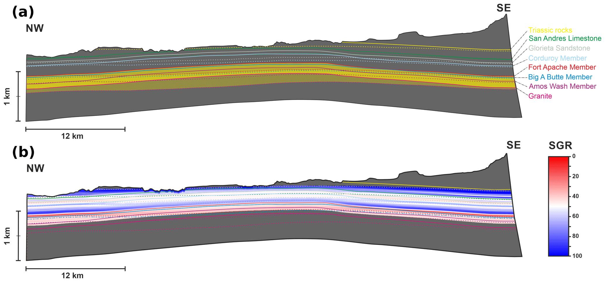
Figure 5(a) Allan diagram (Allan, 1989) of the Coyote Wash Fault: dashed lines represent the hangingwall; straight lines represent footwall cut-off lines. Yellow-coloured horizons are the main reservoirs (Amos Wash Member, Big A Butte Member and Fort Apache Member of the Permian Supai Formation). (b) Shale gouge ratio plotted onto the Coyote Wash Fault plane. SGR indicates that for most of the fault phyllosilicate-rich fault rocks are likely (SGR > 30).
Stress field at the St. Johns Dome
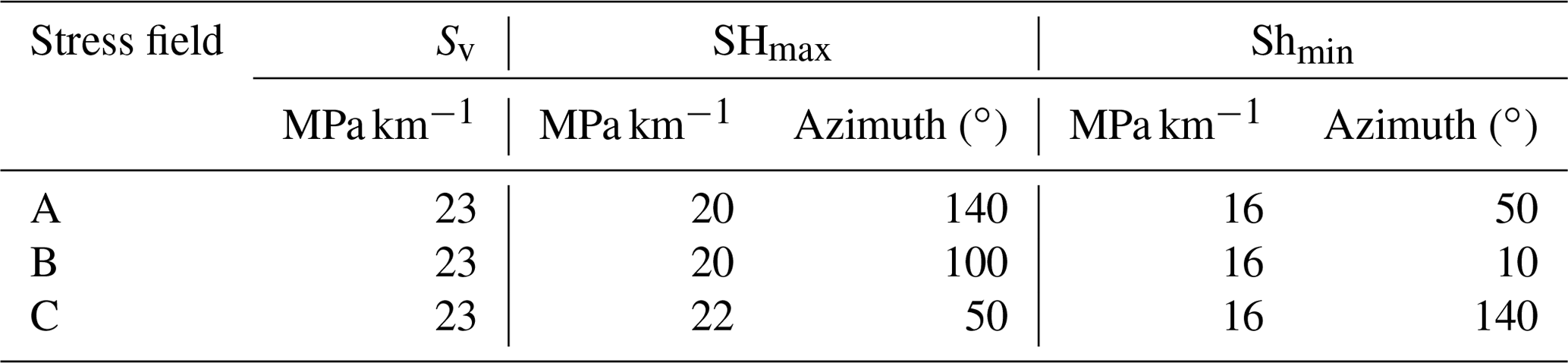
The location of the St. Johns Dome reservoir at the margin of the Colorado Plateau and within the greater Basin and Range province has significant impact on the stress field in the study area. It is clear that the regional stress field is highly variable, as shown by the available stress field data in the vicinity of the St. Johns Dome (50 km radius, Fig. 2) from the World Stress Map (Heidbach et al., 2016) combined with a regional study on volcanic vent orientation in the Springerville volcanic field (Table 1, Connor et al., 1992). Note that the maximum horizontal stress (SHmax) from Connor et al. (1992) is based on vent clusters linearly aligned with lengths of 11 to 20 km length (Fig. 2), and that Table 1 lists them as point measurements at the centre of the cluster. To the south and southeast of the CO2 field, the SHmax is oriented NE–SW, while west of the reservoir the SHmax orientation is highly variable, ranging from NW–SE to E–W (Fig. 2). While these data points are associated with an uncertainty of at least ±15∘, the orientation of the stress field for the St. Johns Dome faults is difficult to constrain. A normal faulting regime (vertical stress (Sv) > maximum horizontal stress (SHmax) > minimum horizontal stress (Shmin)) is assumed as based on the World Stress Map and works by Kreemer et al. (2010) and Wong and Humphrey (1989) for this area of the Colorado Plateau. Integration of density logs (wells 10-29-31 and 11-16-30) gives a magnitude of Sv of 23 MPa km−1. Minimal horizontal stress in normal faulting regimes is typically about 65 %–85 % of the vertical stress (Hillis, 2003), which gives a magnitude of Shmin in the range of 15 to 19.5 MPa with the magnitude of SHmax set between Sv and Shmin.
Table 1Table listing published stress field indicators around the St. Johns Dome. They form three clusters: IDs 2–4; 5 and 6; 7 and 8. WSM is the World Stress Map.
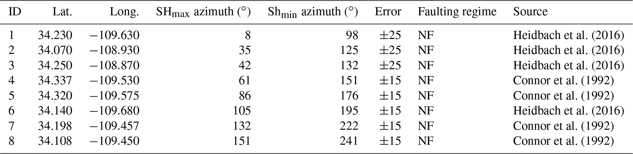
As the reported stress field measurements appear to form three clusters (Table 1), three different stress fields were defined (Table 2): stress field A is similar to the stress fields indicated by measurements 7 and 8, with SHmax having an azimuth of 140∘; stress field B is oriented similar to the stress field measurements 5 and 6 with a SHmax azimuth of 100∘; and stress field C is similar to the stress fields indicated by measurements 2 to 4 with a SHmax azimuth of 50∘. The solitary north–south stress field measurement (ID 1) was not considered further. For the ∼ NW–SE-trending Coyote Wash Fault, these stress fields also represent the most likely (A), moderately likely (B) and least likely (C) cases for fault reactivation. Geomechanical analysis was conducted under all three defined stress fields.
The results of the geomechanical analysis of the Coyote Wash Fault highlight that the orientation of the stress field has a major impact on both the slip tendency (Fig. 6) and fracture stability (Fig. 7). Slip tendency indicates that for stress field A most parts of the fault are close to failure (Ts>0.5); for stress field B, the fault is only intermediately stressed (); and for stress field C, the fault is far away from failure (Ts<0.2). Similarly, only slight increases of pore pressure are needed to force the fault into failure under stress fields A and B and a low-friction fault rock (0.95 and 1.33 MPa, respectively). The pore pressure increase needed to force the fault into failure in the case of stress field C is much higher at 6.21 MPa. Note that slip tendency in both stress fields (A and B) is higher at the NW tip of the fault than in the SE section of the fault (Fig. 6), indicating that failure is more likely to occur in the NW. This is also true for the spatial distribution of fracture stability which, for stress fields A and C (most and least likely to fail) and a low-friction fault rock, is illustrated in Fig. 7.
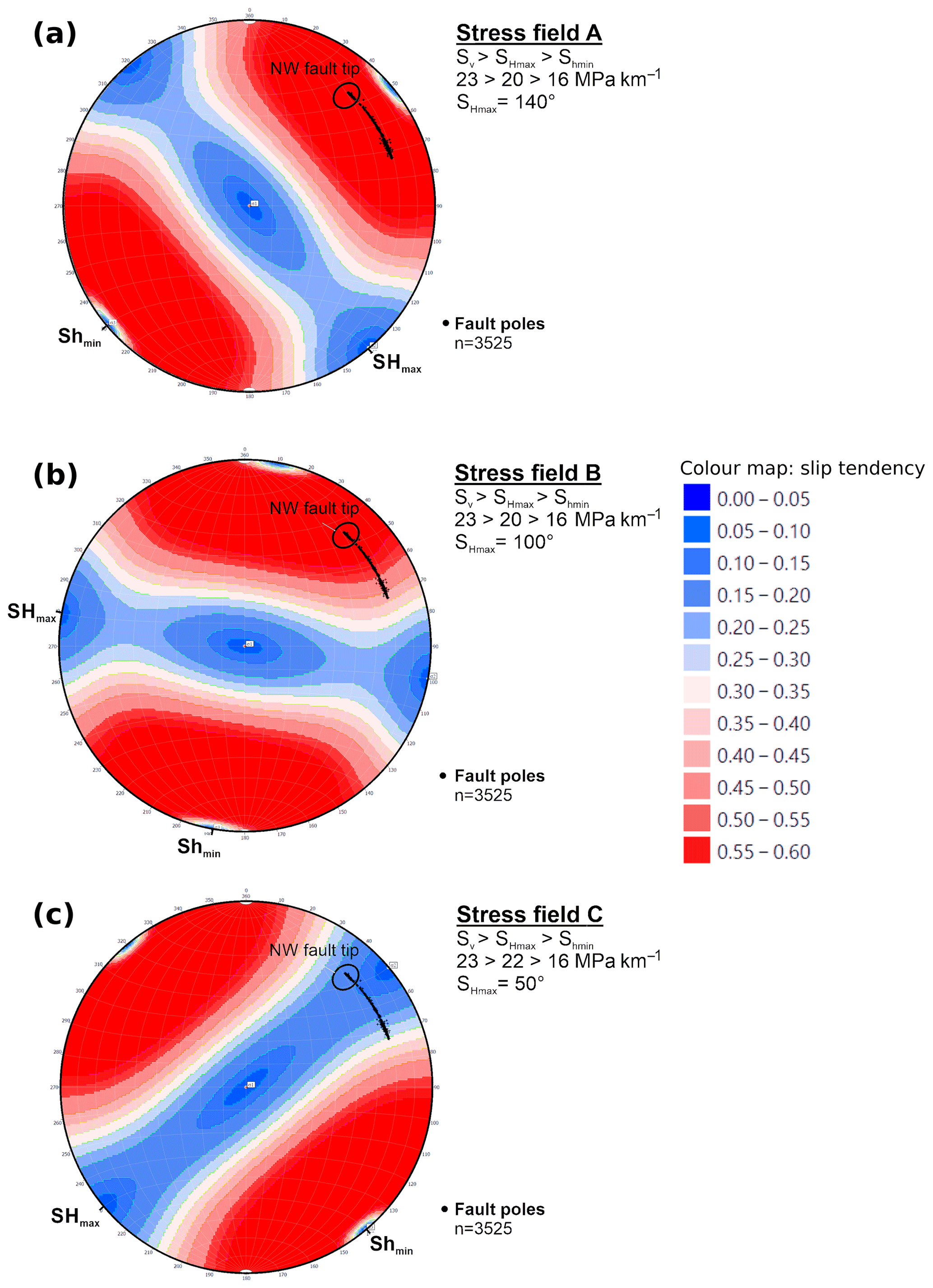
Figure 6Stereoplots illustrating the slip tendency for the Coyote Wash Fault (black dots) for the three different stress fields. The fault is at least partly close to failure for stress fields A and B, while stress field C results in very low slip tendencies. Particularly the NW fault tip (indicated on the stereoplots) where travertine deposits are found at the surface is close to failure.
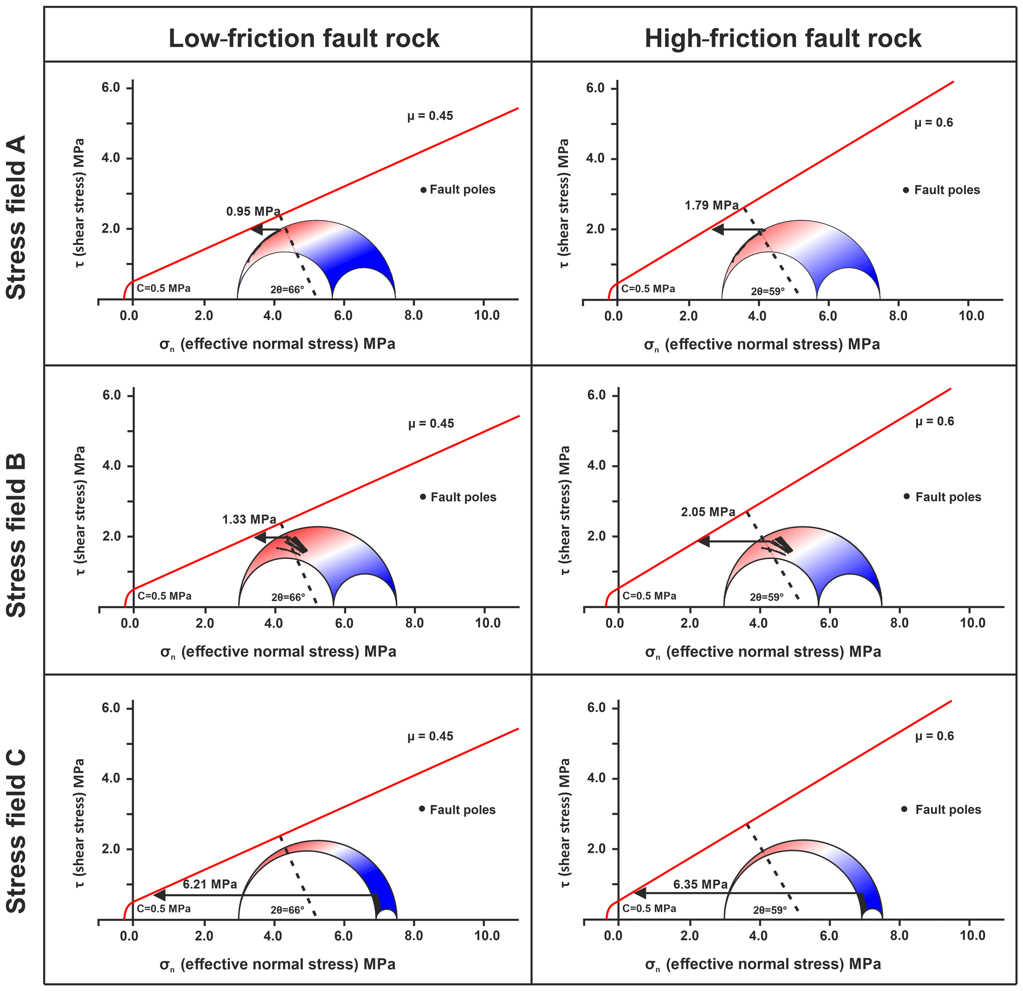
Figure 7Mohr diagrams illustrating the fracture stability for the Coyote Wash Fault within the three stress fields for two types of fault rocks. Black arrows indicate the increase in pore pressure needed to force the fault into failure. Number of fault poles in each plot is 3525.
The results of the geomechanical analysis show that the bounding fault of the St. Johns Dome CO2 reservoir is intermediately to critically stressed for two of the three modelled stress fields (A and B). For the same stress fields, a low-friction fault rock within the Coyote Wash Fault zone results in fracture stabilities which range from less than 1 to 1.33 MPa. The most critically stressed areas are located at the NW tip of the fault (Salado Springs), while the SE part of the fault is relatively stable for all studied stress fields.
The Fs values of 0.95 and 1.33 MPa for low-friction fault rock translate to an additional CO2 column of ∼110 and ∼160 m, respectively. Currently, the reservoir is not filled to spill and the 3-D geological model indicates that the reservoir interval at the NW part of the fault could retain an additional ∼150 m of CO2 column. Whilst a fault does not need to be critically stressed to be hydraulically conductive, the additional filling of the reservoir with a third to half more CO2 by volume could potentially lead to fault failure and vertical fluid migration along the fault. Evidence that the reservoir has held more CO2 in the past is provided by older travertine deposits located outside the present-day extent of the subsurface reservoir (Figs. 2 and 4; Miocic et al., 2019a) and the fact that higher paleoreservoir pressures have been implied by a geochemical study (Moore et al., 2005). These higher reservoir pressures were likely enough to bring the NW part of the fault close to failure, and we suggest that the permeability of fracture networks within the critically stressed fault damage zone was therefore increased (Barton et al., 1995; Ito and Zoback, 2000; Min et al., 2004). In order to sustain the long periods of leakage recorded by the spatially stable travertine deposition, the fault must be critically stressed for similarly long periods. Indeed, volume calculations of how much CO2 must have leaked to the surface based on the travertine deposits show that 1–2 orders of magnitude more CO2 was lost from the reservoir than it can hold (Miocic et al., 2019a). It is suggested that the continuous influx of magmatic CO2 degassing from beneath the Springerville volcanic field into the reservoir caused the fault to be close to being critically stressed – a reasoning also supported by this study.
The geomechanical analysis also demonstrates that a change of the fault orientation within the stress field should not be underestimated and can lead to failure along one part of a fault, while large parts of the fault are geomechanically stable. The strike direction of the Coyote Wash Fault changes from ESE–WNW in the southern part of the fault to NW–SE in the northern section, and this change in strike is enough to render the northern section critically stressed (in two of the stress fields modelled: A and B) – with leakage pathways being the result (Fig. 9). Higher paleo gas columns within the reservoir likely contributed the forcing the fault into failure at the northern fault tip. However, some sections of the fault in the SE also have relatively low fracture stability values (Fig. 8a) which translate to only tens of metres more supported gas column than the NW section. Yet, there are no indications for past or present leakage in the SE part of the St. Johns Dome. We argue that the stress field orientation in the SE is different from the stress field orientation in the NW area of the St. Johns Dome and that as a result the fault is far from failure towards its SE tip. This is supported by stress field measurements in the vicinity of the southern edge of the reservoir (Fig. 2, Table 1), which imply a NE–SW SHmax orientation.
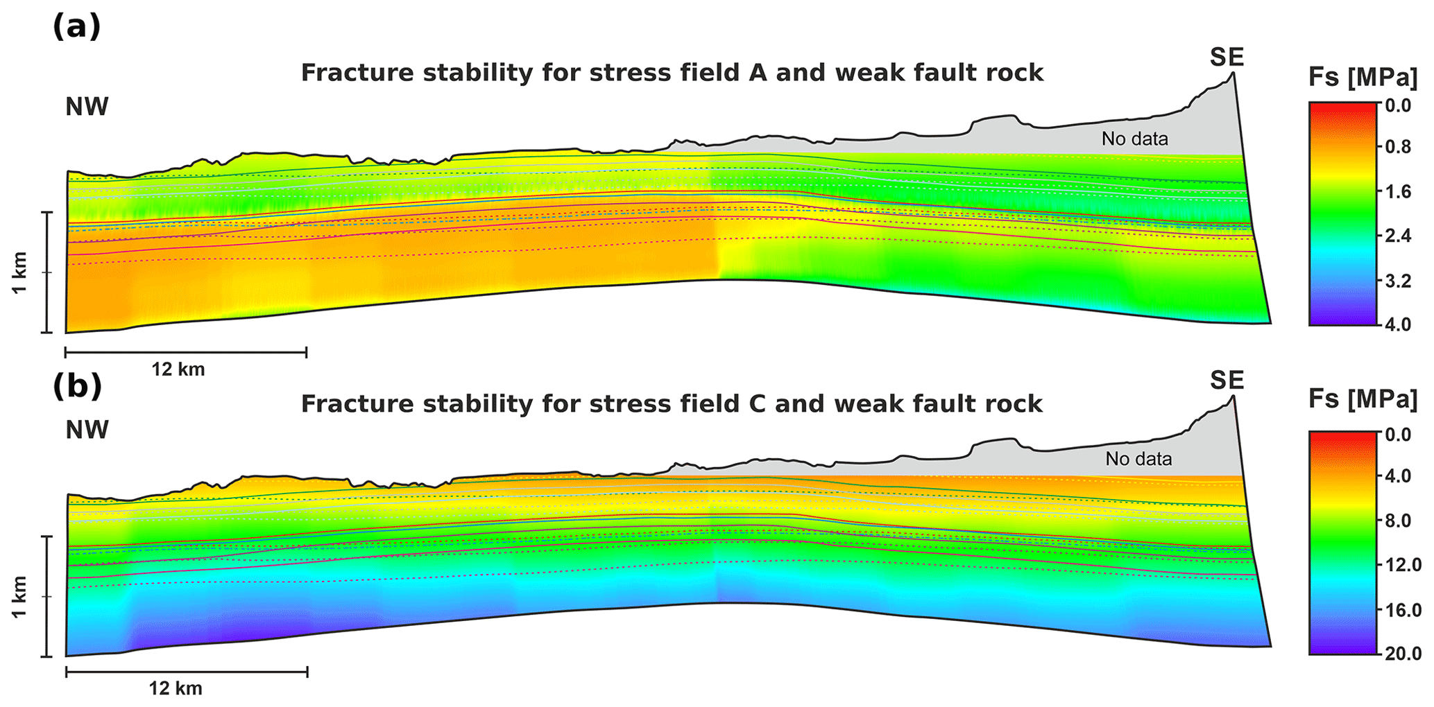
Figure 8Fracture stability plotted onto the Coyote Wash Fault surface for (a) stress field A and a low-friction fault rock and (b) stress field C and a low-friction fault rock. Note the differences in the colour scale. Fs is more critical in the NW part of the fault for stress field A, while Fs for stress field C is far from critical. Dashed lines represent the hangingwall, and straight lines represent the footwall cut-off lines; see Fig. 5 for stratigraphic context.
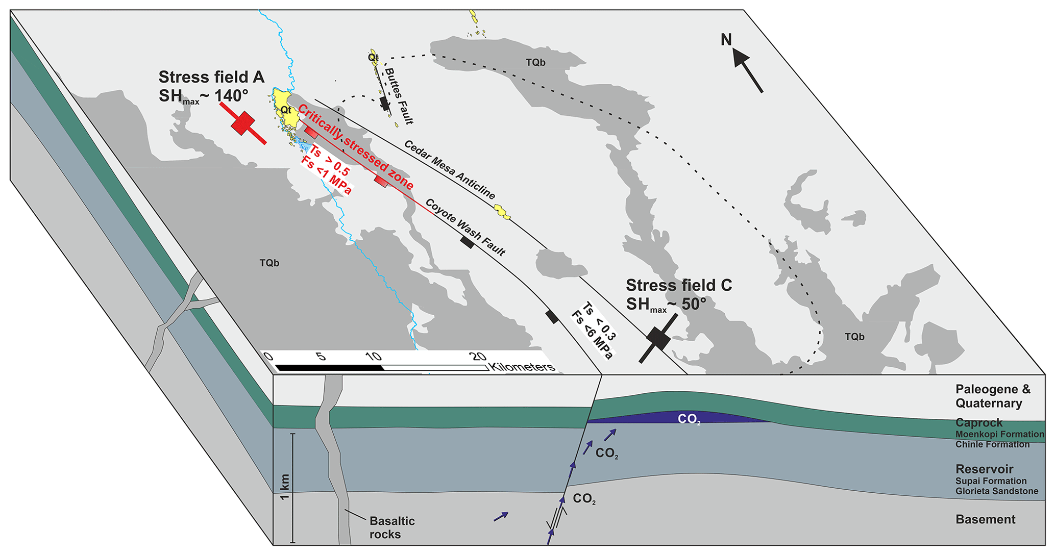
Figure 9Block diagram illustrating the geological setting of the St. Johns Dome area. The fault-bound CO2 reservoir has been filled with CO2 from depth, and leakage of CO2 from the reservoir to the surface occurs at the NW tip of the Coyote Wash Fault. The leakage is geomechanically controlled as the stress field orientation changes along the strike of the fault as well as the strike direction of the fault. At the NW tip of the fault slip, stability values of >0.5 and fracture stability of less than 1 MPa indicate a critically stressed fault. See Fig. 2 for a complete legend, vertical exaggeration.
Vertical migration of fluids through fault and fracture networks or corridors can be classified by their location in (1) the fault damage zone, (2) at the fault tip and (3) at the crest of a fold (Ogata et al., 2014). As evidenced by travertine deposits, vertical fluid migration at the St. Johns Dome occurred at all three types of fracture networks (Fig. 2), but considerably larger volumes of fluid migrated through fracture networks linked to faults, particular at their NW tips. This indicates that, at least at this site, faults are a higher risk factor for leakage than other migration pathways such as fracture networks along the anticline structure or capillary leakage though a caprock. Based on travertine volumes, the largest volumes of leakage occurred at the NW tip of the Coyote Wash Fault, in the area between Lyman Lake and Salado Springs (Figs. 2, 4; Miocic et al., 2019a). This indicates high-permeability fracture networks within the damage zone close to the fault tip as predicted by numerical models (Backers and Moeck, 2015; Zhang et al., 2008). The lack of similar leakage pathways observed at the SE tip of the fault can be attributed to the different stress field orientation. For geological storage, in general, the occurrence of large-scale leakage at fault tips is also concerning, as displacement at fault tips usually is low and as such fault tips are not seismically resolvable and may remain undetected. Thus, seismically resolved faults could be extended beyond the normally picked extent to include the fault tips. Similarly, faults with low displacement such as the Buttes Fault, for which significant fault-related leakage has been recorded but is thought to have a maximum displacement of <25 m, may not be detectable on seismic data. This highlights the need for a good structural understanding of any geological storage site to ensure that fault tips and small faults are considered and incorporated, possibly as an additional uncertainty parameter, into the geological model.
While the geomechanical analysis highlights the role of critically stressed faults for fluid migration at the St. Johns Dome, it is missing in situ stress field data from within the CO2 reservoir. Such data are crucial for a detailed and reliable study of fracture and fault stability (e.g. Becker et al., 2019); however, there are cases where such in situ data are missing and a geomechanical analysis may be needed (Henk, 2005). In particular, during the site selection and appraisal of subsurface storage sites, a preliminary geomechanical analysis based on existing stress field data can identify potentially critically stressed faults. The lack of in situ data can be compensated by studying several plausible stress fields (as in this study) and including uncertainties into the geomechanical analysis (Ziegler and Heidbach, 2020). For the latter, uncertainties in the stress field orientation and magnitude and in the fault orientation should be included. Statistical approaches such as Bayesian or Markov chain Monte Carlo modelling can be useful to identify uncertainty thresholds and to determine the precision by which the geomechanical parameters need to be known in order to have reliable fault and fracture stability predictions (Bao et al., 2013; Chiaramonte et al., 2008; McFarland et al., 2012).
For the geomechanical prediction of permeable fracture networks, and thus leakage pathways at the St. Johns Dome, the stress field orientation is integral. The location of the natural CO2 reservoir at the edge of the Colorado Plateau is the likely reason for the stress field orientation change, with clear changes in crustal composition and strength in the vicinity of the St. Johns Dome (Hendricks and Plescia, 1991; Qashqai et al., 2016). The study area is also located at the intersection of the NE–NNE-trending Jemez lineament, a tectonically active zone that is characterised by Paleogene–Quaternary extension and volcanism (Fig. 1), and the ESE-trending Arizona Transition Zone (Aldrich and Laughlin, 1984; Kreemer et al., 2010). Additionally, the presence of salt deposits in the Holbrook Basin north of the study area may also impact the local stress field (Neal and Colpitts, 1997; Rauzi, 2000). The complex regional setting at the St. Johns Dome and the associated uncertainties for geomechanical modelling further highlight the need for thorough site selection criteria for engineered fluid storage sites and adequate geological data to ensure that only reservoirs with well-understood structural frameworks are chosen.
Geomechanical modelling suggests that vertical fluid migration from the reservoir to the surface at the St. Johns Dome natural CO2 reservoir is controlled by fracture networks in the damage zone and tip of near-critically stressed faults. We propose that regular filling of the reservoir with CO2 from mantle sources increased the pore pressure within the reservoir and further reduced the stability of near critically stressed faults, leading to the leakage of large volumes of CO2 over the time span of several hundred thousand years. While the leakage rates at the St. Johns Dome are low enough to render the faulted site an adequate CO2 store for climate mitigation, similar leakage rates could impede geological storage of methane or hydrogen, particularly at onshore storage sites, based on socially and operationally acceptable criteria.
For fault-bound subsurface storage sites for CO2 or other fluids, the history of geomechanically controlled leakage at the St. Johns Dome clearly illustrates the need for a good understanding of regional and local stress fields and faults. In particular, the stress state of faults and fault-related fracture networks prior to fluid injection needs to be well understood in order to reduce the risk of vertical fluid migration through fractured caprock. We recommended to select areas where there are no significant regional stress field changes, as these complicate geomechanical predictions. Indeed, in situ stress data from wells are key for any advanced leakage risk prognosis. To further understand the leakage mechanisms at the St. Johns Dome, geomechanical modelling of the Buttes Fault, combined with an uncertainty assessment, is recommended. More detailed dating of the travertine deposits could reveal at which part of the faults (fault tip vs. fault damage zone) failure occurred first and provide insights into the time dynamics of leakage.
The 3-D model is available from the corresponding author upon request.
JMM and SMVG designed the research project which was carried out by JMM with help from GJ and input from SMVG. JMM prepared the manuscript with contributions from all co-authors.
The authors declare that they have no conflict of interest.
This article is part of the special issue “Faults, fractures, and fluid flow in the shallow crust”. It is not associated with a conference.
We thank Badley Geoscience Limited for providing an educational licence of TrapTester® and Petroleum Experts/Midland Valley for providing an educational licence of Move™. The paper greatly benefited from constructive reviews by Alan Morris and Johnathon Osmond as well as a short comment by Mark Mulrooney.
Johannes M. Miocic was partly supported by the European Commission, Seventh Framework Programme (PANACEA; grant no. 282900); Gareth Johnson was supported by EPSRC grant EP/P026214/1 and University of Strathclyde Faculty of Engineering; and Stuart M. V. Gilfillan was partly supported by NERC fellowship NE/G015163/1, NERC grant NE/L008475/1 and EPSRC grants EP/P026214/1, EP/K036033/1 and EP/K000446/1. The article processing charge was funded by the Baden-Wuerttemberg Ministry of Science, Research and Art and the University of Freiburg in the funding programme Open Access Publishing.
This paper was edited by Peter Eichhubl and reviewed by Alan Morris and Johnathon Osmond.
Alcalde, J., Flude, S., Wilkinson, M., Johnson, G., Edlmann, K., Bond, C. E., Scott, V., Gilfillan, S. M. V., Ogaya, X., and Haszeldine, R. S.: Estimating geological CO2 storage security to deliver on climate mitigation, Nat. Commun., 9, 2201, https://doi.org/10.1038/s41467-018-04423-1, 2018.
Aldrich, M. J. and Laughlin, A. W.: A model for the tectonic development of the Southeastern Colorado Plateau Boundary, J. Geophys. Res.-Sol. Ea., 89, 10207–10218, https://doi.org/10.1029/JB089iB12p10207, 1984.
Allan, U. S.: Model for hydrocarbon migration and entrapment within faulted structures, AAPG Bull., 73, 803–811, 1989.
Allis, R., Bergfeld, D., Moore, J., McClure, K., Morgan, C., Chidsey, T., Heath, J., and McPherson, B.: Implications of results from CO2 flux surveys over known CO2 systems for long-term monitoring, in: Fourth Annual Conference on Carbon Capture and Sequestration, DOE/NETL, Alexandria, Virginia, USA, 2005.
Allis, R. G., Moore, J., and White, S. P.: Reactive Multiphase behavior of CO2 in Saline Aquifers beneath the Colorado Plateau, Quaterly Technical Report, University of Utah, Salt Lake City, 2004.
Asquith, G. B. and Krygowski, D.: Basic Well Log Analysis, 2nd Edn., AAPG, Tulsa, OK, USA, 2004.
Backers, T. and Moeck, I.: Fault tips as favorable drilling targets for geothermal prospecting – a fracture mechanical perspective, International Society for Rock Mechanics and Rock Engineering, Salzburg, Austria, 2015.
Bao, J., Xu, Z., Lin, G., and Fang, Y.: Evaluating the impact of aquifer layer properties on geomechanical response during CO2 geological sequestration, Comput. Geosci., 54, 28–37, https://doi.org/10.1016/j.cageo.2013.01.015, 2013.
Barton, C. A., Zoback, M. D., and Moos, D.: Fluid flow along potentially active faults in crystalline rock, Geology, 23, 683–686, https://doi.org/10.1130/0091-7613(1995)023<0683:FFAPAF>2.3.CO;2, 1995.
Bashir, L., Gao, S. S., Liu, K. H., and Mickus, K.: Crustal structure and evolution beneath the Colorado Plateau and the southern Basin and Range Province: Results from receiver function and gravity studies, Geochem. Geophy. Geosy., 12, Q06008, https://doi.org/10.1029/2011GC003563, 2011.
Becker, I., Müller, B., Bastian, K., Jelinek, W., and Hilgers, C.: Present-day stress control on fluid migration pathways: Case study of the Zechstein fractured carbonates, NW-Germany – ScienceDirect, Mar. Petrol. Geol., 103, 320–330, https://doi.org/10.1016/j.marpetgeo.2019.03.002, 2019.
Bond, C. E., Wightman, R., and Ringrose, P. S.: The influence of fracture anisotropy on CO2 flow, Geophys. Res. Lett., 40, 1284–1289, https://doi.org/10.1002/grl.50313, 2013.
Bond, C. E., Kremer, Y., Johnson, G., Hicks, N., Lister, R., Jones, D. G., Haszeldine, R. S., Saunders, I., Gilfillan, S. M. V., Shipton, Z. K., and Pearce, J.: The physical characteristics of a CO2 seeping fault: The implications of fracture permeability for carbon capture and storage integrity, Int. J. Greenh. Gas Con., 61, 49–60, https://doi.org/10.1016/j.ijggc.2017.01.015, 2017.
Brogi, A., Capezzuoli, E., Aqué, R., Branca, M., and Voltaggio, M.: Studying travertines for neotectonics investigations: Middle–Late Pleistocene syn-tectonic travertine deposition at Serre di Rapolano (Northern Apennines, Italy), Int. J. Earth Sci. (Geol. Rundsch.), 99, 1383–1398, https://doi.org/10.1007/s00531-009-0456-y, 2010.
Burnside, N. M., Shipton, Z. K., Dockrill, B., and Ellam, R. M.: Man-made versus natural CO2 leakage: A 400 k.y. history of an analogue for engineered geological storage of CO2, Geology, 41, 471–474, https://doi.org/10.1130/G33738.1, 2013.
Byerlee, J.: Friction of rocks, PAGEOPH, 116, 615–626, https://doi.org/10.1007/BF00876528, 1978.
Caillet, G.: The caprock of the Snorre Field, Norway: a possible leakage by hydraulic fracturing, Mar. Petrol. Geol., 10, 42–50, https://doi.org/10.1016/0264-8172(93)90098-D, 1993.
Caine, J. S., Evans, J. P., and Forster, C. B.: Fault zone architecture and permeability structure, Geology, 24, 1025–1028, 1996.
Cappa, F.: Modelling fluid transfer and slip in a fault zone when integrating heterogeneous hydromechanical characteristics in its internal structure, Geophys. J. Int., 178, 1357–1362, https://doi.org/10.1111/j.1365-246X.2009.04291.x, 2009.
Cavanagh, A. J., Haszeldine, R. S., and Nazarian, B.: The Sleipner CO2 storage site: using a basin model to understand reservoir simulations of plume dynamics, First Break, 33, 61–68, 2015.
Chadwick, A., Arts, R., Bernstone, C., May, F., Thibeau, S., and Zweigel, P.: Best practice for the storage of CO2 in saline aquifers – observations and guidelines from the SACS and CO2STORE projects, British Geological Survey, Nottingham, UK, 2008.
Chester, F. M. and Logan, J. M.: Implications for mechanical properties of brittle faults from observations of the Punchbowl fault zone, California, PAGEOPH, 124, 79–106, https://doi.org/10.1007/BF00875720, 1986.
Chiaramonte, L., Zoback, M. D., Friedmann, J., and Stamp, V.: Seal integrity and feasibility of CO2 sequestration in the Teapot Dome EOR pilot: geomechanical site characterization, Environ. Geol., 54, 1667–1675, https://doi.org/10.1007/s00254-007-0948-7, 2008.
Choi, J.-H., Edwards, P., Ko, K., and Kim, Y.-S.: Definition and classification of fault damage zones: A review and a new methodological approach, Earth-Sci. Rev., 152, 70–87, https://doi.org/10.1016/j.earscirev.2015.11.006, 2016.
Condit, C. D. and Connor, C. B.: Recurrence rates of volcanism in basaltic volcanic fields: An example from the Springerville volcanic field, Arizona, Geol. Soc. Am. Bull., 108, 1225–1241, https://doi.org/10.1130/0016-7606(1996)108<1225:RROVIB>2.3.CO;2, 1996.
Condit, C. D., Crumpler, L. S., and Aubele, J. C.: Lithologic, age group, magnetopolarity, and geochemical maps of the Springerville Volcanic Field, East-Central Arizona, U.S. Dept. of the Interior, U.S. Geological Survey, 1993.
Connor, C. B., Condit, C. D., Crumpler, L. S., and Aubele, J. C.: Evidence of regional structural controls on vent distribution: Springerville Volcanic Field, Arizona, J. Geophys. Res., 97, 12349–12359, https://doi.org/10.1029/92JB00929, 1992.
Crumpler, L. S., Aubele, J. C., and Condit, C. D.: Volcanics and neotectoniccharacteristics of the Springerville volcanic field, Arizona, in: New Mexico Geological Society Guidebook, 45th Field Conference, edited by: Chamberlin, R. M., Kues, B. S., Cather, S. M., Barker, J. M., and McIntosh, W. C., New Mexico Geological Society, Scorro, New Mexico, USA, 147–164, 1994.
Davatzes, N. C. and Aydin, A.: Distribution and nature of fault architecture in a layered sandstone and shale sequence: An example from the Moab fault, Utah, AAPG Memoir., 85, 153–180, 2005.
Dockrill, B. and Shipton, Z. K.: Structural controls on leakage from a natural CO2 geologic storage site: Central Utah, U.S.A, J. Struct. Geol., 32, 1768–1782, https://doi.org/10.1016/j.jsg.2010.01.007, 2010.
Eichhubl, P., Davatz, N. C., and Becker, S. P.: Structural and diagenetic control of fluid migration and cementation along the Moab fault, Utah, AAPG Bull., 93, 653–681, https://doi.org/10.1306/02180908080, 2009.
Embid, E. H.: U-series dating, geochemistry, and geomorphic studies of travertines and springs of the Springerville area, east-central Arizona, and tectonic implications, MSc thesis, The University of New Mexico, Albuquerque, 2009.
Faulkner, D. R. and Rutter, E. H.: Can the maintenance of overpressured fluids in large strike-slip fault zones explain their apparent weakness?, Geology, 29, 503–506, https://doi.org/10.1130/0091-7613(2001)029<0503:CTMOOF>2.0.CO;2, 2001.
Faulkner, D. R., Lewis, A. C., and Rutter, E. H.: On the internal structure and mechanics of large strike-slip fault zones: field observations of the Carboneras fault in southeastern Spain, Tectonophysics, 367, 235–251, https://doi.org/10.1016/S0040-1951(03)00134-3, 2003.
Faulkner, D. R., Jackson, C. A. L., Lunn, R. J., Schlische, R. W., Shipton, Z. K., Wibberley, C. A. J., and Withjack, M. O.: A review of recent developments concerning the structure, mechanics and fluid flow properties of fault zones, J. Struct. Geol., 32, 1557–1575, https://doi.org/10.1016/j.jsg.2010.06.009, 2010.
Fernandez, O., Jones, S., Armstrong, N., Johnson, G., Ravaglia, A., and Muñoz, J. A.: Automated tools within workflows for 3D structural construction from surface and subsurface data, Geoinformatica, 13, 291, https://doi.org/10.1007/s10707-008-0059-y, 2008.
Frery, E., Gratier, J.-P., Ellouz-Zimmerman, N., Loiselet, C., Braun, J., Deschamps, P., Blamart, D., Hamelin, B., and Swennen, R.: Evolution of fault permeability during episodic fluid circulation: Evidence for the effects of fluid–rock interactions from travertine studies (Utah–USA), Tectonophysics, 651–652, 121–137, https://doi.org/10.1016/j.tecto.2015.03.018, 2015.
Gilfillan, S., Haszedline, S., Stuart, F., Gyore, D., Kilgallon, R., and Wilkinson, M.: The application of noble gases and carbon stable isotopes in tracing the fate, migration and storage of CO2, Enrgy. Proced., 63, 4123–4133, https://doi.org/10.1016/j.egypro.2014.11.443, 2014.
Gilfillan, S. M. V., Ballentine, C. J., Holland, G., Blagburn, D., Lollar, B. S., Stevens, S., Schoell, M., and Cassidy, M.: The noble gas geochemistry of natural CO2 gas reservoirs from the Colorado Plateau and Rocky Mountain provinces, USA, Geochim. Cosmochim. Ac., 72, 1174–1198, https://doi.org/10.1016/j.gca.2007.10.009, 2008.
Gilfillan, S. M. V., Lollar, B. S., Holland, G., Blagburn, D., Stevens, S., Schoell, M., Cassidy, M., Ding, Z., Zhou, Z., Lacrampe-Couloume, G., and Ballentine, C. J.: Solubility trapping in formation water as dominant CO2 sink in natural gas fields, Nature, 458, 614–618, https://doi.org/10.1038/nature07852, 2009.
Gilfillan, S. M. V., Wilkinson, M., Haszeldine, R. S., Shipton, Z. K., Nelson, S. T., and Poreda, R. J.: He and Ne as tracers of natural CO2 migration up a fault from a deep reservoir, Int. J. Greenh. Gas Con., 5, 1507–1516, https://doi.org/10.1016/j.ijggc.2011.08.008, 2011.
Guglielmi, Y., Cappa, F., and Amitrano, D.: High-definition analysis of fluid-induced seismicity related to the mesoscale hydromechanical properties of a fault zone, Geophys. Res. Lett., 35, L06306, https://doi.org/10.1029/2007GL033087, 2008.
Handin, J., Hager, R. V., Friedman, M., and Feather, J. N.: Experimental deformation of sedimentary rocks under confining pressure; pore pressure tests, AAPG Bull., 47, 717–755, 1963.
Harris, R. C.: A review and bibliography of karst features of the Colorado Plateau, Arizona, Open-File Report, Arizona Geological Survey, Tuscon, AZ, USA, 2002.
Heidbach, O., Rajabi, M., Reiter, K., Ziegler, M., and WSM Team: World Stress Map Database Release 2016. V.1.1, GFZ Data Service, https://doi.org/10.5880/WSM.2016.001, 2016.
Hendricks, J. D. and Plescia, J. B.: A review of the regional geophysics of the Arizona Transition Zone, J. Geophys. Res.-Sol. Ea., 96, 12351–12373, https://doi.org/10.1029/90JB01781, 1991.
Henk, A.: Pre-drilling prediction of the tectonic stress field with geomechanical models, First Break, 23, 53–57, 2005.
Hickman, S., Sibson, R., and Bruhn, R.: Introduction to Special Section: Mechanical Involvement of Fluids in Faulting, J. Geophys. Res., 100, 12831–12840, https://doi.org/10.1029/95JB01121, 1995.
Hillis, R. R.: Pore pressure/stress coupling and its implications for rock failure, Geol. Soc. Lond. Spec. Publ., 216, 359–368, https://doi.org/10.1144/GSL.SP.2003.216.01.23, 2003.
IEA GHG: CCS Site Characterisation Criteria, IEA Greenhouse Gas R&D Programme, Cheltanham, UK, 2009.
IPCC: IPCC Special report on Carbon Dioxide Capture and Storage, Cambridge University Press, New York, USA, Cambridge, UK, 2005.
Ito, T. and Zoback, M. D.: Fracture permeability and in situ stress to 7 km depth in the KTB scientific drillhole, Geophys. Res. Lett., 27, 1045–1048, https://doi.org/10.1029/1999GL011068, 2000.
Karolytė, R., Johnson, G., Yielding, G., and Gilfillan, S. M. V.: Fault seal modelling – the influence of fluid properties on fault sealing capacity in hydrocarbon and CO2 systems, Petrol. Geosci., 126, https://doi.org/10.1144/petgeo2019-126, 2020.
Keating, E., Newell, D., Dempsey, D., and Pawar, R.: Insights into interconnections between the shallow and deep systems from a natural CO2 reservoir near Springerville, Arizona, Int. J. Greenh. Gas Con., 25, 162–172, https://doi.org/10.1016/j.ijggc.2014.03.009, 2014.
Kreemer, C., Blewitt, G., and Bennett, R. A.: Present-day motion and deformation of the Colorado Plateau, Geophys. Res. Lett., 37, L10311, https://doi.org/10.1029/2010GL043374, 2010.
Lehner, F. K. and Pilaar, W. F.: The emplacement of clay smears in synsedimentary normal faults: inferences from field observations near Frechen, Germany, in: Norwegian Petroleum Society Special Publications, Vol. 7, edited by: Møller-Pedersen, P. and Koestler, A. G., 39–50, Elsevier, Oslo, 1997.
Lindsay, N. G., Murphy, F. C., Walsh, J. J., and Watterson, J.: Outcrop Studies of Shale Smears on Fault Surface, in: The Geological Modelling of Hydrocarbon Reservoirs and Outcrop Analogues, 113–123, Blackwell Publishing Ltd., https://doi.org/10.1002/9781444303957.ch6, 1993.
Marshak, S., Karlstrom, K., and Timmons, J. M.: Inversion of Proterozoic extensional faults: An explanation for the pattern of Laramide and Ancestral Rockies intracratonic deformation, United States, Geology, 28, 735–738, https://doi.org/10.1130/0091-7613(2000)28<735:IOPEFA>2.0.CO;2, 2000.
Matos, C. R., Carneiro, J. F., and Silva, P. P.: Overview of Large-Scale Underground Energy Storage Technologies for Integration of Renewable Energies and Criteria for Reservoir Identification, Journal of Energy Storage, 21, 241–258, https://doi.org/10.1016/j.est.2018.11.023, 2019.
McFarland, J. M., Morris, A. P., and Ferrill, D. A.: Stress inversion using slip tendency, Comput. Geosci., 41, 40–46, https://doi.org/10.1016/j.cageo.2011.08.004, 2012.
Michael, K., Golab, A., Shulakova, V., Ennis-King, J., Allinson, G., Sharma, S., and Aiken, T.: Geological storage of CO2 in saline aquifers – A review of the experience from existing storage operations, Int. J. Greenh. Gas Con., 4, 659–667, https://doi.org/10.1016/j.ijggc.2009.12.011, 2010.
Michie, E. A. H., Yielding, G., and Fisher, Q. J.: Predicting transmissibilities of carbonate-hosted fault zones, Geol. Soc. Lond. Spec. Publ., 459, 121–137, https://doi.org/10.1144/SP459.9, 2018.
Min, K.-B., Rutqvist, J., Tsang, C.-F., and Jing, L.: Stress-dependent permeability of fractured rock masses: a numerical study, Int. J. Rock Mech. Min., 41, 1191–1210, https://doi.org/10.1016/j.ijrmms.2004.05.005, 2004.
Miocic, J. M., Gilfillan, S. M. V., Roberts, J. J., Edlmann, K., McDermott, C. I., and Haszeldine, R. S.: Controls on CO2 storage security in natural reservoirs and implications for CO2 storage site selection, Int. J. Greenh. Gas Con., 51, 118–125, https://doi.org/10.1016/j.ijggc.2016.05.019, 2016.
Miocic, J. M., Gilfillan, S. M. V., Frank, N., Schroeder-Ritzrau, A., Burnside, N. M., and Haszeldine, R. S.: 420,000 year assessment of fault leakage rates shows geological carbon storage is secure, Sci. Rep.-UK, 9, 769, https://doi.org/10.1038/s41598-018-36974-0, 2019a.
Miocic, J. M., Johnson, G., and Bond, C. E.: Uncertainty in fault seal parameters: implications for CO2 column height retention and storage capacity in geological CO2 storage projects, Solid Earth, 10, 951–967, https://doi.org/10.5194/se-10-951-2019, 2019b.
Mitchell, T. M. and Faulkner, D. R.: The nature and origin of off-fault damage surrounding strike-slip fault zones with a wide range of displacements: A field study from the Atacama fault system, northern Chile, J. Struct. Geol., 31, 802–816, https://doi.org/10.1016/j.jsg.2009.05.002, 2009.
Moeck, I., Kwiatek, G., and Zimmermann, G.: Slip tendency analysis, fault reactivation potential and induced seismicity in a deep geothermal reservoir, J. Struct. Geol., 31, 1174–1182, https://doi.org/10.1016/j.jsg.2009.06.012, 2009.
Moore, J., Adams, M., Allis, R., Lutz, S., and Rauzi, S.: Mineralogical and geochemical consequences of the long-term presence of CO2 in natural reservoirs: An example from the Springerville–St. Johns Field, Arizona, and New Mexico, U.S.A., Chem. Geol., 217, 365–385, https://doi.org/10.1016/j.chemgeo.2004.12.019, 2005.
Morris, A., Ferrill, D. A., and Henderson, D. B.: Slip-tendency analysis and fault reactivation, Geology, 24, 275–278, 1996.
Neal, J. T. and Colpitts, R. M.: Richard Lake, an evaporite-karst depression in the Holbrook Basin, Arizona, Carbonates Evaporites, 12, 91–97, https://doi.org/10.1007/BF03175807, 1997.
Ogata, K., Senger, K., Braathen, A., and Tveranger, J.: Fracture corridors as seal-bypass systems in siliciclastic reservoir-cap rock successions: Field-based insights from the Jurassic Entrada Formation (SE Utah, USA), J. Struct. Geol., 66, 162–187, https://doi.org/10.1016/j.jsg.2014.05.005, 2014.
Pluymakers, A. M. H. and Spiers, C. J.: Compaction creep of simulated anhydrite fault gouge by pressure solution: theory v. experiments and implications for fault sealing, Geol. Soc. Lond. Spec. Publ., 409, SP409.6, https://doi.org/10.1144/SP409.6, 2014.
Priewisch, A., Crossey, L. J., Karlstrom, K. E., Polyak, V. J., Asmerom, Y., Nereson, A., and Ricketts, J. W.: U-series geochronology of large-volume Quaternary travertine deposits of the southeastern Colorado Plateau: Evaluating episodicity and tectonic and paleohydrologic controls, Geosphere, 10, 401–423, https://doi.org/10.1130/GES00946.1, 2014.
Qashqai, M. T., Afonso, J. C., and Yang, Y.: The crustal structure of the Arizona Transition Zone and southern Colorado Plateau from multiobservable probabilistic inversion, Geochem. Geophy. Geosy., 17, 4308–4332, https://doi.org/10.1002/2016GC006463, 2016.
Rauzi, S.: Carbon Dioxide in the St. Johns-Springervile Area, Apache County, Arizona, Open File Report, Arizona Geological Survey, Tuscon, AZ, USA, 1999.
Rauzi, S. L.: Permian Salt in the Holbrook Basin, Arizona, Open-File Report, Arizona Geological Survey, Tuscon, AZ, USA, 2000.
Rutqvist, J., Vasco, D. W. and Myer, L.: Coupled reservoir-geomechanical analysis of CO2 injection and ground deformations at In Salah, Algeria, Int. J. Greenh. Gas Con., 4, 225–230, https://doi.org/10.1016/j.ijggc.2009.10.017, 2010.
Schulz, S. E. and Evans, J. P.: Spatial variability in microscopic deformation and composition of the Punchbowl fault, southern California: implications for mechanisms, fluid–rock interaction, and fault morphology, Tectonophysics, 295, 223–244, https://doi.org/10.1016/S0040-1951(98)00122-X, 1998.
Scott, V., Gilfillan, S., Markusson, N., Chalmers, H., and Haszeldine, R. S.: Last chance for carbon capture and storage, Nat. Clim. Change, 3, 105–111, 2013.
Shipton, Z. K., Evans, J. P., Robeson, K. R., Forster, C. B., and Snelgrove, S.: Structural Heterogeneity and Permeability in Faulted Eolian Sandstone: Implications for Subsurface Modeling of Faults, AAPG Bull., 86, 863–883, https://doi.org/10.1306/61EEDBC0-173E-11D7-8645000102C1865D, 2002.
Shipton, Z. K., Evans, J. P., Kirschner, D., Kolesar, P. T., Williams, A. P., and Heath, J.: Analysis of CO2 leakage through “low-permeability” faults from natural reservoirs in the Colorado Plateau, east-central Utah, Geol. Soc. Lond. Spec. Publ., 233, 43–58, https://doi.org/10.1144/GSL.SP.2004.233.01.05, 2004.
Sibson, R. H.: Conditions for fault-valve behaviour, Geol. Soc. Lond. Spec. Publ., 54, 15–28, https://doi.org/10.1144/GSL.SP.1990.054.01.02, 1990.
Sibson, R. H.: Brittle-failure controls on maximum sustainable overpressure in different tectonic regimes, AAPG Bull., 87, 901–908, 2003.
Sirrine, G. K.: Geology of the Springerville-St. Johns area, Apache County, Arizona, PhD thesis, University of Texas, Austin, Texas, 1958.
Soden, A. M., Shipton, Z. K., Lunn, R. J., Pytharouli, S. I., Kirkpatrick, J. D., Do Nascimento, A. F., and Bezerra, F. H. R.: Brittle structures focused on subtle crustal heterogeneities: implications for flow in fractured rocks, J. Geol. Soc., 171, 509–524, https://doi.org/10.1144/jgs2013-051, 2014.
Song, J. and Zhang, D.: Comprehensive Review of Caprock-Sealing Mechanisms for Geologic Carbon Sequestration, Environ. Sci. Technol., 47, 9–22, https://doi.org/10.1021/es301610p, 2012.
Stork, A. L., Verdon, J. P., and Kendall, J. M.: The microseismic response at the In Salah Carbon Capture and Storage (CCS) site, Int. J. Greenh. Gas Con., 32, 159–171, https://doi.org/10.1016/j.ijggc.2014.11.014, 2015.
Terzaghi, K.: Dei Berechnung der Durchlässigkeitsziffer des Tones aus dem Verlauf der Hydrodynamischen Spannungserscheinungen, Sitzungsberichte der Akademie der Wissenschaften in Wien, 132, 125–138, 1923.
Vrolijk, P. J., Urai, J. L., and Kettermann, M.: Clay smear: Review of mechanisms and applications, J. Struct. Geol., 86, 95–152, https://doi.org/10.1016/j.jsg.2015.09.006, 2016.
White, J. A., Chiaramonte, L., Ezzedine, S., Foxall, W., Hao, Y., Ramirez, A., and McNab, W.: Geomechanical behavior of the reservoir and caprock system at the In Salah CO2 storage project, P. Natl. Acad. Sci. USA, 111, 8747–8752, 2014.
Wiprut, D. and Zoback, M. D.: Fault reactivation and fluid flow along a previously dormant normal fault in the northern North Sea, Geology, 28, 595–598, https://doi.org/10.1130/0091-7613(2000)28<595:FRAFFA>2.0.CO;2, 2000.
Wong, I. G. and Humphrey, J.: Contemporary seismicity, faulting, and the state of stress in the Colorado Plateau, Geol. Soc. Am. Bull., 101, 1127–1146, https://doi.org/10.1130/0016-7606(1989)101<1127:CSFATS>2.3.CO;2, 1989.
Yielding, G. and Freeman, B.: 3-D Seismic-Structural Workflows – Examples Using the Hat Creek Fault System, in: 3-D Structural Interpretation, edited by: Krantz, B., Ormand, C., and Freeman, B., 155–171, American Association of Petroleum Geologists, 2016.
Yielding, G., Freeman, B., and Needham, D. T.: Quantitative fault seal prediction, AAPG Bull., 81, 897–917, 1997.
Zhang, Y., Schaubs, P. M., Zhao, C., Ord, A., Hobbs, B. E., and Barnicoat, A. C.: Fault-related dilation, permeability enhancement, fluid flow and mineral precipitation patterns: numerical models, Geol. Soc. Lond. Spec. Publ., 299, 239–255, https://doi.org/10.1144/SP299.15, 2008.
Ziegler, M. O. and Heidbach, O.: The 3D stress state from geomechanical–numerical modelling and its uncertainties: a case study in the Bavarian Molasse Basin, Geothermal Energy, 8, 11, https://doi.org/10.1186/s40517-020-00162-z, 2020.