the Creative Commons Attribution 4.0 License.
the Creative Commons Attribution 4.0 License.
 | 22 Jan 2020
Fault zone architecture of a large plate-bounding strike-slip fault: a case study from the Alpine Fault, New Zealand
Bernhard Schuck
Anja M. Schleicher
Christoph Janssen
Virginia G. Toy
Georg Dresen
New Zealand's Alpine Fault is a large, plate-bounding strike-slip fault, which ruptures in large (Mw>8) earthquakes. We conducted field and laboratory analyses of fault rocks to assess its fault zone architecture. Results reveal that the Alpine Fault Zone has a complex geometry, comprising an anastomosing network of multiple slip planes that have accommodated different amounts of displacement. This contrasts with the previous perception of the Alpine Fault Zone, which assumes a single principal slip zone accommodated all displacement. This interpretation is supported by results of drilling projects and geophysical investigations. Furthermore, observations presented here show that the young, largely unconsolidated sediments that constitute the footwall at shallow depths have a significant influence on fault gouge rheological properties and structure.
- Article
(31579 KB) - Full-text XML
-
Supplement
(1339 KB) - BibTeX
- EndNote


A fault, a planar discontinuity in rock where one side has moved relative to the other parallel to the discontinuity plane, constitutes a rheological and mechanical manifestation of localized deformation (Twiss and Moores, 2007; Ben-Zion, 2008; Fossen, 2016; Fossen and Cavalcante, 2017). Large fault zones are typically composed of networks of smaller, individual, but related and interacting, faults of self-similar geometry (Ben-Zion and Sammis, 2003; Twiss and Moores, 2007; Peacock et al., 2016). The structure, composition, hydrological properties and seismo-mechanical behavior of faults are typically intimately related. These interactions also govern strain distribution and depend on various factors, such as lithology (Faulkner et al., 2003; Schleicher et al., 2010; Holdsworth et al., 2011; Rybacki et al., 2011), fluid pressure (Hickman et al., 1995; Janssen et al., 1998; Fagereng et al., 2010), stress field and stress magnitudes (Sibson, 1985; Faulkner et al., 2006; Lindsey et al., 2014).
Faults control the strength of the Earth's lithosphere (Townend and Zoback, 2000; Bürgman and Dresen, 2008) and govern substantially fluid flow (Caine et al., 1996; Wibberley et al., 2008). Hydrocarbon production from fault-compartmentalized reservoirs (Van Eijs et al., 2006), exploitation of fault-hosted mineral deposits (Cox et al., 1986) and long-term integrity of potential nuclear waste repositories (Laurich et al., 2018) are practical examples demonstrating how important it is to understand fault zone properties and their spatial and temporal evolution. Furthermore, large, plate-bounding strike-slip faults such as the Alpine Fault (New Zealand), the North Anatolian Fault Zone (Turkey) and the San Andreas Fault (USA) rupture in large (Mw>7) earthquakes (Toppozada et al., 2002; Sutherland et al., 2007; Bohnhoff et al., 2016). Many of these faults are located in densely populated areas so they pose a significant geohazard (Eguchi et al., 1998; Sahin and Tari, 2000; Martínez-Garzón et al., 2015). Thus, from a georesource, seismic hazard and risk perspective, it is important to characterize the seismo-mechanical properties of faults (Aksu et al., 2000; Zoback et al., 2007; Hollingsworth et al., 2017).
Caine et al. (1996) presented a conceptual model of the structure of fault zones that has three primary components (Fig. 1a). The protolith (I) hosts a damage zone (II) that is characterized by a fracture density significantly higher than the background values of the surrounding host rock (Chester et al., 1993; Biegel and Sammis, 2004; Faulkner et al., 2010). The damage zone contains the fault core (III) where most of the displacement has been accommodated (Caine et al., 1996). This conceptual framework has been found to be applicable to faults across the full range of natural and experimental spatial scales (Anders and Wiltschko, 1994). Biegel and Sammis (2004) suggested that a fault core should be defined as the zone within a fault where strain leads to granulation of rocks, distinct from a damage zone within which fracture density is high but fracturing has “not [been] sufficient to produce distinct particles”. A fault core can be structurally and lithologically heterogeneous, and most of the displacement it accommodates may be localized along one or more principal slip zones (PSZs) defined by ultracataclasites or fault gouges (Sibson, 2003; Janssen et al., 2014; Toy et al., 2015). Although most commonly less than 10 cm thick, PSZs may be up to 1 m thick (Sibson, 2003) and thicknesses tend to increase with increasing displacement (Evans, 1990; Faulkner et al., 2010; Ben-Zion and Sammis, 2003, and references therein). In general, fault zone thicknesses may range from millimeters (e.g., Antonellini and Aydin, 1994) to a few hundred meters (e.g., Bruhn et al., 1994).
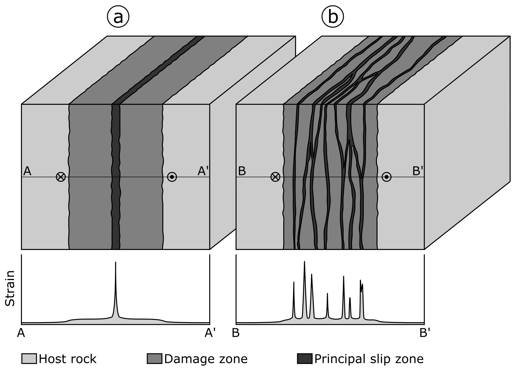
Figure 1Conceptual end-member models of fault zone architecture. (a) According to the model of Caine et al. (1996) a fault is a relatively simple structure, where most of the strain is accommodated at a single, quite narrow fault core hosting a principal slip zone. (b) Faults described by the model of Faulkner et al. (2003) are more complex and consist of a damage zone hosting multiple, anastomosing principal slip zones forming a complex network.
The Punchbowl Fault, an inactive, exhumed part of the San Andreas Fault system, typifies this conceptual model of fault zone architecture. It has a single PSZ embedded in a fault core and the surrounding damage zone. A single, continuous gouge layer with 30 cm thickness on average hosts the ∼1 mm thick PSZ. The core of the Punchbowl Fault is surrounded by an approximately 15 m thick damage zone (Chester and Logan, 1986; Chester et al., 2005).
However, other faults show a more complex structure with changing properties along strike or down dip (e.g., Wibberley et al., 2008; Faulkner et al., 2010). For example, detailed studies of the Carboneras Fault, Spain, yielded a conceptual model that is suitable for broader, typically phyllosilicate-rich fault zones, which tend to contain multiple high-strain zones (Fig. 1b; Faulkner et al., 2003). The Carboneras Fault is a predominantly strike-slip structure that comprises an ∼1 km thick tabular zone of continuous and anastomosing strands of phyllosilicate-rich fault gouge containing lenses of fractured protolith surrounded by an approximately 100 m wide damage zone. Scaly clays, which typically contain anastomosing shear planes, are examples of this distributed fault zone model on the hand specimen scale (Vannucchi et al., 2003; Laurich et al., 2017).
The fault zone architecture of New Zealand's Alpine Fault, a large, transpressional plate-bounding fault and a significant geohazard, has attracted increasing attention in the last 10 years. Considered to be appropriately described by the conceptual model of Caine et al. (1996), a single PSZ is commonly supposed to accommodate displacement along the Alpine Fault (e.g., Barth et al., 2012; Sutherland et al., 2012; Barth et al., 2013; Norris and Toy, 2014; Toy et al., 2015; Williams et al., 2016; Townend et al., 2017; Lukács et al., 2018; Schuck et al., 2018; Williams et al., 2018). Here, by combining results of these previous studies on the Alpine Fault's structure with new field observations, microstructural, mineralogical and geochemical analyses, we show that the Alpine Fault has a complex fault geometry manifested by PSZ thicknesses differing substantially between investigated outcrops. This complexity is not controlled by lithology, which is unexpected given that the Alpine Fault is hosted in a quartzofeldspathic protolith, which commonly fosters localization compared to phyllosilicate host rocks (Faulkner et al., 2003). This implies that the Alpine Fault does not fit our paradigmatic models of fault zone architecture.
2.1 The Alpine Fault and associated hazard
The Alpine Fault localizes most of the deformation associated with the relative displacement between the Australian Plate and the Pacific Plate. The fault is dominantly dextral transpressive and runs through the South Island of New Zealand. The straight, 800 km long surface trace extends from Milford Sound in the SW to Hokitika in the NE, where it transfers displacement onto the four main fault strands of the Marlborough Fault System (the Wairau, Awatere, Clarence and Hope Faults; Fig. 2a). The Alpine Fault maintains a constant NE-SW strike for its entire length, but the fault dip changes from 80–90∘ SE SW of the Dun Mountain Ophiolite Belt (DMOB) to 30–50∘ SE in the central segment (Barth et al., 2013). The shallowest 1–2 km of the fault NE of Haast display “serial partitioning”, i.e., northerly striking oblique thrust sections alternate with easterly striking dextral strike slip sections of 1–10 km length (Norris and Cooper, 1995; Barth et al., 2012).
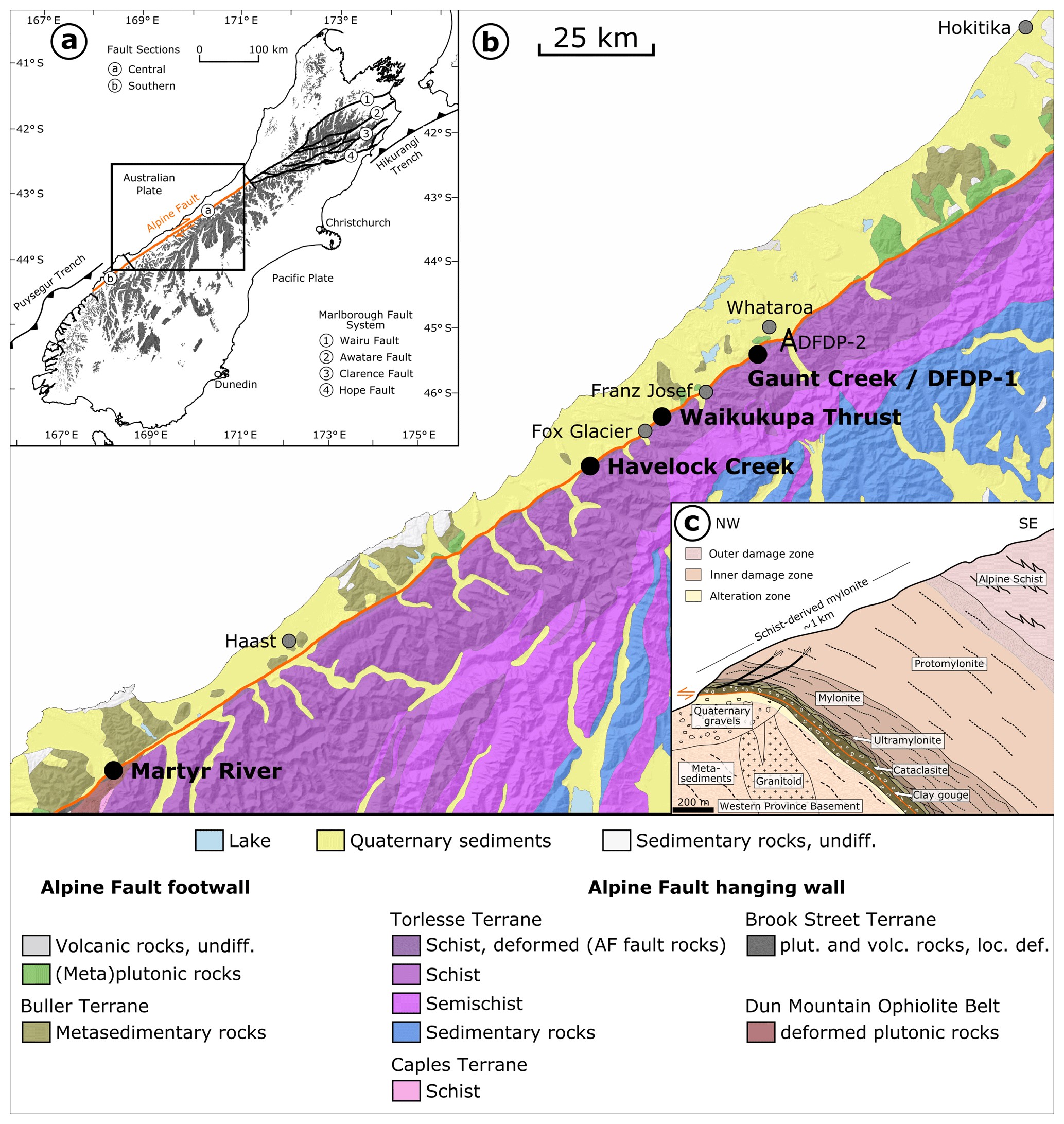
Figure 2(a) Plate tectonic setting of New Zealand's South Island with the Alpine Fault's onshore segment being highlighted in orange. Position of (b) is indicated by black box. (b) Simplified geological map of the study area. Alpine Fault trace shown in orange. Locations of investigated outcrops: Martyr River, 43∘7′47′′ S 168∘33′40′′ E; Havelock Creek, 43∘32′15′′ S 169∘52′15′′ E; Waikukupa Thrust, 43∘26′22′′ S 170∘4′8′′ E; Gaunt Creek, 43∘18′58′′ S 170∘19′20′′ E. Map is based on the geological map of New Zealand's South Island (Edbrooke et al., 2015) and the digital elevation model of Columbus et al. (2011). (c) Typical shallow-depth sequence of Alpine Fault rocks. The figure was modified from Norris and Cooper (2007). Extents of alteration zone were derived from Sutherland et al. (2012) and extents of inner and outer damage zone from Townend et al. (2017).
A 470 km right-lateral offset of the DMOB defines the minimum cumulative displacement along the fault (Sutherland et al., 2007). Displacement-normal shortening is on the order of 90±20 km (Little et al., 2005). Strike-slip displacement rates are between 21 and 29±6 mm yr−1 (Norris and Cooper, 2000) corresponding to 60 %–80 % of the total relative velocity between the bounding plates (DeMets et al., 2010). Seismic investigations indicate a maximum exhumation of ∼35 km from a deep crustal, subhorizontal, NE-dipping detachment (Stern et al., 2001; Little et al., 2005). Long-term exhumation rates of 6–9 mm yr−1 are inferred from 40Ar∕39Ar ages encountered between Franz Josef Glacier and Fox Glacier (Little et al., 2005). A combination of these high exhumation rates and meteoric fluid circulation driven by steep topographic gradients results in a very high geothermal gradient of up to 125 ∘C km−1 encountered in valleys (Menzies et al., 2016; Sutherland et al., 2017).
Currently, the Alpine Fault does not exhibit creep and is thought to be seismically locked to a depth of 12–18 km (Beavan et al., 2007). It is known to rupture in large earthquakes (Mw>8), while generating up to 8–9 m of lateral and up to 1 m of normal displacement (Sutherland et al., 2007; Nicol et al., 2016). Offset and deformed Quaternary features demonstrate that Alpine Fault earthquakes rupture the ground surface (e.g., Cooper and Norris, 1990; Berryman et al., 2012; Schuck et al., 2018). While events like the most recent one in 1717 AD might rupture the entire fault, differing recurrence intervals of 263±68 years for the central segment and 291±23 years for the southern segment demonstrate that individual sections of the fault might fail independently (Fig. 2a; Sutherland et al., 2007; Howarth et al., 2018 and references therein). Considering the potential to produce large-magnitude earthquakes and the time passed since the last event, the Alpine Fault is late in its seismic cycle and thus constitutes one of the South Island's major geohazards.
2.2 Lithology
The Australian Plate footwall assemblage encompasses Paleozoic to Cretaceous plutonic rocks intruded into metasediments (Fig. 2b). As these units are mostly overlain by Quaternary fluvioglacial sediments, footwall rocks are poorly exposed (e.g., Toy et al., 2015). In the Pacific Plate hanging wall, a narrow, 12–25 km wide elongate belt of metamorphosed sediments, the Alpine Schist, is exposed from the SW of Jackson Bay to the fault's NE termination (e.g., Sibson et al., 1979; Grapes and Watanabe, 1992; Scott et al., 2015). The Alpine Schist originates mostly from the Torlesse Terrane. This terrane is a polygenetic metamorphic suite with the Alpine Schist being its high grade and most recently formed (Late Cretaceous) part (Roser and Cooper, 1990; Scott et al., 2015).
The amphibolite–greenschist facies rocks of the Alpine Schist have dominantly metapelitic to metapsammitic compositions, with rare metabasite and metachert. Metamorphic grade decreases from K-feldspar and oligoclase amphibolite facies through garnet, biotite and chlorite greenschist facies to pumpellyite–actinolite and prehnite–pumpellyite facies with increasing SE distance from the fault plane (e.g., Grapes and Watanabe, 1992; Scott et al., 2015). However, a combination of significant right-lateral displacement and high exhumation rates resulted in 200–300 m wide inverted metamorphic sequences cropping out structurally above brittle fault rocks in the central segment (Cooper and Norris, 2011). Irrespective of local variations, typical mineral phases encountered in Alpine Schist-derived fault rocks are quartz, feldspar, garnet, muscovite, biotite, other minor phases and, in the case of metabasites, hornblende and epidote (Norris and Cooper, 2007). At the Waikukupa Thrust there are remnants of highly disrupted, intensely strained and sheared granite pegmatites indicating simple shear strains of more than 150 and coeval pure shear stretches of ∼3.5 (Norris and Cooper, 2003; Toy et al., 2013).
Whereas the Alpine Schist constitutes the protolith of fault rocks in the central portion of the Alpine Fault, a comparatively small (∼550 m thick) sliver of the Brook Street Terrane (BST) is the protolith of samples from the southern segment (Fig. 2b). The sliver is surrounded by the DMOB and bound to the NE by the Alpine Fault. The BST is the remnant of a Permian island-arc system, mainly composed of basaltic to andesitic volcaniclastic and sedimentary rocks of prehnite to pumpellyite and locally greenschist metamorphic grade (Spandler et al., 2005).
2.3 Fault rocks of the Alpine Fault
Exhumation from deep-crustal levels resulted in the formation of an approximately 1 km wide characteristic sequence of hanging wall fault rocks (e.g., Reed, 1964; Sibson et al., 1979; Cooper and Norris, 2011; Toy et al., 2015, Fig. 2c). Progressive northwestward-increasing strain of the Alpine Schist yielded protomylonites to ultramylonites that are overprinted by a cataclastic fault zone displaying increasing damage towards the PSZ (Williams et al., 2016). Cataclastic shears in the ultramylonites are filled with phyllosilicates and exhibit strike-slip, normal and reverse kinematics. Cataclasites are composed of comminuted mylonite fragments within a matrix of pulverized host rock, authigenic chlorite, muscovite and illite (Sibson et al., 1979; Norris and Cooper, 2007; Boulton et al., 2012). Intense chloritization imparted a typical pale green color to these 10–30 m wide cataclasites (Warr and Cox, 2001), which are cemented by authigenic phases, dominantly phyllosilicates and carbonates (Sutherland et al., 2012; Toy et al., 2015; Williams et al., 2016). The fault's PSZ cross-cuts all other structures, which indicates that it is the last active part of the fault system and accommodates the coseismic displacements that manifest as offset Quaternary features (e.g., Cooper and Norris, 1990; Berryman et al., 2012; Schuck et al., 2018). It is an incohesive and fine-grained gouge up to ∼50 cm in thickness (Norris and Cooper, 2007; Boulton et al., 2012). Authigenic phyllosilicates cement the PSZ converting it into an impermeable hydraulic barrier preventing cross-fault fluid flow (Sutherland et al., 2012; Menzies et al., 2016). There is no location providing a continuous section from hard rock hanging wall to hard rock footwall (Townend et al., 2009).
2.4 The Deep Fault Drilling Project
Studying the physical character of tectonic deformation at depth within a continental fault late in its interseismic period provided the motivation for the Deep Fault Drilling Project (DFDP, Fig. 3a, Townend et al., 2009). Phase 1 drilled two ∼100 m (DFDP-1A) and ∼150 m (DFDP-1B) deep pilot holes in January 2011 (Sutherland et al., 2012; Toy et al., 2015). These DFDP-1 boreholes provide a continuous section of fault rocks from hanging wall ultramylonites to footwall gravels enabling lithological (Toy et al., 2015), mineralogical (Schleicher et al., 2015), geomechanical (Boulton et al., 2014; Carpenter et al., 2014) and geophysical analysis (Sutherland et al., 2012; Townend et al., 2013). In total, three ∼20 cm thick PSZs were encountered. In DFDP-1A the PSZ is located between 90.67 and 90.87 m depth (Fig. 3a, b), and in DFDP-1B two PSZs were encountered at 128.30–128.50 and 143.96–144.16 m depth, respectively (Fig. 3a, Toy et al., 2015).

Figure 3(a) Schematic overview of Deep Fault Drilling Project (DFDP) boreholes drilled in phase 1 at Gaunt Creek and phase 2 within the Whataroa River valley. Star at DFDP-1A indicates location of (b). (b) Segment of 180∘ scan of PSZ encountered at DFDP-1A drill core (run 66, section 1). (c) Individual fault rock units of the Alpine Fault Zone are well-recognizable at the outcrop Gaunt Creek, in close proximity to the DFDP boreholes. Star indicates location of (d) and (e). (d) An approximately 1 cm thick, brown layer indicated by stippled orange lines, was interpreted to represent the PSZ at Gaunt Creek. (e) Sample location (specimen shown in Fig. 5b) some 10 s of centimeter SW of location shown in (d). Figure modified according to Sutherland et al. (2012) and Boulton et al. (2014).
Another two boreholes were drilled in DFDP phase 2 (DFDP-2A: 212.6 m MD – measured depth; DFDP-2B: 893.1 m MD) about 7.5 km ENE of the location of DFDP-1 (Fig. 2b, Toy et al., 2017). Phase 2 yielded cuttings for petrographic investigations (Toy et al., 2017) and provided various insights into fault zone architecture by wireline logs (e.g., Janku-Capova et al., 2018; Massiot et al., 2018) but was not able to penetrate and sample the fault core due to scientific and technical difficulties (Toy et al., 2017). DFDP boreholes from both phases provide the opportunities for long-term monitoring of the Alpine Fault (e.g., Sutherland et al., 2015).
2.5 Study locations
For this study, all known outcrops with accessible PSZ between Martyr River in the SW and Kokatahi River, SSE of Hokitika in the NE were investigated in the austral summer 2015/2016 (Fig. 2b). Furthermore, cataclasite and the fault gouge samples were available from the DFDP-1A core. Four of the five investigated locations, Havelock Creek, Waikukupa Thrust, Gaunt Creek and the core of DFDP-1A, are in the central segment of the Alpine Fault with the Alpine Schist as hanging wall host rock. Rocks of the BST constitute the host of fault rocks encountered at Martyr River, the fifth and southwestern-most location. All outcrops are located along river banks providing good outcrop conditions.
Waikukupa Thrust is the only studied site that is considered to be inactive. Incision of the Waikukupa River resulted in a geomechanically unfavorable geometry leading to the abandonment of this thrust segment and re-localization of deformation approximately 700 m to the NE at Hare Mare Creek (Norris and Cooper, 1997).
3.1 Sampling
Fault rocks at Martyr River and Havelock Creek were sampled using hammer and chisel. At Waikukupa Thrust and Gaunt Creek samples were recovered using a hand-held chainsaw equipped with a silicon carbide chain. After recovery, all outcrop samples were immediately wrapped in aluminum and plastic foil to slow down drying. This procedure allowed for continuous transects across the PSZ, which juxtapose hanging wall cataclasites and footwall gravels, to be sampled from Martyr River and Waikukupa Thrust. However, the samples broke apart along the PSZ during shipping. An intact contact of PSZ on footwalls material was only preserved from Gaunt Creek.
In summary, hanging wall fault rocks are available from Martyr River, Waikukupa Thrust and DFDP-1A. PSZ samples originate from all five locations and footwall rocks were taken at Martyr River, Waikukupa Thrust and Gaunt Creek.
3.2 Microstructural analysis
Samples from Martyr River, Waikukupa Thrust and Gaunt Creek were cut dry with a low-speed saw perpendicular and parallel to the fault trace. From all locations, subsamples were selected for microstructural analyses and subsequently embedded in resin prior to the preparation of 29 dry-polished thin sections using otherwise standard techniques.
Microstructural investigations were conducted using optical microscopy, scanning electron microscopy (SEM), transmission electron microscopy (TEM) and cathodoluminescence analyses (CL). Thin sections were studied with a Leica DM RX optical microscope and a FEI Quanta 3D SEM with focused ion beam (FIB; dual-beam machine). The SEM, equipped with a field emission gun, operated at 20 kV in backscatter electron mode (BSE) and allowed semi-quantitative geochemical analyses with its EDAX energy dispersive X-ray analyzer (EDX). For TEM analyses, a platinum strip was deposited on the sites selected with the FIB of the SEM to enable subsequent preparation of 14 thin foils ( µm) with a FEI FIB 200 following the procedure outlined by Wirth (2004, 2009). A FEI Tecnai G2 F20 X-Twin TEM with Gatan Tridiem energy filter, Fischione high-angle annular dark field detector (HAADF) and EDX operated at 200 kV and allowed nanoscale investigation. Cathodoluminescence analyses on calcite veins and cement were performed on thin sections using an Olympus polarizing microscope. The Lumic HC1-LM hot cathode CL microscope operated at 14 kV, 0.0001 mbar and ∼0.6 mA electron beam and 2.5 A filament current, respectively.
Microstructural analyses are mostly based on qualitative observations, but some quantitative information was obtained by image analysis using the open source software FIJI/ImageJ (Schindelin et al., 2012; Schneider et al., 2012).
3.3 Mineralogical and geochemical investigations
18 bulk rock powder samples for mineralogical and geochemical analyses were prepared with a jaw crusher and subsequently sieved to grain sizes <62 µm. A McCrone micronization mill provided the <10 µm grain size fraction for the quantitative mineralogical analysis.
3.3.1 X-ray diffraction analysis
The mineralogical compositions of the samples were determined by X-ray diffraction (XRD) analysis on random powder samples loaded from the back side of the sample holders (∅ 16 mm). XRD analyses were performed with a PANalytical Empyrean X-ray diffractometer operating with Bragg–Brentano geometry at 40 mA and 40 kV with CuKα radiation and a PIXel3D detector at a step size of 0.013∘2Θ from 4.6 to 85∘2Θ and 60 s per step.
Mineralogy was determined qualitatively with the EVA software (version 11.0.0.3) by Bruker. Rietveld refinement for quantitative mineralogy was performed using the program BGMN and the graphical user interface Profex (version 3.10.2, Döbelin and Kleeberg, 2015) calibrated for the used diffractometer. The error of quantitative analyses is expected to be in the range of 3 wt %. Goodness of fit was assessed by visually inspecting the differences between measured and modeled diffractograms and by aiming to obtain Rwp values lower than 3, a value arbitrarily chosen (Toby, 2006).
Bulk powder subsamples (45 mg), dispersed in 1.5 mL of de-ionized water and disaggregated in an ultrasonic bath, were placed on round (∅ 3.1 cm) glass slides and air-dried for subsequent smectite and chlorite analyses. Identification of smectite was performed after ethylene glycolation at 45 ∘C for at least 12 h (2.4–25∘2Θ), and heating to 500 ∘C for 1 h allowed us to differentiate between chlorite and kaolinite (2.4–25∘2Θ, Moore and Reynolds Jr., 1997).
Illite polytype analyses to differentiate between authigenic and detrital (i.e., comminuted muscovite) species were conducted on selected samples with high illite and/or muscovite concentrations (Moore and Reynolds Jr., 1997; Haines and van der Pluijm, 2008). Diffractograms for polytype analyses were acquired between 16 and 44∘2Θ at a step size of 0.013∘2Θ with 200 s per step. All diffractograms and Rwp values are provided in the Supplement.
3.3.2 X-ray fluorescence spectrometry
X-ray fluorescence spectrometry (XRF) with a PANalytical AXIOS Advanced spectrometer enabled study of geochemical variations of major elements. For this purpose, after drying of ∼1.1 g of bulk rock powder overnight at 105 ∘C, 1 g of sample material, 6 g of LiBO2 and 0.5–0.7 g of ammonium nitrate, acting as oxidizing agent, were fusion digested at increasing temperatures from 400 to 1150 ∘C with a dilution of 1:6. The loss on ignition (LOI) providing volatile contents was determined on 20–30 mg of powder samples with an Euro EA Elemental Analyzer.
To evaluate fluid-related element mobilization, XRF data were analyzed based on the equation of Gresens (1967) for composition–volume relationships resulting from metasomatic alterations, employing the isocon method (Grant, 1986, 2005). In this, the chemical composition of each investigated fault rock sample (i.e., altered rock) is plotted against the chemical composition of the host rock (i.e., unaltered rock). An isocon, a straight line through the origin, separates species enriched relative to the host rock plotting above from those depleted plotting below. It follows the equation
with CA and CH being element concentrations of the altered and the host rock, respectively, and m referring to the isocon's slope. Enrichment or depletion (ΔCi) of an element i relative to its host rock equivalent is calculated as follows:
The inverse of the isocon's slope (m−1) indicates overall mass gain () or loss (), respectively. Mass gains (%) are calculated as () × 100 %. A negative mass gain corresponds to a mass loss (%).
To derive isocon slopes, Grant (2005) suggested five approaches: (I) clustering of , (II) a best fit of data forming a linear array through the origin on an isocon diagram as graphical equivalent to (I), (III) assuming that certain elements are immobile, or assuming (IV) mass or (V) volume to be constant during alteration. However, it has previously been shown that Al and Ti – elements commonly assumed to be not affected by fluid-related alteration (e.g., Grant, 2005; Dolejš and Manning, 2010) – are mobilized by fluid-related alteration at the Alpine Fault. Furthermore, authigenic mineral formation is thought to affect both fault rock mass and rock volume (Schuck et al., 2018). As identification of clusters (I) or linear arrays (II) selects only a subset of all data points, and these selections may be biased, we used a linear best fit through all data points to determine isocon slopes.
Identification of the host rock is just as important as correctly determining the slopes of the isocons (Grant, 1986). We defined a reference protolith composition for fault rocks from Havelock Creek, Waikukupa Thrust, Gaunt Creek and DFDP-1A (Table S1 in the Supplement) based on the average of geochemical compositions of Alpine Schist data reported by Grapes et al. (1982), Roser and Cooper (1990) and Toy et al. (2017). These analyses are derived from the entire central segment of the Alpine Fault and individual data points display little variation.
At Martyr River, the geochemical compositions by Spandler et al. (2005, see their Table 1) have been averaged, and used as host rock composition (Table S1 in the Supplement). Their analyses from Bluff Complex and Takitimu Mountains were excluded, because the origin and some geochemical features, respectively, are different from the bulk BST (Spandler et al., 2005). We also note the isocon method has limitations for understanding fluid-assisted alteration related to fault activity at Martyr River. This is because the width of the Alpine Fault deformation zone at this location is larger than the thickness of the BST (Fig. 2b), so faulting-related fluid–rock interaction likely occurred with the DMOB and the geochemical composition of the reference protolith was already affected by fluid-related alteration. Furthermore, the BST is compositionally very heterogeneous due to magmatic differentiation so it is difficult to choose a single representative host rock geochemical composition. Fortunately, these variations only substantially affect the absolute quantification. The method nevertheless allows for relative geochemical changes within the fault zone at this location to be accounted for. The limitations regarding absolute quantification of concentration changes as result of hydrothermal alteration also apply to the Alpine Schist.
Table 1Summary of observed hanging wall cataclasite microstructures. PSZ: principal slip zone.

4.1 Field observations
Individual units of the Alpine Fault rock sequence – (ultra)mylonites, cataclasites and footwall gravels – can be identified clearly at all sites investigated. However, weathering and landslides complicate the unambiguous identification of the PSZ at Gaunt Creek and Havelock Creek. This is exemplified by an approximately 1 cm thick, fine-grained, brown, fractured and discontinuous layer interpreted to represent the PSZ at Gaunt Creek (Fig. 3c–e) that was identified through sampling to be a footwall feature approximately 8 cm below the PSZ (see Sect. 4.2.3). Furthermore, measurements of fault orientation are only robust in the well-exposed outcrops at Waikukupa Thrust (50∘/44∘ SE) and Martyr River (59∘/51∘ SE) and those from Gaunt Creek (61∘/32∘ SE) and Havelock Creek (102∘/55∘ SE) should be treated with caution.
Thicknesses of fault gouges constituting the PSZ vary among individual locations, including the DFDP-1A core (Figs. 3–5), and decrease in the following order: Havelock Creek (∼50 cm; Figs. 4a and 5a), Gaunt Creek (∼30–40 cm; Figs. 3c–e and 5b), DFDP-1A (20 cm; Fig. 3b), Waikukupa Thrust (∼4 cm; Figs. 4b and 5c) and Martyr River (∼1–2 cm; Figs. 4c, d and 5d). Except for Martyr River, these locations have the same protolith (Fig. 2b; see Sect. 4.3). Furthermore, there is no systematic variation of PSZ thickness in distance along strike in these outcrops.
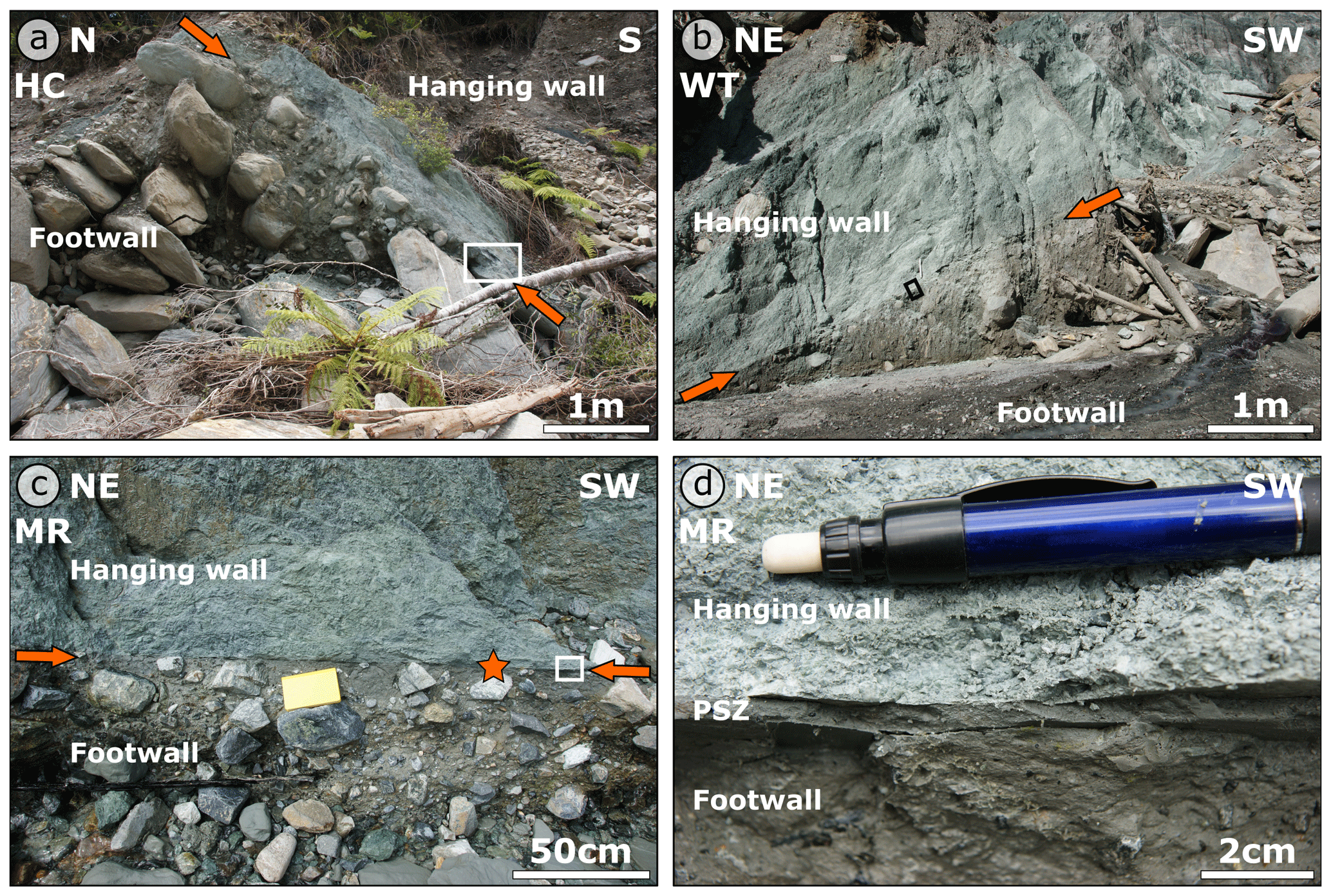
Figure 4Outcrops of Alpine Fault Zone rocks. (a) Whereas pale green hanging wall cataclasites and larger Quaternary footwall gravels are clearly identified at Havelock Creek, the contacts and hence thickness of the PSZ (indicated by arrows) to overlying and underlying units, respectively, are only poorly constrained. The white box indicates position of Fig. 5a. (b) The PSZ at Waikukupa Thrust as indicated by arrows is well-defined and straight. The black box gives location of sample presented in Fig. 5c. (c) At Martyr River, hanging wall and footwall rocks are sharply separated by a well-defined PSZ (indicated by arrows). The white box indicates position of (d). The star gives the sample location for the specimen shown in Fig. 5d. (d) The PSZ at Martyr River is between 1 and 2 cm thick. HC: Havelock Creek; WT: Waikukupa Thrust; MR: Martyr River.
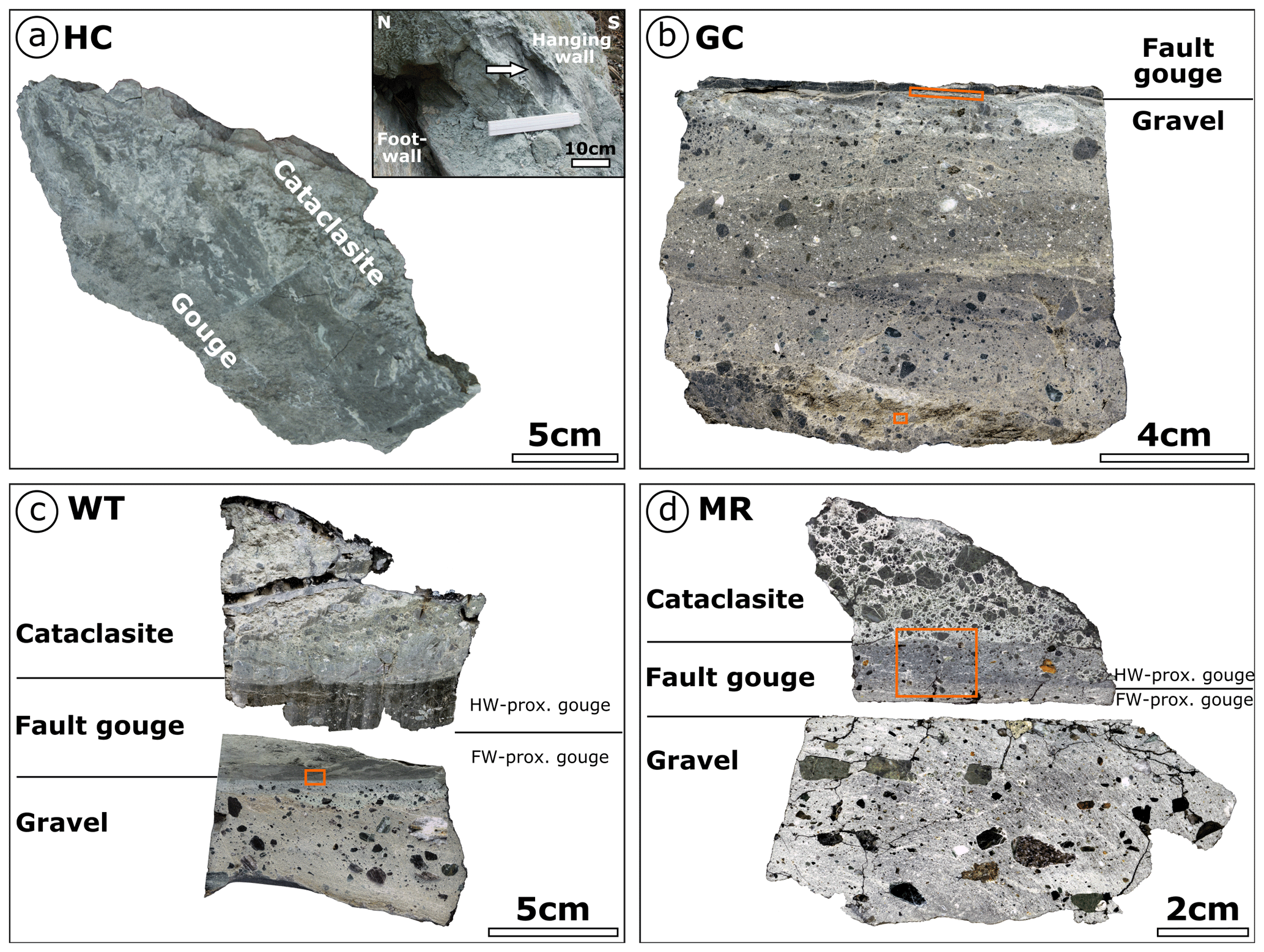
Figure 5Investigated outcrop samples. (a) The contact between hanging wall cataclasites and thick fault gouge at Havelock Creek is poorly developed and appears to be transitional over ∼8 cm. The inset provides a close-up of the sample location (indicated by the arrow). (b) Identifying the fault gouge in the field at the location Gaunt Creek turned out to be difficult. Consequently, only the lowermost part of the PSZ has been sampled. Contact between the PSZ and footwall is sharp. The orange box at the contact indicates location of Fig. 7k–m; the orange box at the bottom indicates location of Fig. 6d. (c) The thin fault gouge at Waikukupa Thrust consists of a hanging wall-proximal and footwall-proximal layer. The orange box gives location of Fig. 7j. (d) The contacts of the thin PSZ with hanging wall and footwall rocks, respectively, are sharp at Martyr River. Fault gouge consists of a hanging wall-proximal and a footwall-proximal layer. The orange box gives location of Fig. 7a and b. HC: Havelock Creek; GC: Gaunt Creek; WT: Waikukupa Thrust; MR: Martyr River.
4.2 Microstructures
The fault rocks of Alpine Fault hanging wall, PSZ and footwall contain clasts embedded in a fine-grained matrix. We define matrix as fine particles – detrital and authigenic – belonging to the clay-size fraction, i.e., <2 µm (Fig. 6a). In fact, the typical matrix grain size is ≪1 µm. The matrix is composed of abundant phyllosilicates of detrital (see Sect. 4.3) and authigenic (e.g., Fig. 6a) origin and detrital particles, mostly quartz and feldspar. The latter are subangular to rounded in shape with elongate to moderate sphericity and commonly with edges that have been affected by dissolution and mineral alteration processes (Fig. 6a).
Clasts embedded in the fault rock matrix are predominantly comminuted quartz, feldspar and mica grains, as well as fragments of Alpine Schist and mylonite. In addition, there are two more groups of clasts. The first one comprises compact, almost pore-free, fine particles with distinct boundaries but of similar composition compared to the surrounding matrix (Fig. 6b). This group of clasts is termed matrix clasts in the following. The second group comprises small areas, which are microstructurally similar to matrix clasts. These features are characterized by brighter grey values in BSE mode, and typically high porosities so they are easy to differentiate from the surrounding material (Fig. 6c). EDX analyses demonstrate that they are compositionally identical to the surrounding matrix. Because comparison of optical and scanning electron microscopy images reveals that these structures look like matrix clasts under plain polarized light (Fig. 6d and e), we refer to them as bright matrix clasts in the following.
The distinct lithological and (micro-to-macro) structural characteristics of all units are described in detail in the following sections and summarized in Tables 1 (hanging wall), (PSZ) and 3 (footwall).
4.2.1 Hanging wall cataclasites
Clasts embedded in the fine-grained cataclasite matrix at DFDP-1A and Waikukupa Thrust are mostly quartz and feldspars, with commonly fractured, dissolved and altered edges (Fig. 6a). Furthermore, matrix clasts are encountered close to the contact with the PSZ (<1.35 m at DFDP-1A and <10 cm at Waikukupa Thrust, respectively). In contrast, quartz and feldspars only constitute ∼5 % of clasts at Martyr River. There, most clasts are polymineralic aggregates consisting of quartz, feldspar, chlorite and rarely biotite and fragments of calcite veins (Fig. 6f and g). There are subordinately fragments of Alpine Schist (all locations) and mylonites (Waikukupa Thrust). At DFDP-1A and Waikukupa Thrust these fragments display ∼150 µm wide, gouge-filled microfaults (Table 1). At Waikukupa Thrust, there are also clay–clast aggregates (CCAs; Boutareaud et al., 2008). At both thin section and outcrop scale, the amount and size of clasts generally decrease towards the PSZ and both vary systematically with PSZ thickness (Table 1; see also Boulton et al., 2012; Toy et al., 2015): locations with a thinner PSZ contain more clasts in the hanging wall, which tend to be larger, compared to locations with a thicker PSZ.
Open cracks, typically several millimeters long and up to hundreds of micrometer wide, increase in abundance towards the PSZ at DFDP-1A and Waikukupa Thrust. Furthermore, microfaults (∼5–130 µm thick) cross-cut cataclasites at these locations. They contain comminuted particles and authigenic phyllosilicates and range in maturity: mature microfaults display a well-developed fine-grained fault gouge with particles up to tens of micrometers in size but mostly smaller than 2 µm (Fig. 6h). In contrast, juvenile microfaults contain poorly sorted particles up to a few hundred micrometers in size with the majority larger than 10 µm. In addition, some microfaults have cores made of coarser-grained matrix and clasts (Fig. 6h) or calcite veins (Fig. 6i) surrounded by fine-grained gouge.
Locally, there are patches almost completely devoid of clastic particles but with abundant authigenic flake- to needle-shaped chlorite crystals cementing pores and fractures at Waikukupa Thrust and DFDP-1A (Fig. 6j and k). The amount of these chlorite-dominated areas and authigenic phyllosilicates in general increases with decreasing distance to the PSZ and progressively cements the fault rocks. Furthermore, the matrix is cemented by calcite (Table 1). Whereas finely dispersed calcite is abundant at Martyr River, calcite at Waikukupa Thrust is usually present only in direct vicinity (<3 cm) to the PSZ. There, mutually cross-cutting calcite veins (∼15 µm thick) display small (<20 µm) dextral offsets (see Fig. 3f in Schuck et al., 2018). Furthermore, there are <100 µm large calcite-cemented breccias composed of angular fragments of clastic particles and matrix clasts (see Fig. 3c in Schuck et al., 2018). At DFDP-1A, calcite is encountered in lenses and veins, which frequently cross-cut clasts but rarely the matrix and generally increase in abundance towards the PSZ.
Locally, cataclasites are foliated. At DFDP-1A, clasts together with microfaults define a weak foliation (Fig. 6l) varying non-systematically across the investigated interval, locally displaying SC geometry. At Waikukupa Thrust and close to the PSZ, cataclastic lenses exhibit a very weak foliation parallel to the shear plane.
4.2.2 Principal slip zone fault gouges
The type of contact between hanging wall cataclasites and the fault gouge appears to correlate with PSZ thickness: where the PSZ is thicker, contacts are transitionally manifested by decreasing grain sizes (Table ), as exemplified at Havelock Creek with its transitional, poorly developed contact over 8 cm (Fig. 5a). In contrast, Waikukupa Thrust has a sharp contact on the outcrop and hand specimen scale (Figs. 4b and 5c), but displays a transition over 4 mm from a porous, clast-rich cataclasite matrix to a very dense PSZ matrix as revealed by microscopic inspection (see Fig. 3a in Schuck et al., 2018). Identification of the sharp but undulating contact at Martyr River is simple on the outcrop and hand specimen scale (Figs. 4c, d and 5d), but difficult on the microscale (Fig. 7a and b).
Table 2Summary of observed principal slip zone (fault gouge) microstructures. PSZ: principal slip zone; HW: hanging wall; FW: footwall.
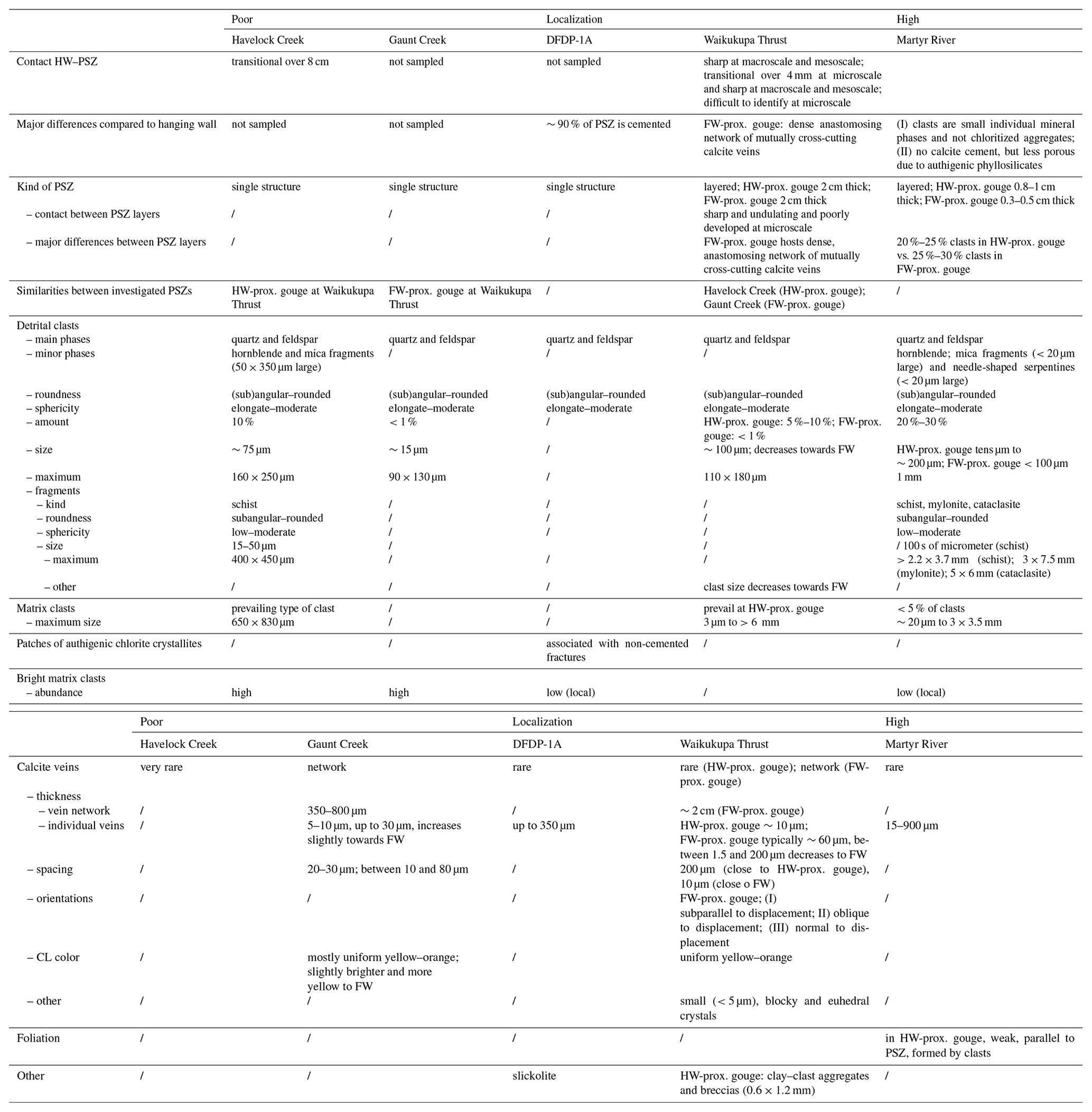

Figure 6(a) Particles forming the fault rock matrix are defined as smaller than 2 µm. Abundant authigenic phyllosilicates cement the matrix. Arrows indicate albite dissolution and alteration to phyllosilicates. (b) Matrix clasts, low-porosity, compact and clast-like areas of similar composition as the matrix, are embedded within the fault rock matrix at all outcrops. (c) Bright matrix clasts (arrows) surrounded by fine-grained matrix and some clasts. (d) Lens of matrix clasts within footwall gravels at Gaunt Creek (see Fig. 5b). The white box indicates location of (e). (e) SEM analysis shows that clasts within a lens ∼8–8.5 cm below the PSZ at Gaunt Creek are bright matrix clasts. (f, g) Corresponding PPL (f) and XPL (g) photomicrographs of hanging wall clasts at Martyr River. Identification of constituting mineral phases – mostly quartz, feldspar, chlorite – is only possible by EDX analysis. (h) Mature microfault filled by fine-grained authigenic phyllosilicates with typical grain sizes <2 µm and a core of coarser-grained material. (i) Microfault displaying a calcite vein within its core surrounded by a fine-grained matrix and some larger clasts. (j) Locally, pores and cracks are cemented by fine-grained, authigenic phyllosilicates (arrows). The orange box indicates location of (k). (k) Matrix-cementing authigenic phyllosilicates are mostly flake- to needle-shaped chlorite crystallites. (l) Foliated cataclasite (top left to bottom right) sampled 25 cm above the PSZ. WT: Waikukupa Thrust; HC: Havelock Creek; GC: Gaunt Creek; MR: Martyr River; DFDP: Deep Fault Drilling Project core 1A; STEM: scanning transmission electron microscopy; BSE: backscatter electron microscopy; PPL: plane polarized light; XPL: cross-polarized light.
Matrix clasts are the prevailing type of clast at Waikukupa Thrust and Havelock Creek (Fig. 7c and d), but constitute less than 5 % of clasts at Martyr River. Furthermore, the phyllosilicate-cemented fault gouge at Martyr River hosts individual mineral phases, which is distinctly different from its hanging wall, where large, fine-grained chloritized particles dominate (Fig. 7b). Bright matrix clasts are present at all locations, but are abundant only at Havelock Creek and Gaunt Creek, where they, in addition to clast-like shapes, occupy areas of several hundred micrometers. In general, the amount and size of clasts weakly correlate with PSZ thickness (Table ). Where the PSZ is thinner, clasts tend to be more abundant and sizes tend to be larger. Clast sizes increase in the following order: Gaunt Creek (∼75 µm), Havelock Creek (∼75 µm), Waikukupa Thrust (∼100 µm) and Martyr River (tens of micrometers to ∼200 µm).
It is not possible to determine the amount and size of clasts within the DFDP-1A core, because more than 90 % of this unit is cemented by authigenic phyllosilicates, mostly chlorite (Fig. 7e and f). Authigenic phyllosilicates tend to nucleate along crack and grain boundaries of fractured grains. Additionally, newly formed phyllosilicates replace dissolved larger particles and mimic their original shape. Non-cemented areas are restricted to fractures. Many of these fractures contain up to 350 µm wide calcite cores, locally surrounded by gouge, microstructurally similar to microfaults observed within the DFDP-1A cataclasites (see Fig. 6i). These non-cemented, fracture-related locations host patches of fine-grained, randomly oriented and needle-shaped, authigenic chlorite crystallites. The presence of these patches within the PSZ is restricted to DFDP-1A.
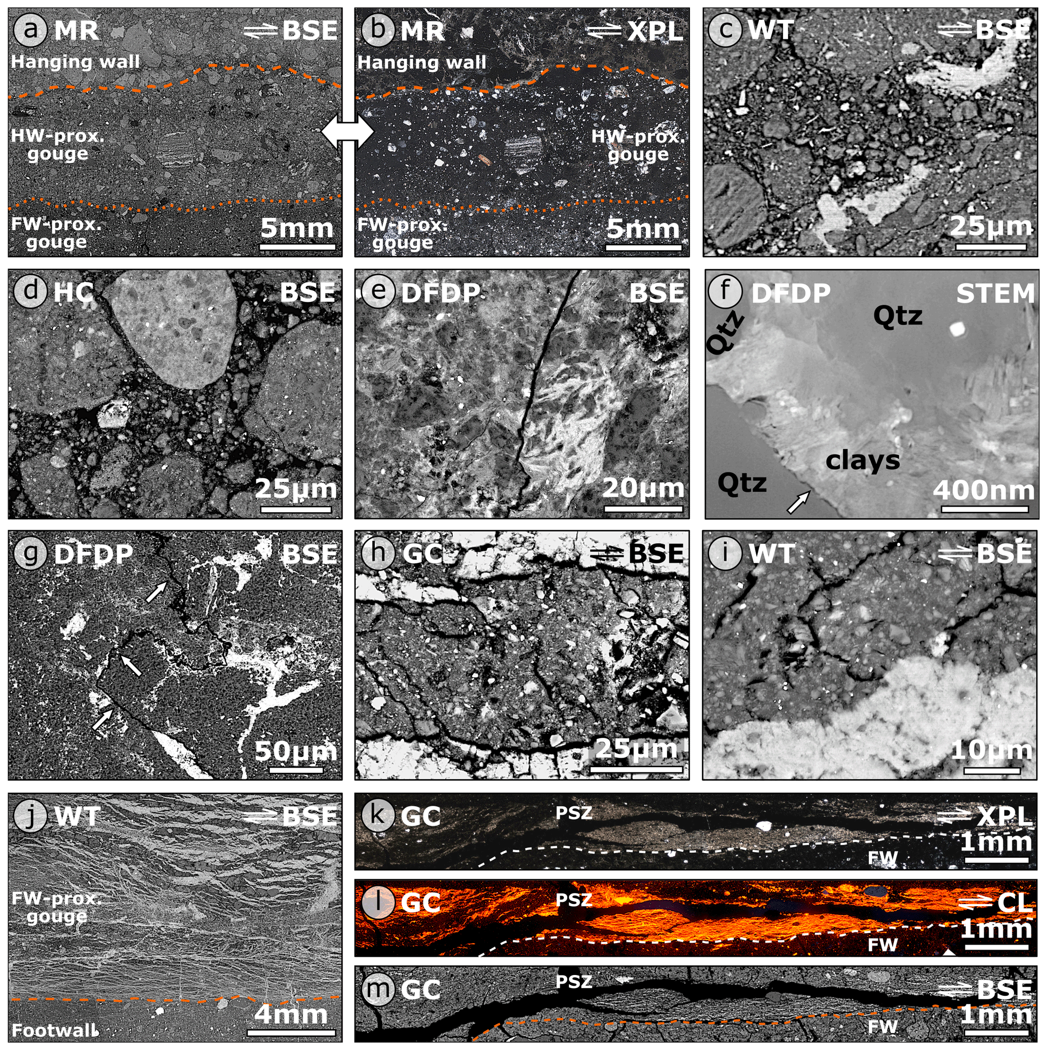
Figure 7(a) BSE and (b) XPL photomicrographs of the fault core at Martyr River. Identification of the contact between the hanging wall and PSZ (stippled line) and that between the hanging wall- and footwall-proximal gouge (dotted line), respectively, is difficult. (c, d) The hanging wall-proximal gouge at Waikukupa Thrust (c) with its large amount of matrix clasts is microstructurally similar to the PSZ at Havelock Creek (d). (e) Photomicrograph of typical microstructures of cemented PSZ at DFDP-1A core. (f) Cemented PSZ matrix of the DFDP-1A core. Pores between comminuted and dissolved (arrow) quartz grains are cemented by authigenic phyllosilicates, mostly chlorite. (g) Slickolite (white arrows) indicative of pressure solution. (h, i) Fault gouge at Gaunt Creek (h) is microstructurally similar to footwall-proximal gouge at Waikukupa Thrust (i). (j) Network of anastomosing calcite veins within footwall-proximal gouge layer at Waikukupa Thrust. The contact between fault gouge and footwall (orange line) is sharp. (k, l, m) The basal part of the PSZ at Gaunt Creek hosts a network of calcite veins terminating at the sharp contact (white/orange stippled line) with the footwall (FW). MR: Martyr River; WT: Waikukupa Thrust; HC: Havelock Creek; DFDP: Deep Fault Drilling Project core 1A; GC: Gaunt Creek; BSE: backscatter electron microscopy; XPL: cross-polarized light; STEM: scanning transmission electron microscopy; CL: cathodoluminescence.
We only saw evidence of pressure solution at one location, DFDP-1A, where there is a slickolite (Fig. 7g), a stylolite with teeth oblique to the stylolite surface (see Passchier and Trouw, 2005). However, enrichment of insoluble material or secondary phases along teeth-crowns is not observed.
PSZs at Waikukupa Thrust and Martyr River are layered and display a hanging wall-proximal and a footwall-proximal layer, respectively (Fig. 5c and d). At Martyr River, the contact is best recognized on the hand specimen scale (Figs. 4d, 5d, 7a and b), where the fault gouge is blueish-grey proximal to the hanging wall and greenish-grey proximal to the footwall. Minor differences between both gouge layers are manifested by slightly more and larger clasts in the ∼0.8–1 cm thick hanging wall-proximal layer than the ∼0.3–0.5 cm thick footwall-proximal layer (20 %–25 % vs. 25 %–30 %; Table ).
At Waikukupa Thrust, a sharp but undulating contact separates a brown-dark grey hanging wall-proximal layer with 5 %–10 % clasts from a medium-light grey footwall-proximal layer, which is clast-poor (<1 % clasts; usually <5 µm large).
The dense, clast-poor (<1 % clasts) fault gouge at Gaunt Creek is microstructurally identical to the footwall-proximal layer at Waikukupa Thrust (Fig. 7h and i). Furthermore, both gouges exhibit calcite vein networks close to the contact with the footwall (Fig. 7j–m). At Waikukupa Thrust, veins display mutual cross-cutting relationships with dextral offsets. For a detailed description of these calcite veins, the reader is referred to the preceding work of Schuck et al. (2018). At Gaunt Creek, the 350–800 µm wide vein network (Fig. 7k–m) has been subsequently affected by intensive fracturing and calcite dissolution, which hampers the identification of cross-cutting relationships. Furthermore, the contact between calcite veins and the surrounding gouge is poorly developed. Veins are typically 5–10 µm wide and tend to be thicker, less dissolved and deformed close to the footwall. CL colors are yellow–orange but slightly brighter and more yellow towards the footwall (Fig. 7l).
Apart from these vein networks, calcite veins cross-cut matrix clasts at Martyr River and the hanging wall-proximal gouge layer of Waikukupa Thrust, but are very rare at Havelock Creek. Additional hanging wall-proximal microstructures are clasts forming a weak foliation parallel to displacement at Martyr River and CCAs at Waikukupa Thrust. Furthermore, hanging wall-proximal microstructures at Waikukupa Thrust are similar to those of Havelock Creek (Fig. 7c and d), except that clasts are not homogeneously distributed but cluster randomly at Havelock Creek. Apart from the hanging wall-proximal fault gouge layer of Waikukupa Thrust, where typical clast size decreases while the size of matrix clasts increases towards the footwall, trends regarding microstructures are not observed. Most remarkably, discrete slip planes are not observed within the fault gouges.
4.2.3 Footwall gravels
Where sufficiently exposed, the contact between clast-poor PSZ and clast-bearing footwall is sharp (Figs. 4b–d; 5b, c; 7j–m). Footwall gravels are compositionally similar to overlying hanging wall cataclasites and fault gouges (Table 3). Furthermore, the same correlations regarding amount and size of clasts observed in hanging wall cataclasites and fault gouges are seen within footwall gravels (Table 3): locations with thin PSZ tend to contain more and larger clasts than locations with thicker PSZ. In addition, grain size increases with increasing distance from the PSZ. Whereas there are some bright matrix clasts at Martyr River and Gaunt Creek, matrix clasts are only encountered at Gaunt Creek. At Martyr River, footwall clasts are slightly imbricated and form a weak foliation parallel to displacement.
Table 3Summary of observed footwall (Quaternary gravel) microstructures. PSZ: principal slip zone; FW: footwall.
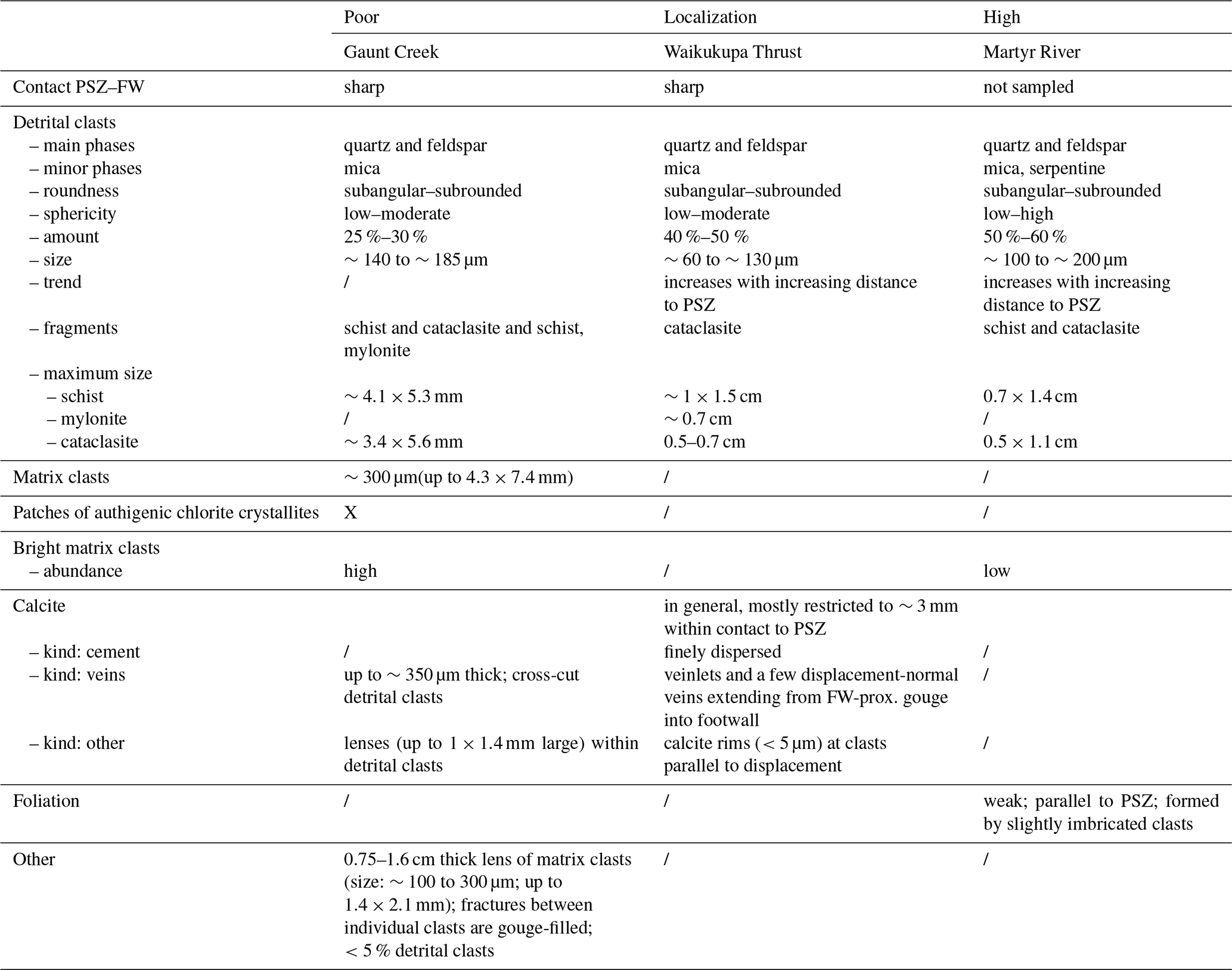
Calcite is absent at Martyr River and restricted to a ∼3 mm thick layer immediately adjacent to the PSZ at Waikukupa Thrust. There, calcite constitutes finely dispersed cement, veinlets and <5 µm thick rims at grain edges parallel to displacement. In contrast, at Gaunt Creek, calcite is predominantly found in veins and lenses cross-cutting the matrix and detrital clasts.
The ∼1 cm thick, fine-grained, brown layer erroneously interpreted as PSZ at Gaunt Creek (Fig. 3d and e), is mainly composed of fractured, subangular to subrounded matrix clasts (Fig. 6d). The amount of quartzofeldspathic clasts within this lens is <5 %. Fractures between the individual clasts are filled with a fine-grained matrix. SEM analysis reveals that these clasts are actually bright matrix clasts (Fig. 6e).
4.3 Mineralogy
There are only minor variations in the qualitative fault rock composition (Table 4). Quartz, feldspar, calcite and phyllosilicates (chlorite, kaolinite, muscovite, illite and biotite) and traces of apatite, pyrite and rutile are always present. Additionally, Waikukupa Thrust and Havelock Creek contain amphiboles, mainly hornblende, and there is epidote at Waikukupa Thrust and Martyr River. Serpentine minerals are only encountered within the fault gouge at Martyr River. Analyzed fault rocks do not contain smectite, and kaolinite is present only in traces. Furthermore, polytype analysis demonstrates that illite identified by Rietveld refinement predominantly constitutes detrital but comminuted muscovite (see Supplement).
Table 4Mineralogical composition [wt %] of investigated samples as determined by XRD analysis and subsequent Rietveld refinement. Mineral abbreviations are: Qtz: quartz; Plg: plagioclase; KFsp: potassium feldspar; Cc: calcite; Ank: ankerite; Chl: chlorite; Kln: kaolinite; Ms: muscovite; Ill: illite; Bt: biotite; Amp: amphibole; Ep: epidote; Srp: serpentine group minerals; Ap: apatite; Py: pyrite.

a Datum to calculate the distance to the PSZ refers to the center of the PSZ at Martyr River, Havelock Creek and the DFDP-1A borehole and to the contact between the PSZ and footwall at Waikukupa Thrust and Gaunt Creek. b Albite is the main plagioclase phase. c Amphibole minerals encountered are typically hornblende. d The main serpentine group minerals are equal amounts lizardite and amesite.
4.3.1 Hanging wall cataclasites
Quartz and feldspars are the dominant mineral phases in hanging wall cataclasites. They do not exhibit any clear trend towards the PSZ (Table 4). Phyllosilicates appear to decrease in content towards the PSZ. This probably is an artifact of Rietveld refinement based on the <10 µm instead of the clay-size fraction. In the DFDP-1A drill core material, the concentrations of detrital muscovite/illite decrease towards the PSZ compared to authigenic chlorite/kaolinite, which show an opposite trend. Furthermore, calcite also increases towards the PSZ at DFDP-1A.
4.3.2 Principal slip zone fault gouges
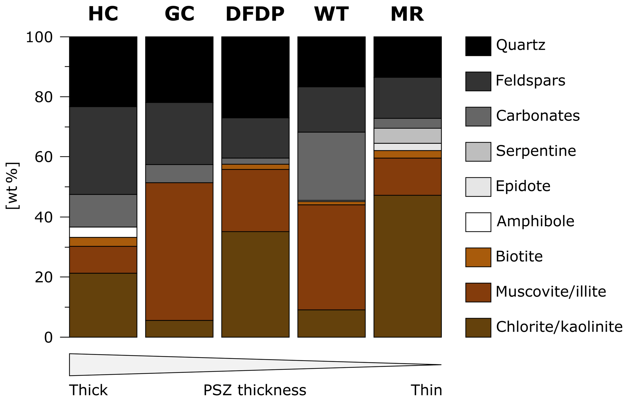
Quartz and feldspar contents vary by more than 50 % among individual locations (21 wt % at Waikukupa Thrust vs. 52 wt % at Havelock Creek; Fig. 8; Table 4). In general, these clastic phases tend to be less abundant in thinner than in thicker PSZs (Fig. 8). Phyllosilicate concentrations exhibit the opposite pattern: thinner PSZs tend to be more phyllosilicate-rich than thicker PSZs. Furthermore, chlorite/kaolinite and muscovite/illite show inverse correlations but do not vary systematically with respect to PSZ thickness. Calcite concentrations of Waikukupa Thrust (29 %) and Gaunt Creek (6 %) reflect mineralization manifested in vein networks. As calcite veins are rare at Havelock Creek, the relatively high (11 %) concentrations potentially reflect calcite cementation. In contrast, calcite concentrations within PSZs of DFDP-1A and Martyr River are lower compared to the hanging wall.
4.3.3 Footwall gravels
At Gaunt Creek, quartz and feldspar concentrations increase with increasing distance from the PSZ, while those of phyllosilicates decrease, and calcite concentrations remain constant (Table 4). Conversely, at Waikukupa Thrust, footwall concentrations of clastic phases and calcite are comparable to those of the hanging wall close to the contact with the PSZ, and phyllosilicates are slightly more abundant in the footwall compared to the hanging wall adjacent to the PSZ. Compared to the PSZ, clastic phases are significantly more abundant and amounts of phyllosilicate are lower.
4.4 Geochemistry
Element concentrations commonly scatter and, if at all, increase or decrease only slightly towards the PSZs (Table 5). The isocon analysis reveals a slight but recognizable correlation between the amount of fluid-related alteration and PSZ thickness: using the slope of the isocon as a proxy to assess the overall degree of fluid-related alteration, with a larger deviation from one indicating a higher amount of alteration, the hanging walls and footwalls of locations characterized by a thinner PSZ are generally less affected by metasomatism (Fig. 9; Tables 6 and S1). The PSZs display the same trend, but less pronounced. This is especially valid for the PSZ at Waikukupa Thrust, which is affected by a fluid-related mass change of up to 68 % (Table 6). However, microstructural observations (see Sect. 4.2.2 and Schuck et al., 2018) suggest this is most likely related to the extraordinarily large amount of calcite veins.
Table 5Geochemical composition [wt %] of investigated samples as determined by XRF.
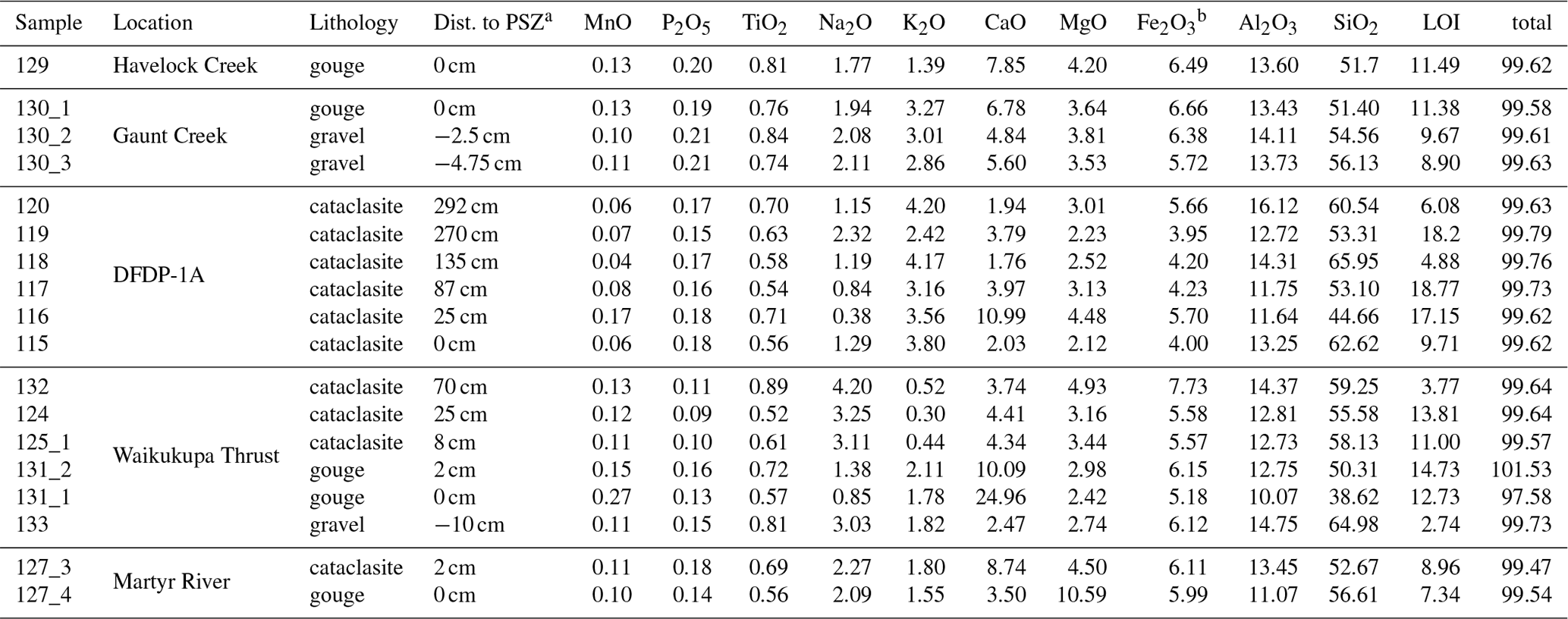
a Datum to calculate the distance to the PSZ refers to the center of the PSZ at Martyr River, Havelock Creek and the DFDP-1A borehole and to the contact between the PSZ and footwall at Waikukupa Thrust and Gaunt Creek. b Fe2O3 is total Fe content.
Enrichment of individual elements confirms this correlation: enrichment of Al2O3, CaO, LOI, MnO, P2O5 and TiO2 in hanging wall and footwall rocks is more pronounced at locations with thicker PSZ compared to those with thinner PSZ (Tables 6, S2). Element enrichment of PSZ fault gouges exhibits a similar but less pronounced trend. Comparable to the general pattern of isocon slopes described above, the PSZ at Waikukupa Thrust represents an outlier, because the large volume of calcite veins results in extraordinarily enriched CaO.
Looking at cross-fault transects, PSZs are more affected by metasomatism than hanging walls and footwalls. Furthermore, footwalls are generally less affected by metasomatism than hanging walls. However, DFDP-1A constitutes an exception, because the PSZ is less affected by metasomatism than the hanging wall cataclasites: the degree of fluid-related alteration increases towards the PSZ and displays the highest hanging wall amounts immediately adjacent to it (Table 6). This contrasts with Waikukupa Thrust, where samples display a continuing trend to higher amounts of fluid-related alteration from the hanging wall to the base of the PSZ close to the footwall.
Table 6Slope m of the isocon and derived mass change (%), enrichment (positive values) and depletion (negative values) of elements for samples investigated relative to the host rocks. Geochemical composition of fault rocks is taken from Table 5 and composition of host rocks from Table S1. All concentrations are in wt %.

a Datum to calculate the distance to the PSZ refers
to the center of the PSZ at Martyr River, Havelock Creek and the DFDP-1A
borehole and to the contact between the PSZ and footwall at Waikukupa Thrust
and Gaunt Creek.
b Fe2O3 is total Fe content.
5.1 Fluid-related alteration and fluid transport within Alpine Fault rocks
Isocon analyses clearly demonstrate that all investigated fault rocks have been substantially altered by fluids (Fig. 9; Table 6), which is also shown by the presence of authigenic phyllosilicates (Fig. 6a and k) and calcite vein networks (Fig. 7j–m). In general, metasomatic alteration of the fault rocks resulted in element enrichment and mass gain, which is in agreement with previous work (Schuck et al., 2018). Analyses of Martyr River fault rocks seem to show an opposite pattern but this may be an artifact related to inappropriate choice of the protolith's geochemical composition (see Sect. 3.3.1).
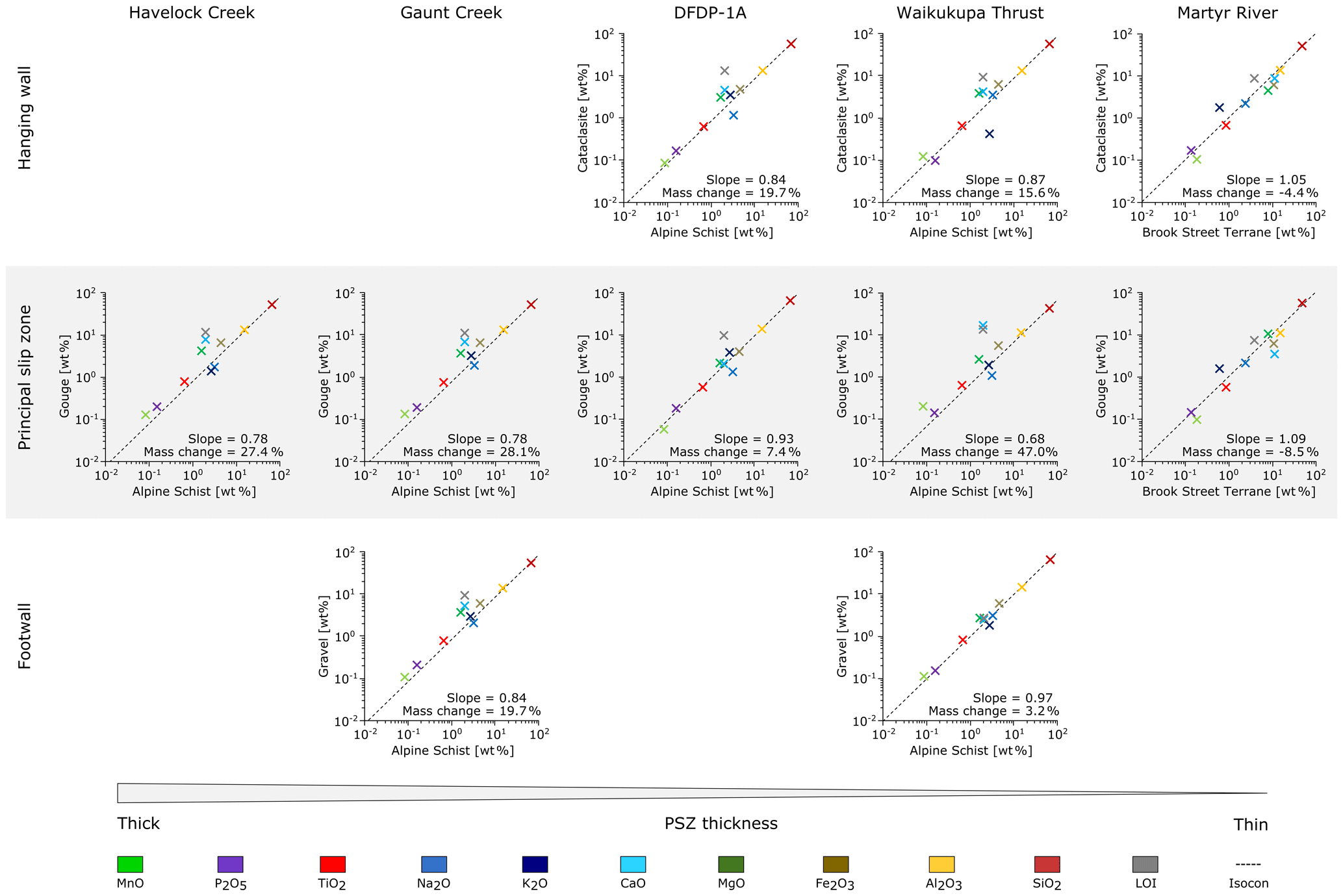
Figure 9Isocon analysis of locations investigated. In the case of multiple measurements per structural unit (hanging wall, PSZ, footwall), data were averaged to derive single values. Values are given in Table S1.
It is recognized that the Alpine Fault's PSZ constitutes an impermeable barrier restricting fluid circulation to its hanging wall (Sutherland et al., 2012; Menzies et al., 2016). Consequently, fluid-related element mobilization can be expected in the hanging wall. This is confirmed by isocon analyses: DFDP-1A samples show increasing amounts of fluid-related alteration towards the PSZ with peak values immediately above it. However, at all other locations the fault gouges are more affected by fluid-related alteration than either hanging wall or footwall rocks (Fig. 9). This suggests, in combination with networks of anastomosing calcite veins (Fig. 7j–m; Schuck et al., 2018), that there is repeated transient fluid flow within the PSZ, most likely along-fault, because the veins are parallel to the shear plane.
Overall, results of isocon analyses confirm outcomes of previous studies, which demonstrated that fluid-related alteration significantly changed the petrophysical, mineralogical, geochemical and geomechanical properties of the Alpine Fault Zone (e.g., Boulton et al., 2012; Townend et al., 2013; Carpenter et al., 2014). This supports the proposal of Sutherland et al. (2012) that an “alteration zone” within ∼50 m of the PSZ should be included as a fundamental and additional part of the Alpine Fault Zone architectural model (Fig. 2c).
Except for the slickolite observed in the DFDP-1A fault core (Fig. 7g), unambiguous microstructural evidence for pressure solution such as dissolution seams or indented and embayed clasts was not found. Annual rainfall along the NW edge of the Southern Alps is very high (e.g., Norris and Cooper, 1997, and references therein), and we suggest the observed dissolution of grain edges is related to weathering rather than deformation processes.
In summary, both the microstructures and the predominant enrichment of elements show that fluids are not responsible for stress-driven dissolution processes or for substantial mass transfer out of the fault zone. However, given that the amount of phyllosilicates and the degree of fluid-related alteration are negatively correlated (Figs. 8 and 9), the results of this study do not identify alteration mechanisms that completely explain the observed element mobilization within the fault rocks, except at Waikukupa Thrust and Gaunt Creek, where Ca enrichment is associated with the formation of calcite networks (Fig. 7j–m).
5.2 Influence of shallow-depth conditions on fault gouge structure
In the following, we consider to what extent the fault gouges formed at shallow depths, thus do not provide information about deeper fault zone architecture.
Fault gouges at Waikukupa Thrust and Martyr River are layered. Continuous transects across the fault core would sample contacts of fault gouge with both hanging wall and footwall rocks. Furthermore, they would allow for microstructures to be described across the entire PSZ. However, these continuous transects are only available from Waikukupa Thrust and Martyr River. Consequently, the absence of layered fault gouges at other locations seems to be more appropriately explained by a sampling bias than by fault gouge layers being site-specific features.
Cowan et al. (2003) analyzed low-angle detachment faults in Death Valley. There, layered fault gouges, consisting of a hanging wall- and a footwall-proximal layer, separate footwall cataclasites from weakly consolidated hanging wall sediments. Cowan et al. (2003) compare the footwall-proximal gouge layer to the hanging wall-proximal layer (i.e., the layer juxtaposed to the weakly consolidated sediments), finding the former to be fine-grained, clast-poor and supposed to have accommodated most of the strain. They interpret the formation of these layered fault gouges to reflect changing p–T conditions during exhumation, which in combination with fluid-related alteration, formed authigenic phyllosilicates within the PSZs before fault rocks were brought in contact with weakly consolidated hanging wall sediments. This juxtaposition resulted in mechanical layering, enabling the hanging wall-proximal layer to accommodate most of the strain.
By considering the different fault kinematics of the Alpine Fault compared to these faults in Death Valley (thrust vs. low-angle detachment fault), the Alpine Fault with its layered gouges described in this and previous work (e.g., Boulton et al., 2012; Schuck et al., 2018) is structurally identical to the faults analyzed in Death Valley (Fig. 10; for details see Biegel and Sammis, 2004). Furthermore, studied fault gouges bound footwall gravels, which are poorly consolidated and thus assumed to be mechanically weak. In addition, fault gouge layers juxtaposed on these weakly consolidated rocks (footwall-proximal layer at the Alpine Fault; hanging wall-proximal layer in Death Valley) are microstructurally comparable, as they contain fewer and preferentially smaller clasts than the other layers of the fault gouges (see also Table ). Furthermore, microstructures of the calcite network in the footwall-proximal layer at Waikukupa Thrust suggest localized and cyclic faulting (Schuck et al., 2018) supporting the interpretation that this gouge unit accommodated most of the strain. Consequently, layered fault gouges and associated microstructures demonstrate that strain localization and associated structural complexities within the Alpine Fault core are, at least partially, affected by shallow, hence late, processes, considering that exhumation of investigated rocks to subaerial level is accommodated entirely by the Alpine Fault's PSZ (e.g., Little et al., 2005; Toy et al., 2015).
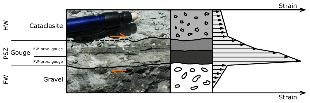
Figure 10Conceptual model providing a potential explanation of how layered principal slip zones observed at Martyr River and Waikukupa Thrust could have been formed. Resulting from the juxtaposition of weakly consolidated sediments in the footwall and relatively competent fault rocks, strain localized non-homogenously in the PSZ. The photograph example is from Waikukupa Thrust. The stippled line indicates where the contact between cataclasite and gouge is obscured by debris. The figure was modified from Cowan et al. (2003).
This interpretation has major consequences for structural investigations of the Alpine Fault's PSZ, because it implies that formation of microstructures observed in outcrops was influenced by boundary conditions not representative of those along most of the fault rocks' exhumation path. This highlights the importance of continuing to attempt to obtain samples for microstructural investigations of Alpine Fault rocks from locations and/or depths where hanging wall and PSZ fault rocks are not juxtaposed on weakly consolidated footwall sediments. Acknowledging that there is no outcrop where the hard rock hanging wall is in contact with hard rock footwall (Townend et al., 2009), drilling projects aiming to penetrate the Alpine Fault at depths where Quaternary gravels do not constitute the footwall appear to be the only promising approach to achieve this end. This would also overcome the problem of data sparsity due to the limited amount of outcrops, improving the robustness of the results.
5.3 Architecture of Alpine Fault Zone
5.3.1 Alpine Fault damage zone
Norris and Cooper (2007) suggested an average brittle damage zone width of ∼100 m, which is based on a compilation of outcrop studies in the fault's central segment. More recent investigations indicate wider damage zones: Alpine Fault outcrops in the segment south of Haast have damage zone widths between 90 and 240 m (Barth et al., 2013). Analyses of downhole geophysical data and recovered cores from the DFDP-2 borehole indicate that the Alpine Fault's hydrologically active damage zone contains an “inner zone” affected by earthquake rupture processes that is 0.5 km wide at up to 8 km depth and about 1 km wide at the surface (Fig. 2c). This inner damage zone is surrounded by an “outer zone” up to a few kilometers wide, which might only be a near-surface, topographically controlled feature (Townend et al., 2017; Massiot et al., 2018; Williams et al., 2018).
Outcrop and drill-core investigations demonstrate quite constant fracture densities within at least 500 m of the PSZ in the hanging wall and 30 m in the footwall (Williams et al., 2016, 2018), which is different from decreasing fracture densities towards the fault cores observed elsewhere (e.g., Chester et al., 2005; Faulkner et al., 2006; Mitchel and Faulkner, 2009). In fact, DFDP investigations show that apparent fracture density decreases with depth, i.e., towards the PSZ (Townend et al., 2013; Williams et al., 2016). However, this is considered as an artifact resulting from rapid exhumation and associated unloading (Williams et al., 2016). Furthermore, despite its presence across the entire damage zone, gouge-filled fractures within <160 m of the PSZ tend to be thinner (<1 cm) and more abundant (Williams et al., 2018).
5.3.2 Alpine Fault core
Extent of fault core
As a result of the pervasive alteration zone surrounding the PSZ, the fault core of the Alpine Fault is rather diffuse (Sutherland et al., 2012; Townend et al., 2013; Williams et al., 2018). Commonly, the fault gouge forming the PSZ and part of the surrounding cataclasites are considered to constitute the fault core (e.g., Williams et al., 2017). However, there is some ambiguity when it comes to actually defining the width of the fault core: Toy et al. (2015) consider a 20–30 m wide zone around the PSZ as fault core, and Sutherland et al. (2012) and Townend et al. (2017) narrow it down to 2 m surrounding the PSZ with an additional degree of localization manifested in the <0.5 m wide PSZ (Sutherland et al., 2012; Williams et al., 2016). However, by defining the damage zone as having elevated fracture densities compared to the host rock (Chester et al., 1993; Faulkner et al., 2010), and noting that there is no observable variation in fracture density within 30 m of the PSZ (Williams et al., 2016), it seems reasonable to exclusively consider the fault gouge forming the PSZ as core of the Alpine Fault's central segment. This view is supported by fault gouge microstructures: microfaults (Fig. 6h and i), predominantly encountered in hanging wall cataclasites but also present in fault gouges (Table 3), show that strain is localized to discrete structures within the PSZ. Furthermore, the fault breccias encountered in these microfaults exhibit a broad range in degree of sorting (poorly to very well) and grain size (<2–100 s of micrometer), which demonstrates that they accommodated different amounts of strain. However, microfaults appear to be a local phenomenon and there are no continuous, discrete slip planes within the PSZ, despite the large finite displacement accommodated.
This interpretation is further backed by distinct geophysical (e.g., Townend et al., 2013), petrophysical (e.g., Carpenter et al., 2014), mineralogical (e.g., Schleicher et al., 2015), microstructural (e.g., Toy et al., 2015) and geochemical (Schuck et al., 2018) properties of the PSZ. To the SW of the study area, the fault core might be more complex, because of its different lithological composition and fault orientation (Barth et al., 2013).
Implications of fault core along-strike variations for fault zone architecture
Investigated fault rocks are mostly comparable in terms of microstructures and mineralogy (Tables 1–4). However, individual outcrops display distinct differences, which will be discussed in the context of the Alpine Fault Zone's architecture in the following.
The most remarkable difference among individual locations is the variation in PSZ thickness by a factor of 25 (2 cm at Martyr River vs. 50 cm at Havelock Creek; Figs. 3–5). Similar along-strike variations of PSZ thickness have been reported previously from other faults (e.g., Sagy and Brodsky, 2009; Kirkpatrick et al., 2018). It has been suggested that such variations may be a result of the active mechanisms of deformation (Hobbs et al., 1990; Schrank et al., 2008; Sagy and Brodsky, 2009), or initial presence of heterogeneities subsequently amplified during continuous deformation (Segall and Pollard, 1983; Schrank et al., 2008; Norris and Toy, 2014; Fossen and Cavalcante, 2017). Common examples are variations in mechanical strength reflecting differing viscosities as result of compositional heterogeneities (Chester et al., 1993; Faulkner et al., 2003; Schrank et al., 2008; Rybacki et al., 2014; Nardini et al., 2018), varying geometric properties (Cowan et al., 2003; Schrank et al., 2008) or a combination of these factors (Schrank et al., 2008; Boese et al., 2012; Czaplinska et al., 2015).
As will be elaborated in the following, these explanations do not appear to be responsible for the observed variations. PSZ thickness does not vary systematically along-strike in the sampled locations (Fig. 2b). Furthermore, all locations, except Martyr River, are in the central segment of the Alpine Fault where the Torlesse Terrane Alpine Schist is the protolith. This demonstrates that variations of protolith mineralogy have no significant influence on the observed differences in PSZ thickness. However, fault gouge thickness correlates with mineralogy: thicker gouges at Havelock Creek, Gaunt Creek and the DFDP-1A core are richer in clastic phases and poorer in phyllosilicates than the thin gouges of Martyr River and Waikukupa Thrust (Fig. 8). This is astonishing, because elsewhere phyllosilicate-rich fault gouges generally tend to be wider (Faulkner et al., 2003) owing to the frictionally weak nature of these phases (Moore et al., 1997; Moore and Lockner, 2007; Lockner et al., 2011; Carpenter et al., 2015). Conversely, other fault zones with quartzofeldspathic compositions like the Alpine Fault have been found to be fairly narrow (Chester et al., 1993; Faulkner et al., 2003). Consequently, unlike these fault zones, the Alpine Fault displays a negative correlation between phyllosilicate content and fault core thickness. This suggests that strain localization within the fault core might be governed by processes insensitive to rheological variations caused by differing fault rock composition, although observed slight microstructural differences such as grain size (see also Tables 1–3) could influence localization. However, data are too scarce to derive robust conclusions. In addition, orientation of the fault (Fig. 2a and b), magnitude of stress and the stress field itself (Boese et al., 2012; Warren-Smith et al., 2017) are fairly constant along the central segment of the Alpine Fault, thus it is less likely that these parameters are responsible for the observed variations of fault gouge thickness. However, it is still possible that the extreme variations in topography typical of the Alpine Fault hanging wall generated quite different stress fields at our investigated sites (see Upton et al., 2017). Biegel and Sammis (2004) suggested that along-strike variations of gouge thickness record rupture arrest. However, our observations (and the nature of Alpine Fault outcrops in general) do not easily lend themselves to a systematic analysis of this kind in the Alpine Fault Zone.
Another approach to explain observed thickness variations is to examine the relation between fault core width and displacement. Wear models based on empirical observations describe a positive correlation between gouge thickness and displacement (e.g., Hull, 1988; Scholz, 1987). However, quantitative models of fault core evolution have so far failed to reproduce data sets compiled on natural faults (e.g., Blenkinsop, 1989; Evans, 1990; Sibson, 2003). Nevertheless, faults that accommodated larger displacements do appear to generally have thicker fault cores (Evans, 1990; Ben-Zion and Sammis, 2003; Sagy and Brodsky, 2009; Faulkner et al., 2010, and references therein). In other words: the more earthquakes a fault has seen, the thicker its PSZ may be (Ma et al., 2006; Li et al., 2013). Four of the five fault gouges investigated are located in the Alpine Fault's central segment, which is believed to rupture entirely during an earthquake (Sutherland et al., 2007; Howarth et al., 2018) and to have done so for at least the last ∼8000 years (Berryman et al., 2012). If we employ the simple relationship that shear strain in a fault zone is equal to zone width multiplied by boundary displacement, and assume constant strain distribution within the PSZ gouges, the PSZ thickness variations we describe suggest the studied fault gouges accommodated different amounts of coseismic displacement.
Other examples where PSZ thickness varies by 1 order of magnitude within tens of meters along strike are not comparable to the Alpine Fault, because these faults accommodated substantially less displacement than the Alpine Fault: Shervais and Kirkpatrick (2016) and Kirkpatrick et al. (2018) investigate a fault which accommodated displacement of the order of 10–30 km. The fault core contains at least 13 individual slip layers, suggesting that slip accommodated by these individual slip layers is most likely substantially smaller than the overall fault displacement. Consequently, observed PSZ thickness variations potentially reflect fault roughness, which is supposed to smooth as displacement increases (Sagy and Brodsky, 2009; Brodsky et al., 2011). In contrast, the Alpine Fault not only accommodated at least 470 km of displacement (Sutherland et al., 2007), its fault gouge also does not display discrete slip planes (see Sect. 4.2.2). Furthermore, contacts between the fault gouge and the hanging wall and between the fault gouge and the footwall are – where sufficiently exposed – smooth (Figs. 4b–d and 5b–d).
Consequently, Alpine Fault PSZ thickness variations reflecting different amounts of displacement imply that the studied PSZs are not part of the same shear plane, and that the Alpine Fault Zone hosts multiple fault strands, which may not be active simultaneously (Figs. 1b and 11). Figure 11 demonstrates how difficult it will be to identify the fault strand active during the most recent event.
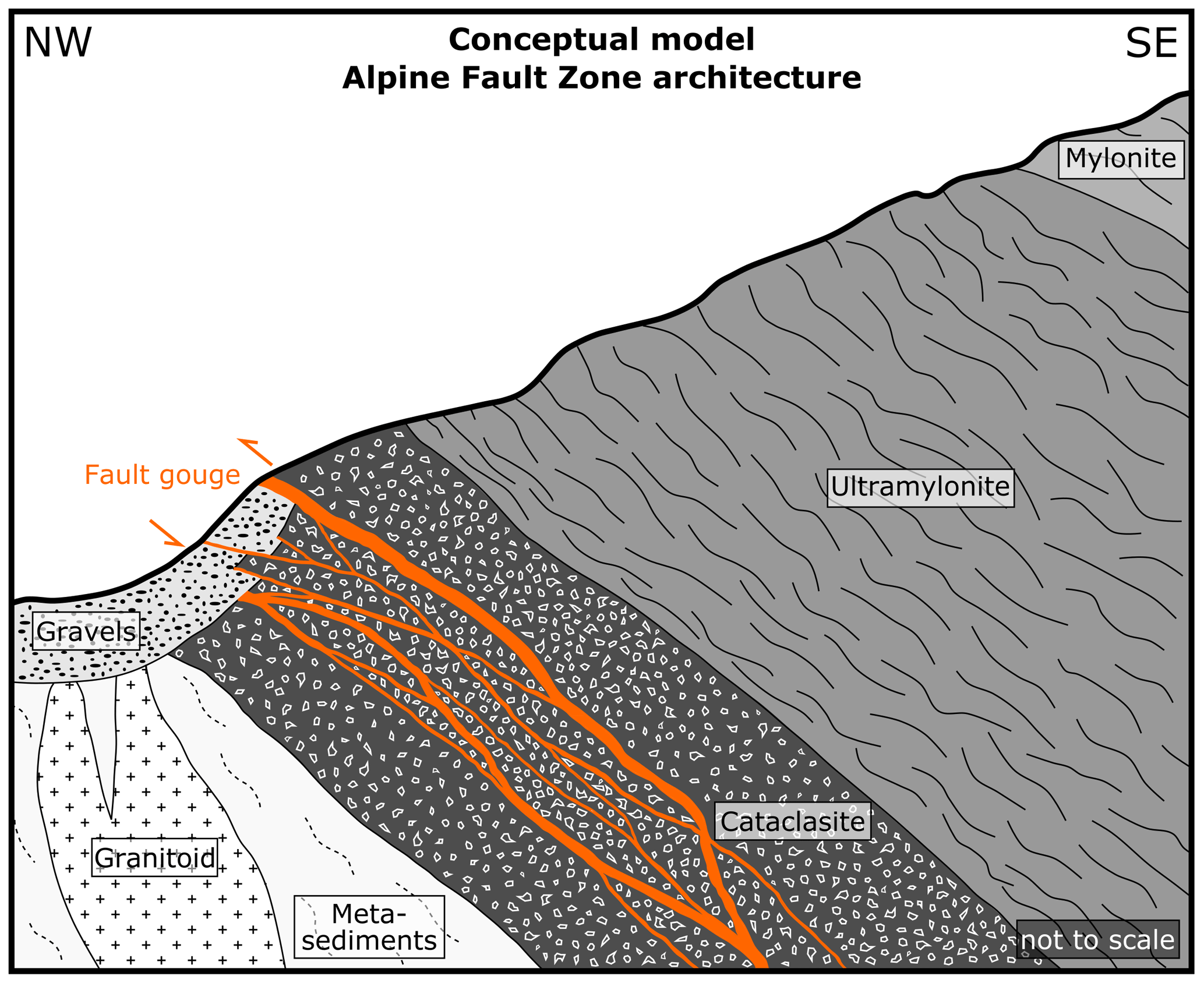
Figure 11Proposed conceptual model of the Alpine Fault Zone architecture. Multiple fault strands, with gouge thicknesses varying between a few and several tens of centimeters, accommodate displacement. Different fault gouge thicknesses represent different amounts of displacement accommodated by individual fault strands. This demonstrates the difficulty to identify the fault strand active during the last event.
Further evidence for a more complex Alpine Fault Zone architecture
This assumption of a more complex Alpine Fault Zone geometry is further supported by microstructural, mineralogical and geophysical observations to be discussed in the following. Most obviously, DFDP results promote a more complex view of the fault zone architecture of the Alpine Fault: DFDP-1B is the only location in the fault's central segment where there are two PSZs, both bound by brittle fault rocks (Fig. 3a; Sutherland et al., 2012; Toy et al., 2015). This is substantially different from other locations at the Alpine Fault, where multiple fault strands have been identified in Quaternary sediments, which are poorly consolidated and several tens of meters to a few hundred meters thick, covering the hanging wall and the footwall (Kaiser et al., 2009; Carpentier et al., 2012). The presence of these two PSZs in DFDP-1B could reflect that displacement was accommodated by more than one PSZ, which is dissimilar to the paradigm of uplift along a single fault plane (e.g., Little et al., 2005; Toy et al., 2015), and/or that one PSZ was abandoned and displacement transferred to another PSZ. Fault gouge dating could help answer this question, but is beyond the scope of this paper.
Furthermore, although the shallower DFDP-1B PSZ and the PSZ of DFDP-1A have so far been assumed to belong to the same fault plane (Fig. 3a), they exhibit different mineralogical and hence geomechanical properties (Boulton et al., 2014; Schleicher et al., 2015). This is unexpected given the close proximity of the boreholes and thus sample spacing of less than 100 m (Sutherland et al., 2012), because the distinct mineral compositions of these two PSZs represent high (DFDP-1A) and low (DFDP-1B) temperature alteration, respectively. Considering the proximity of the two drill sites, the distinct mineralogies reflecting different temperatures – and hence depths – of formation appear to go beyond what one would expect as common along-strike variation observed in the field. Similarly, although mineralogically comparable (Fig. 8), fault gouge microstructures of DFDP-1A and Gaunt Creek, also within only ∼100 m distance (Fig. 3a), differ remarkably, as exemplified by the almost completely cemented DFDP-1A PSZ compared to the PSZ at Gaunt Creek (Table ; Fig. 7e, f, k–m).
In light of this interpretation, the ∼1 cm thick, matrix clast-bearing layer sampled ∼8 cm below the PSZ at Gaunt Creek (Figs. 3d, e, 5b and 6d), which is microstructurally similar to the investigated fault gouges at Havelock Creek and Waikukupa Thrust (hanging wall-proximal layer), could be considered to constitute another PSZ of the Alpine Fault, currently starting to accommodate larger amounts of slip, or an inactive one as observed in the fault's southern segment (Barth et al., 2013).
Geometric and spatial relationships, mineralogical composition and geomechanical properties of the various (potential) PSZs at Gaunt Creek/DFDP-1 (Fig. 3a) support our hypothesis that displacement along the Alpine Fault is accommodated by more than one PSZ.
The Alpine Fault's more complex geometry: a shallow-depth phenomenon?
The multidisciplinary approach presented here reveals that the Alpine Fault Zone has a complex geometry (see Figs. 1b and 11), which is different from other quartzofeldspathic faults but typical for carbonate or phyllosilicate-hosted ones (Faulkner et al., 2003). However, it cannot be excluded that the observations we present in favor of a more complex fault zone geometry simply reflect shallow-depth phenomena like layered fault gouges do. Active seismic source investigations at the DFDP-2 site and around Haast also support a more complex fault zone model. These studies imaged a series of subparallel reflectors, interpreted as multiple fault strands (Lay et al., 2016; Lukács et al., 2018), which are comparable to those hosted by the Quaternary sediments covering the hanging wall and the footwall (Kaiser et al., 2009; Carpentier et al., 2012). There are also indications that these fault strands at the DFDP-2 site and around Haast extend into the basement. So far, it is debated if these separate fault strands are isolated or anastomosing and if they are/were active contemporaneously or consecutively (Lukács et al., 2018). Note that this structural complexity differs from the situation encountered at Waikukupa Thrust, as the second fault strand encountered at Hare Mare Creek, 700 m to the NE of this location, resulted from incision of the Waikukupa River and subsequent stress reorientation (Norris and Cooper, 1997).
Layered fault gouges reflect a structural complexity of the Alpine Fault's PSZ, which originates from shallow-depth processes. At depths where Quaternary gravels comprise the footwall, rheological contrasts resulting from the juxtaposition of these poorly consolidated and mechanically weak footwall sediments with more competent hanging wall cataclasites control the distribution of strain within the fault gouge and result in the layered structure at shallow depths. Consequently, rheological interpretations based on these rocks are biased as their microstructures mostly record modifications in just the latest part of the exhumation trajectory. These results also show that careful analyses are necessary in order to study actively exhuming fault zones and that samples should be taken at greater depths to fully investigate these kinds of faults.
Variations of PSZ fault gouge thickness among individual study sites suggest that fault rocks at these locations accommodated different amounts of displacement. Assuming that the Alpine Fault's central segment, where most of the sites are located, is activated entirely during an earthquake, these thickness variations suggest that investigated PSZs are not located on the same fault plane. This implies that multiple fault strands accommodate Alpine Fault displacement. These findings, which are based on field and microstructural analyses, are further supported by the results of the Deep Fault Drilling Project and geophysical investigations.
Consequently, these results show that the Alpine Fault Zone architecture is more appropriately described by the broad and complex conceptual model of Faulkner et al. (2003) rather than the simple single PSZ model of Caine et al. (1996).
Underlying diffractograms and supporting data of isocon analysis for this paper can be found in the Supplement.
The supplement related to this article is available online at: https://doi.org/10.5194/se-11-95-2020-supplement.
BS, CJ and VGT conducted field work and obtained the samples. Microstructures were analyzed by BS. BS and AMS performed XRD and XRF analyses. All authors contributed to manuscript preparation but BS had primary responsibility.
The authors declare that they have no conflict of interest.
We thank Stefan Gehrmann for the preparation of thin sections as well as Hartmut Liep and Marina Ospald for preparing powder samples. We would also like to thank Lina Harfenmeister and Andrea Gotsche for help with XRF and Marie Bonitz for assistance with XRD analyses. Anja Schreiber and Richard Wirth are acknowledged for TEM-foil preparation and TEM analysis, respectively. Uwe Wollenberg (EMR Group, Geological Institute, RWTH Aachen University) enabled access to and provided help with CL analyses. We are grateful to Christoph Schrank and an anonymous reviewer who stimulated fruitful discussions that helped to substantially improve the manuscript.
This research has been funded by the German Research Foundation (DFG) (grant no. JA 573/8-2). Furthermore, the project was supported by the Royal Society of New Zealand Rutherford Discovery Fellowship (RDF) (grant no. 16-UOO-1602).
The article processing charges for this open-access
publication were covered by a Research
Centre of the Helmholtz Association.
This paper was edited by Bernhard Grasemann and reviewed by Christoph Schrank and one anonymous referee.
Aksu, A., Calon, T., and Hiscott, R.: Anatomy of the North Anatolian Fault Zone in the Marmara Sea, Western Turkey: Extensional basins above a continental transform, GSA Today, 6, 3–7, 2000. a
Anders, M. and Wiltschko, D.: Microfracturing, paleostress and the growth of faults, J. Struct. Geol., 16, 795–815, 1994. a
Antonellini, M. and Aydin, A.: Effect of faulting on fluid flow in porous sandstones: Petrophysical properties, AAPG Bull., 78, 355–377, 1994. a
Barth, N., Toy, V., Langridge, R., and Norris, R.: Scale dependence of oblique plate-boundary partitioning: New insights from LiDAR, central Alpine Fault, New Zealand, Lithosphere, 4, 435–448, https://doi.org/10.1130/L201.1, 2012. a, b
Barth, N., Boulton, C., Carpenter, B., Batt, G., and Toy, V.: Slip localization on the southern Alpine Fault, New Zealand, Tectonics, 32, 620–640, https://doi.org/10.1002/tect.20041, 2013. a, b, c, d, e
Beavan, J., Ellis, S., Wallace, L., and Denys, P.: Kinematic constraints from GPS on oblique convergence of the Pacific and Australian plates, central South Island, New Zealand, in: A continental plate boundary: Tectonics at South Island, New Zealand, edited by: Okaya, D., Stern, T. A., and Davey, F., AGU Geophys. Monogr., 175, 75–94, 2007. a
Ben-Zion, Y.: Collective behavior of earthquakes and faults: Continuum-discrete transitions, progressive evolutionary changes, and different dynamic regimes, Rev. Geophys., 46, https://doi.org/10.1029/2008RG000260, 2008. a
Ben-Zion, Y. and Sammis, C.: Characterization of fault zones, Pure Appl. Geophys., 160, 677–715, 2003. a, b, c
Berryman, K., Cochran, U., Clark, K., Biasi, G., Langridge, R., and Villamor, P.: Major Earthquakes Occur Regularly on an Isolated Plate Boundary Fault, Science, 336, 1690–1693, 2012. a, b, c
Biegel, R. and Sammis, C.: Relating fault mechanics to fault zone structures, Adv. Geophys., 47, 65–111, 2004. a, b, c, d
Blenkinsop, T.: Thickness-displacement relationships for deformation zones: Discussion, J. Struct. Geol., 11, 1051–1054, 1989. a
Boese, C., Townend, J., Smith, E., and Stern, T.: Microseismicity and stress in the vicinity of the Alpine Fault, central southern Alps, New Zealand, J. Geophys. Res., 117, https://doi.org/10.1029/2011JB008460, 2012. a, b
Bohnhoff, M., Martínez-Garzón, P., Bulut, F., Stierle, E., and Ben-Zion, Y.: Maximum earthquake magnitudes along different sections of the North Anatolian Fault Zone, Tectonophysics, 674, 147–165, https://doi.org/10.1016/j.tecto.2016.02.028, 2016. a
Boulton, C., Carpenter, B., Toy, V., and Marone, C.: Physical properties of surface outcrop cataclastic fault rocks, Alpine Fault, New Zealand, Geochem. Geophy. Geosy., 13, 238–265, https://doi.org/10.1029/2011GC003872, 2012. a, b, c, d, e
Boulton, C., Moore, D., Lockner, D., Toy, V., Townend, J., and Sutherland, R.: Frictional properties of exhumed fault gouges in DFDP-1 cores, Alpine Fault, Geophys. Res. Lett., 41, 356–362, https://doi.org/10.1002/2013GL058236, 2014. a, b, c
Boutareaud, S., Calugaru, D.-G., Han, R., Fabbri, O., Mizoguchi, K., Tsutsumi, A., and Shimamoto, T.: Clay-clast aggregates: a new textural evidence for seismic fault sliding?, Geophys. Res. Lett., 35, https://doi.org/10.1029/2007GL032554, 2008. a
Brodsky, E., Gilchrist, J., Sagy, A., and Collettini, C.: Faults smooth gradually as a function of fault slip, Earth Planet. Sc. Lett., 302, 185–193, 2011. a
Bruhn, R., Parry, W., Yonkee, W., and Thompson, T.: Fracturing and hydrothermal alteration in normal fault zones, Pure Appl. Geophys., 142, 609–644, 1994. a
Bürgman, R. and Dresen, G.: Rheology of the lower crust and upper mantle: Evidence from rock mechanics, geodesy and field observations, Annu. Rev. Earth Pl. Sc., 36, 531–567, https://doi.org/10.1146/annurev.earth.36.031207.124326, 2008. a
Caine, J., Evans, J., and Forster, C.: Fault zone architecture and permeability structure, Geology, 24, 1025–1028, 1996. a, b, c, d, e, f
Carpenter, B., Kitajima, H., Sutherland, R., Townend, J., Toy, V., and Saffer, D.: Hydraulic and acoustic properties of the active Alpine Fault, New Zealand: Laboratory measurements on DFDP-1 drill core, Earth Planet. Sc. Lett., 390, 45–51, https://doi.org/10.1016/j.epsl.2013.12.023, 2014. a, b, c
Carpenter, B., Saffer, D., and Marone, C.: Composition, alteration, and texture of fault-related rocks from SAFOD core and surface outcrop analogs: evidence for deformation processes and fluid-rock interaction, Pure Appl. Geophys., 172, 5273–5289, https://doi.org/10.1002/2015JB011963, 2015. a
Carpentier, S., Green, A., Langridge, R., Boschetti, S., Doetsch, J., Abächerli, A., Horstmeyer, H., and Finnemore: Flower structures and Riedel shears at a step over zone along the Alpine Fault (New Zealand) inferred from 2D and 3D GPR images, J. Geophys. Res., 117, https://doi.org/10.1029/2011JB008749, 2012. a, b
Chester, F. and Logan, J.: Implications for mechanical properties of brittle faults from observations of the Punchbowl Fault Zone, California, Pure Appl. Geophys., 124, 79–106, 1986. a
Chester, F., Evans, J., and Biegel, R.: Internal structure and weakening mechanisms of the San Andreas Fault, J. Geophys. Res., 98, 771–786, 1993. a, b, c, d
Chester, J., Chester, F., and Kronenberg, A.: Fracture surface energy of the Punchbowl Fault, San Andreas System, Nat. Lett., 437, 133–136, https://doi.org/10.1038/nature03942, 2005. a, b
Columbus, J., Sirguey, P., and Tenzer, R.: A free fully assessed 15 meter digital elevation model for New Zealand, Survey Quarterly, 66, 16–19, 2011. a
Cooper, A. and Norris, R.: Estimates for the timing of the last coseismic displacement on the Alpine Fault, northern Fiordland, New Zealand, New Zeal. J. Geol. Geop., 33, 303–307, 1990. a, b
Cooper, A. and Norris, R.: Inverted metamorphic sequences in Alpine Fault mylonites produced by oblique shear within a plate boundary fault zone, New Zealand, Geology, 39, 1023–1026, 2011. a, b
Cowan, D., Cladouhos, T., and Morgan, J.: Structural geology and kinematic history of rocks formed along low-angle normal faults, Death Valley, California, GSA Bull., 115, 1230–1248, 2003. a, b, c, d
Cox, S., Etheridge, M., and Wall, V.: The role of fluids in syntectonic mass transport and the localization of metamorphic vein-type ore deposits, Ore Geol. Rev., 2, 65–86, 1986. a
Czaplinska, D., Piazolo, S., and Zibra, I.: The influence of phase and grain size distribution on the dynamics of strain localization in polymineralic rocks, J. Struct. Geol., 72, 15–32, https://doi.org/10.1016/j.jsg.2015.01.001, 2015. a
DeMets, C., Gordon, R., and Argus, D.: Geologically current plate motion, Geophys. J. Int., 181, 1–80, https://doi.org/10.1111/j.1365-246X.2009.04491.x, 2010. a
Döbelin, N. and Kleeberg, R.: Profex: A graphical user interface for the Rietveld refinement program BGMN, J. Appl. Crystallogr., 48, 1573–1580, 2015. a
Dolejš, D. and Manning, C.: Thermodynamic model for mineral solubility in aqueous fluids: theory, calibration and application to model fluid-flow systems, Geofluids, 10, 20–40, https://doi.org/10.1111/j.1468-8123.2010.00282.x, 2010. a
Edbrooke, S. W., Heron, D. W., Forsyth, P. J., and Jongens, R.: Geological Map of New Zealand 1:1,000,000, GNS Science Geological Map 2, 2 print maps, Lower Hut, New Zealand, GNS Science, 2015. a
Eguchi, R., Goltz, J., Taylor, C., Chang, S., Flores, P., Johnson, L., Seligson, H., and Blais, N.: Direct economic losses in the Northridge Earthquake: A three-year post-event perspective, Earthq. Spectra, 14, 245–264, 1998. a
Evans, J.: Thickness-displacement relationships for fault zones, J. Struct. Geol., 12, 1061–1065, 1990. a, b, c
Fagereng, A., Remitti, F., and Sibson, R.: Shear veins observed within anisotropic fabric at high angles to the maximum compressive stress, Nat. Geosci., 3, 482–485, 2010. a
Faulkner, D., Lewis, A., and Rutter, E.: On the internal structure and mechanics of large strike-slip fault zones: field observations of the Carboneras Fault in southeastern Spain, Tectonophysics, 367, 235–251, https://doi.org/10.1016/S0040-1951(03)00134-3, 2003. a, b, c, d, e, f, g, h, i
Faulkner, D., Mitchell, T., Healy, D., and Heap, M.: Slip on “weak” faults by the rotation of regional stress in the fracture damage zone, Nat. Lett., 444, 922–925, https://doi.org/10.1038/nature05353, 2006. a, b
Faulkner, D., Jackson, C., Lunn, R., Schlische, R., Shipton, Z., Wibberley, C., and Withjack, M.: A review of recent developments concerning the structure, mechanics and fluid flow properties of fault zones, J. Struct. Geol., 32, 1557–1575, https://doi.org/10.1016/j.jsg.2010.06.009, 2010. a, b, c, d, e
Fossen, H.: Structural Geology, Cambridge University Press, 2nd Edn., 2016. a
Fossen, H. and Cavalcante, G.: Shear zones – A review, Earth-Sci. Rev., 171, 434–455, https://doi.org/10.1016/j.earscirev.2017.05.002, 2017. a, b
Grant, J.: The Isocon Diagram – a simple solution to Gresens' equation for metasomatic alteration, Econ. Geol., 81, 1976–1982, 1986. a, b
Grant, J.: Isocon analysis: a brief review of the method and applications, Phys. Chem. Earth, 30, 997–1004, https://doi.org/10.1016/j.pce.2004.11.003, 2005. a, b, c
Grapes, R. and Watanabe, T.: Metamorphism and uplift of Alpine Schist in the Franz Josef – Fox Glacier area of the Southern Alp, New Zealand, J. Metamor. Geol., 10, 171–180, 1992. a, b
Grapes, R., Watanabe, T., and Palmer, K.: XRF analyses of quartzofeldspathic schists and metacherts, Franz Josef – Fox Glacier area, Southern Alps of New Zealand, Victoria University of Wellington Geology Department publication, 25, 11 pp., 1982. a
Gresens, R.: Composition-volume relationships of metasomatism, Chem. Geol., 2, 47–65, 1967. a
Haines, S. and van der Pluijm, B.: Clay quantification and Ar–Ar dating of synthetic and natural gouge: Application to the Miocene Sierra Mazatán Detachment Fault, Sonora, Mexico, J. Struct. Geol., 30, 525–538, https://doi.org/10.1016/j.jsg.2007.11.012, 2008. a
Hickman, S., Sibson, R., and Bruhn, R.: Introduction to special section: mechanical involvement of fluids in faulting, J. Geophys. Res., 100, 12831–12840, 1995. a
Hobbs, B., Mühlhaus, H.-B., and Ord, A.: Instability, softening and localization of deformation, in: Deformation Mechanisms, Rheology and Tectonics, edited by: Knipe, R. J. and Rutter, E. H., Geol. Soc. Spec. Publ., 54, 143–165, 1990. a
Holdsworth, R., van Diggelen, E., Spiers, C., de Bresser, J., Walker, R., and Bowen, L.: Fault rocks from the SAFOD core samples: implications for weakening at shallow depths along the San Andreas Fault, California, J. Struct. Geol., 33, 132–144, https://doi.org/10.1016/j.jsg.2010.11.010, 2011. a
Hollingsworth, J., Ye, L., and Avouac, J.-P.: Dynamically triggered slip on a splay fault in the Mw 7.8, 2016 Kaikoura (New Zealand) earthquake, Geophys. Res. Lett., 44, 3517–3525, https://doi.org/10.1002/2016GL072228, 2017. a
Howarth, J., Cochran, U., Langridge, R., Clark, K., Fitzsimons, S., Berryman, K., Villamor, P., and Strong, D.: Past large earthquakes on the Alpine Fault: paleoseismological progress and future directions, New Zeal. J. Geol. Geophys., 61, 309–328, https://doi.org/10.1080/00288306.2018.1464658, 2018. a, b
Hull, J.: Thickness-displacement relationships for deformation zones, J. Struct. Geol., 10, 431–435, 1988. a
Janku-Capova, L., Sutherland, R., Townend, J., Doan, M.-L., Massiot, C., Coussens, J., and Célérier, B.: Fluid flux in fractured rock of the Alpine Fault hanging-wall determined from temperature logs in the DFDP-2B borehole, New Zealand, Geochem. Geophy. Geosy., 9, 2631–2646, 2018. a
Janssen, C., Laube, N., Bau, M., and Gray, D.: Fluid regime in faulting deformation of the Waratah Fault Zone, Australia, as inferred from major and minor element analyses and stable isotopic signatures, Tectonophysics, 204, 109–130, 1998. a
Janssen, C., Wirth, R., Wenk, H.-R., Morales, L., Naumann, R., Kienast, M., Song, S.-R., and Dresen, G.: Faulting processes in active faults – evidences from TCDP and SAFOD drill core samples, J. Struct. Geol., 65, 100–116, https://doi.org/10.1016/j.jsg.2014.04.004, 2014. a
Kaiser, A., Green, A., Campbell, F., Horstmeyer, H., Manukyan, E., Langridge, R., McClymont, A., Mancktelow, N., Finnemore, M., and Nobes, D.: Ultrahigh-resolution seismic reflection imaging of the Alpine Fault, New Zealand, J. Geophys. Res., 114, https://doi.org/10.1029/2009JB006338, 2009. a, b
Kirkpatrick, J., Shervais, K., and Ronayne, M.: Spatial Variation in the Slip Zone Thickness of a Seismogenic Fault, Geophys. Res. Lett., 45, 7542–7550, 2018. a, b
Laurich, B., Urai, J., and Nussbaum, C.: Microstructures and deformation mechanisms in Opalinus Clay: insights from scaly clay from the Main Fault in the Mont Terri Rock Laboratory (CH), Solid Earth, 8, 27–44, https://doi.org/10.5194/se-8-27-2017, 2017. a
Laurich, B., Urai, J., Vollmer, C., and Nussbaum, C.: Deformation mechanisms and evolution of the microstructure of gouge in the Main Fault in Opalinus Clay in the Mont Terri Rock Laboratory (CH), Solid Earth, 9, 1–24, https://doi.org/10.5194/se-9-1-2018, 2018. a
Lay, V., Buske, S., Lukács, A., Gorman, A., Bannister, S., and Schmitt, D.: Advanced seismic imaging techniques characterize the Alpine Fault at Whataroa (New Zealand), J. Geophys. Res.-Sol. Ea., 121, 8792–8812, https://doi.org/10.1002/2016JB013534, 2016. a
Li, H., Wang, H., Xu, Z., Si, J., Pei, J., Li, T., Huang, Y., Song, S.-R., Kuo, L.-W., Sun, Z., Chevalier, M.-L., and Liu, D.: Characteristics of the fault-related rocks, fault zones and the principal slip zone in the Wenchuan Earthquake Fault Scientific Drilling Project Hole-1 (WFSD-1), Tectonophysics, 584, 23–42, https://doi.org/10.1016/j.tecto.2012.08.021, 2013. a
Lindsey, E., Fialko, Y., Bock, Y., Sandwell, D., and Bilham, R.: Localized and distributed creep along the southern San Andreas Fault, J. Geophys. Res.-Sol. Ea., 119, 7909–7922, https://doi.org/10.1002/2014JB011275, 2014. a
Little, T., Cox, S., Vry, J., and Batt, G.: Variations in exhumation level and uplift rate along the oblique-slip Alpine Fault, central Southern Alps, New Zealand, GSA Bull., 117, 707–723, https://doi.org/10.1130/B25500.1, 2005. a, b, c, d, e
Lockner, D., Morrow, C., Moore, D., and Hickman, S.: Low strength of deep San Andreas Fault gouge from SAFOD core, Nature, 472, 82–86, https://doi.org/10.1038/nature09927, 2011. a
Lukács, A., Gorman, A., and Norris, R.: Quaternary structural and paleo-environmental evolution of the Alpine Fault near Haast, New Zealand, from 2D seismic reflection and gravity data, New Zeal. J. Geol. Geophys., 31, 181–213, https://doi.org/10.1080/00288306.2018.1544153, 2018. a, b, c
Ma, K., Tanaka, H., Song, S.-R., Wang, C.-Y., Hung, J.-H., Tsai, Y.-B., Mori, J., Song, Y., Yeh, E., Soh, W., Sone, H., Kuo, L.-W., and Wu, H.-Y.: Slip zone and energetics of a large earthquake from the Taiwan Chelungpu-fault Drilling Project, Nature, 444, 473–475, https://doi.org/10.1038/nature05253, 2006. a
Martínez-Garzón, P., Bohnhoff, M., Ben-Zion, Y., and Dresen, G.: Scaling of maximum observed magnitudes with geometrical and stress properties of strike-slip faults, Geophys. Res. Lett., 42, 10230–10238, https://doi.org/10.1093/gji/ggx169, 2015. a
Massiot, C., Célérier, B., Doan, M.-L., Little, T., Townend, J., McNamara, D., Williams, J., Schmitt, D., Toy, V., Sutherland, R., Janku-Capova, L., Upton, P., and Pezard, P.: The Alpine Fault hanging-wall viewed from within: Structural analysis of ultrasonic image logs in the DFDP-2B borehole, New Zealand, Geochem. Geophy. Geosy., 19, 2492–2515, https://doi.org/10.1029/2017GC007368, 2018. a, b
Menzies, C., Teagle, D., Niedermann, S., Cox, S., Craw, D., Zimmer, M., Cooper, M., and Erzinger, J.: Frictional strength of wet and dry montmorillonite, Earth Planet. Sc. Lett., 455, 125–135, https://doi.org/10.1016/j.epsl.2016.03.046, 2016. a, b, c
Mitchel, T. and Faulkner, D.: The nature and origin of off-fault damage surrounding strike-slip fault zones with a wide range of displacements: A field study from the Atacama fault system, northern Chile, J. Struct. Geol., 31, 802–816, 2009. a
Moore, D. and Lockner, D.: Friction of smectite clay montmorillonite, in: The Seismogenic Zone of Subduction Thrust Faults, Columbia University Press, 317–345, 2007. a
Moore, D. and Reynolds Jr., R.: X-Ray Diffraction and the Identification of clay Minerals, Oxford University Press, Oxford, 396 pp., 1997. a, b
Moore, D., Lockner, D., Shengli, M., Summers, R., and Byerlee, J.: Strength of serpentinite gouges at elevated temperatures, J. Geophys. Res., 102, 14787–14801, https://doi.org/10.1029/2010GL046129, 1997. a
Nardini, L., Rybacki, E., Döhmann, M., Morales, L., Brune, S., and Dresen, G.: High-temperature shear zone formation in Carrara marble: The effect of loading conditions, Tectonophysics, 749, 120–139, https://doi.org/10.1016/j.tecto.2018.10.022, 2018. a
Nicol, A., Robinson, R., Van Dissen, R., and Harvison, A.: Variability of recurrence interval and single-event slip for surface-rupturing earthquakes in New Zealand, New Zeal. J. Geol. Geophys., 59, 97–116, https://doi.org/10.1080/00288306.2015.1127822, 2016. a
Norris, R. and Cooper, A.: Origin of small-scale segmentation and transpressional thrusting along the Alpine Fault, New Zealand, GSA Bull., 107, 231–240, 1995. a
Norris, R. and Cooper, A.: Erosional control on the structural evolution of a transpressional thrust complex on the Alpine Fault, New Zealand, J. Struct. Geol., 19, 1323–1342, 1997. a, b, c
Norris, R. and Cooper, A.: Late Quaternary slip rates and slip partitioning on the Alpine Fault, New Zealand, J. Struct. Geol., 23, 507–520, https://doi.org/10.1002/2016JB013658, 2000. a
Norris, R. and Cooper, A.: Very high strains recorded in mylonites along the Alpine Fault, New Zealand: Implications for the deep structure of plate boundary faults, J. Struct. Geol., 25, 2141–2157, 2003. a
Norris, R. and Cooper, A.: The Alpine Fault, New Zealand: Surface geology and field relationships, in: A continental plate boundary: Tectonics at South Island, New Zealand, edited by: Okaya, D., Stern, T. A., and Davey, F., AGU Geophys. Monogr., 175, 157–175, 2007. a, b, c, d, e
Norris, R. and Toy, V.: Continental transforms: A view from the Alpine Fault, J. Struct. Geol., 64, 3–31, https://doi.org/10.1016/j.jsg.2014.03.003, 2014. a, b
Passchier, C. and Trouw, R.: Microtectonics, Springer, 2nd Edn., 2005. a
Peacock, D., Nixon, C., Rotevatn, A., Sanderson, D., and Zuluaga, L.: Glossary of fault and other fracture networks, J. Struct. Geol., 92, 12–29, https://doi.org/10.1016/j.jsg.2016.09.008, 2016. a
Reed, J.: Myonites, cataclasites, and associated rocks along the Alpine Fault, South Island, New Zealand, New Zeal. J. Geol. Geophys., 7, 645–684, https://doi.org/10.1080/00288306.1964.10428124, 1964. a
Roser, B. and Cooper, A.: Geochemistry and terrane affiliation of Haast schist from the western southern Alps, New Zealand, New Zeal. J. Geol. Geophys., 33, 1–10, https://doi.org/10.1080/00288306.1990.10427567, 1990. a, b
Rybacki, E., Janssen, C., Wirth, R., Chen, K., Wenk, H.-R., Stromeyer, D., and Dresen, G.: Low-temperature deformation in calcite veins of SAFOD core samples (San Andreas Fault) – microstructural analysis and implications for fault rheology, Tectonophysics, 509, 107–119, https://doi.org/10.1016/j.tecto.2011.05.014, 2011. a
Rybacki, E., Morales, L., Naumann, M., and Dresen, G.: Strain localization during high temperature creep of marble: The effect of inclusions, Tectonophysics, 634, 182–197, https://doi.org/10.1016/j.tecto.2014.07.032, 2014. a
Sagy, A. and Brodsky, E.: Geometric and rheological asperities in an exposed fault zone, J. Geophys. Res., 114, https://doi.org/10.1029/2008JB005701, 2009. a, b, c, d
Sahin, M. and Tari, E.: The August 17 Kocaeli and the November 12 Düzce earthquakes in Turkey, Earth Planet. Space, 52, 753–757, https://doi.org/10.1016/j.tecto.2011.05.014, 2000. a
Schindelin, J., Arganda-Carreras, I., Frise, E., Kaynig, V., Longair, M., Pietzsch, T., Preibisch, S., Rueden, C., Saalfeld, S., Schmid, B., Tinevez, J.-Y., White, D., Hartenstein, V., Eliceiri, K., Tomancak, P., and Cardona, A.: Fiji: an open-source platform for biological-image analysis, Nat. Method., 9, 676–682, 2012. a
Schleicher, A., van der Pluijm, B., and Warr, L. N.: Nanocoatings of clay and creep of the San Andreas Fault at Parkfield, Geology, 38, 667–670, https://doi.org/10.1130/G31091.1, 2010. a
Schleicher, A., Sutherland, R., Townend, J., Toy, V., and van der Pluijm, B.: Clay mineral formation and fabric development in the DFDP-1B borehole, central Alpine Fault, New Zealand, New Zeal. J. Geol. Geophys., 58, 13–21, https://doi.org/10.1080/00288306.2014.979841, 2015. a, b, c
Schneider, C., Rasband, W., and Eliceiri, K.: NIH Image to ImageJ: 25 years of image analysis, Nat. Method., 9, 671–675, 2012. a
Scholz, C.: Wear and gouge formation in brittle faulting, Geology, 15, 493–495, 1987. a
Schrank, C., Handy, M., and Fusseis, F.: Multiscaling of shear zones and the evolution of the brittle-to-viscous transition in continental crust, J. Geophys. Res., 113, https://doi.org/10.1029/2006JB004833, 2008. a, b, c, d, e
Schuck, B., Janssen, C., Schleicher, A., Toy, V., and Dresen, G.: Microstructures imply cataclasis and authigenic mineral formation control geomechanical properties of New Zealand's Alpine Fault, J. Struct. Geol., 110, 172–186, 2018. a, b, c, d, e, f, g, h, i, j, k, l, m, n
Scott, J., Auer, A., Muhling, J., Czertowicz, T., Cooper, A., Billia, M., and Kennedy, A.: New P-T and U-Pb constraints on Alpine Schist metamorphism in south Westland, New Zealand, New Zeal. J. Geol. Geophys., 58, 385–397, https://doi.org/10.1080/00288306.2015.1093005, 2015. a, b, c
Segall, P. and Pollard, D.: Nucleation and growth of strike slip faults in granite, J. Geophys. Res., 88, 555–568, https://doi.org/10.1080/00288306.2015.1093005, 1983. a
Shervais, K. and Kirkpatrick, J.: Smoothing and re-roughening processes: The geometric evolution of a single fault zone, J. Struct. Geol., 98, 130–143, 2016. a
Sibson, R.: A note on fault reactivation, J. Struct. Geol., 7, 751–754, 1985. a
Sibson, R.: Thickness of the Seismic Slip Zone, B. Seismol. Soc. Am., 93, 1169–1178, 2003. a, b, c
Sibson, R., White, S., and Atkinson, B.: Fault rock distribution and structure within the Alpine Fault Zone: A preliminary account, in: The origin of the Southern Alps, edited by: Walcott, R. I. and Cresswell, M., B. Roy. S. NZ, 18, 55–65, 1979. a, b, c
Spandler, C., Worden, K., Arculus, R., and Eggins, S.: Igneous rocks of the Brook Street Terrane, New Zealand: implications for Permian tectonics of eastern Gondwana and magma genesis in modern intra-oceanic volcanic arcs, New Zeal. J. Geol. Geophys., 48, 167–183, 2005. a, b, c
Stern, T., Kleffmann, S., Okaya, D., Scherwath, M., and Bannister, S.: Low seismic-wave speeds and enhanced fluid pressure beneath the Southern Alps of New Zealand, Geology, 29, 679–682, 2001. a
Sutherland, R., Eberhart-Phillips, D., Harris, R., Stern, T., Beavan, J., Ellis, S., Henrys, S., Cox, S., Norris, R., Berryman, K., Townend, J., Bannister, S., Pettinga, J., Leitner, B., Wallace, L., Little, T., Cooper, A., Yetton, M., and Stirling, M.: Do great earthquakes occur on the Alpine Fault in central South Island, New Zealand?, in: A continental plate boundary: Tectonics at South Island, New Zealand, edited by: Okaya, D., Stern, T. A., and Davey, F., AGU Geophys. Monogr., 175, 235–251, 2007. a, b, c, d, e, f
Sutherland, R., Toy, V., Townend, J., Cox, S., Eccles, J., Faulkner, D., Prior, D., Norris, R., Mariani, E., Boulton, C., Carpenter, B., Menzies, C., Little, T., Hasting, M., De Pascale, G., Langridge, R., Scott, H., Lindroos, Z., Fleming, B., and Kopf, A.: Drilling reveals fluid control on architecture and rupture of the Alpine Fault, New Zealand, Geology, 40, 1143–1146, https://doi.org/10.1130/G33614.1, 2012. a, b, c, d, e, f, g, h, i, j, k, l, m, n
Sutherland, R., Townend, J., Toy, V., Allen, M., Baratin, L., Barth, N., Becroft, L., Benson, L., Boese, C., Boles, A., Boulton, C., Capova, L., Carpenter, B., Célérier, B., Chamberlain, C., Conze, R., Cooper, A., Coussens, J., Coutts, A., Cox, S., Craw, L., Doan, M., Eccles, J., Faulkner, D., Grieve, J., Grochowski, J., Gulley, A., Henry, G., Howarth, J., Jacobs, K., Jeppson, T., Kato, N., Keys, S., Kirilova, M., Kometani, Y., Kovacs, A., Langridge, R., Lin, W., Little, T., Mallyon, D., Mariani, B., Marx, R., Massiot, C., Mathewson, L., Melosh, B., Menzies, C., Moore, J., Morales, L., Morgan, C., Mori, H., Niemeijer, A., Nishikawa, O., Nitsch, O., Paris Cavailhès, J., Pooley, B., Prior, D., Pyne, A., Sauer, K., Savage, M., Schleicher, A., Schmitt, D., Shigematsu, N., Taylor-Offord, S., Tobin, H., Upton, P., Valdez, R., Weaver, K., Wiersberg, T., Williams, J., Yeo, S., and Zimmer, M.: Deep Fault Drilling Project (DFDP), Alpine Fault Boreholes DFDP-2A and DFDP-2B Technical Completion Report, GNS Science Report 2015/50, 269 pp., 2015. a
Sutherland, R., Townend, J., Toy, V., Upton, P., Coussens, J., Allen, M., Baratin, L.-M., Barth, N., Becroft, L., Boese, C., Boles, A., Boulton, C., Broderick, N., Janku-Capova, L., Carpenter, B., Célérier, B., Chamberlain, C., Cooper, A., Coutts, A., Cox, S., Craw, L., Doan, M.-L., Eccles, J., Faulkner, D., Grieve, J., Grochowski, J., Gulley, A., Hartog, A., Howarth, J., Jacobs, K., Jeppson, T., Kato, N., Keys, S., Kirilova, M., Kometani, Y., Langridge, R., Lin, W., Little, T., Lukacs, A., Mallyon, D., Mariani, E., Massiot, C., Mathewson, L., Melosh, B., Menzies, C., Moore, J., Morales, L., Morgan, C., Mori, H., Niemeijer, A., Nishikawa, O., Prior, D., Sauer, K., Savage, M., Schleicher, A., Schmitt, D., Shigematsu, N., Taylor-Offord, S., Teagle, D., Tobin, H., Valdez, R., Weaver, K., Wiersberg, T., Williams, J., Woodman, N., and Zimmer, M.: Extreme hydrothermal conditions at an active plate-bounding fault, Nature, 545, 137–140, 2017. a
Toby, B.: R factors in Rietveld analysis: How good is good enough?, Powder Diffr., 21, 67–70, 2006. a
Toppozada, T., D.M., B., Reichle, M., and Hallstrom, C. L.: San Andreas Fault Zone, California: M ≥ 5.5 earthquake history, B. Seismol. Soc. Am., 92, 2555–2601, 2002. a
Townend, J. and Zoback, M.: How faulting keeps the crust strong, Geology, 28, 399–402, 2000. a
Townend, J., Sutherland, R., and Toy, V.: Deep Fault Drilling Project – Alpine Fault, New Zealand, Sci. Drill., 8, 75–82, 2009. a, b, c
Townend, J., Sutherland, R., Toy, V., Eccles, J., Boulton, C., Cox, S., and McNamara, D.: Late-interseismic state of a continental plate-bounding fault: Petrophysical results from DFDP-1 wireline logging and core analysis, Alpine Fault, New Zealand, Geochem. Geophy. Geosy., 14, 3801–3820, https://doi.org/10.1002/ggge.20236, 2013. a, b, c, d, e
Townend, J., Sutherland, R., Toy, V., Doan, M.-L., Célérier, B., Massiot, C., Coussens, J., Jeppson, T., Janku-Capova, L., Remaud, L., Upton, P., Schmitt, D., Williams, J., Allen, M., Baratin, L.-M., Barth, N., Becroft, L., Boese, C., Boulton, C., Broderick, N., Carpenter, B., Chamberlain, C., Cooper, A., Coutts, A., Cox, S., Craw, L., Eccles, J., Faulkner, D., Grieve, J., Grochowski, J., Gulley, A., Hartog, A., Henry, G., Howarth, J., Jacobs, K., Kato, N., Keys, S., Kirilova, M., Kometani, Y., Langridge, R., Lin, W., Little, T., Lukacs, A., Mallyon, D., Mariani, E., Mathewson, L., Melosh, B., Menzies, C., Moore, J., Morales, L., Mori, H., Niemeijer, A., Nishikawa, O., Nitsch, O., Paris, J., Prior, D., Sauer, K., Savage, M., Schleicher, A., Shigematsu, N., Taylor-Offord, S., Teagle, D., Tobin, H., Valdez, R., Weaver, K., Wiersberg, T., and Zimmer, M.: Petrophysical, geochemical, and hydrological evidence for extensive fracture-mediated fluid and heat transport in the Alpine Fault’s hanging-wall damage zone, Geochem. Geophy. Geosy., 18, 4709–4732, https://doi.org/10.1002/2017GC007202, 2017. a, b, c, d
Toy, V., Norris, R., Prior, D., Walrond, M., and Cooper, A.: How do lineations reflect the strain history of transpressive shear zones? The example of the active Alpine Fault Zone, New Zealand, J. Struct. Geol., 50, 187–198, https://doi.org/10.1016/j.jsg.2012.06.006, 2013. a
Toy, V., Boulton, C., Sutherland, R., Townend, J., Norris, R., Little, T., Prior, D., Mariani, E., Faulkner, D., Menzies, C., Scott, H., and Carpenter, B.: Fault rock lithologies and architecture of the central Alpine Fault, New Zealand, revealed by DFDP-1 drilling, Lithosphere, 7, 155–173, https://doi.org/10.1130/L395.1, 2015. a, b, c, d, e, f, g, h, i, j, k, l, m, n
Toy, V., Sutherland, R., Townend, J., Allen, M., Becroft, L., Boles, A., Boulton, C., Carpenter, B., Cooper, A., Cox, S., Daube, C., Faulkner, D., Halfpenny, A., Kato, N., Keys, S., Kirilova, M., Kometani, Y., Little, T., Mariani, E., Melosh, B., Menzies, C., Morales, L., Morgan, C., Mori, H., Niemeijer, A., Norris, R., Prior, D., Sauer, K., Schleicher, A., Shigematsu, N., Teagle, D., Tobin, H., Valdez, R., Williams, J., Yea, S., Baratin, L.-M., Barth, N., Benson, A., Boese, C., Célérier, B., Chamberlain, C., Conze, R., Coussens, J., Craw, L., Doan, M.-L., Eccles, J., Grieve, J., Grochowski, J., Gulley, A., Howarth, J., Jacobs, K., Janku-Capova, L., Jeppson, T., Langridge, R., Mallyon, D., Marx, R., Massiot, C., Mathewson, L., Moore, J., Nishikawa, O., Pooley, B., Pyne, A., Savage, M., Schmitt, D., Taylor-Offord, S., Upton, P., Weaver, K., Wiersberg, T., Zimmer, M., and DFDP-2 Science Team: Bedrock geology of DFDP-2B, central Alpine Fault, New Zealand, New Zeal. J. Geol. Geophys., 60, 497–518, https://doi.org/10.1080/00288306.2017.1375533, 2017. a, b, c, d
Twiss, R. and Moores, E.: Structural Geology, W. H. Freeman and Company, 2nd Edn., 532 pp., 2007. a, b
Upton, P., Song, B., and Koons, P.: Topographic control on shallow fault structure and strain partitioning near Whataroa, New Zealand demonstrates weak Alpine Fault, New Zeal. J. Geol. Geophys., 61, 1–8, https://doi.org/10.1080/00288306.2017.1397706, 2017. a
Van Eijs, R., Mulders, F., Nepveu, M., Kenter, C., and Scheffers, B.: Correlation between hydrocarbon reservoir properties and induced seismicity in the Netherlands, Eng. Geol., 84, 99–111, https://doi.org/19.1016/j.enggeo.2006.01.002, 2006. a
Vannucchi, P., Maltman, A., Bettelli, G., and Clennell, B.: On the nature of scaly fabric and scaly clay, J. Struct. Geol., 25, 673–688, 2003. a
Warr, L. and Cox, S.: Clay mineral transformations and weakening mechanisms along the Alpine Fault, New Zealand, in: The nature and tectonic significance of fault zone weakening, edited by: Holdsworth, R. E., Strachan, R. A., Magloughlin, J. F., and Knipe, R. J., Geol. Soc. Lond. Sp. Publ., 186, 85–101, 2001. a
Warren-Smith, E., Lamb, S., and Stern, T.: Stress field and kinematics for diffuse microseismicity in a zone of continental transpression, South Island, New Zealand, J. Geophys. Res.-Sol. Ea., 122, 2798–2811, https://doi.org/10.1002/2017JB013942, 2017. a
Wibberley, C., Yielding, G., and Di Toro, G.: Recent advances in the understanding of fault zone internal structure: a review, in: The Internal Structure of Fault Zones: Implications for Mechanical and Fluid-Flow Properties, edited by: Wibberley, C. A. J., Kurz, W., Imber, J., Holdsworth, R. E., and Collettini, C., Geol. Soc. Lond. Sp. Publ., 299, 5–33, https://doi.org/10.1144/SP299.2, 2008. a, b
Williams, J., Toy, V., Massiot, C., McNamara, D., and Wang, T.: Damaged beyond repair? Characterizing the damage zone of a fault late in its interseismic cycle, the Alpine Fault, New Zealand, J. Struct. Geol., 90, 76–94, https://doi.org/10.1016/j.jsg.2016.07.006, 2016. a, b, c, d, e, f, g, h
Williams, J., Toy, V., Smith, S., and Boulton, C.: Fracturing, fluid-rock interaction and mineralization during the seismic cycle along the Alpine Fault, J. Struct. Geol., 103, 151–166, https://doi.org/10.1016/j.jsg.2017.09.011, 2017. a
Williams, J., Toy, V., Massiot, C., McNamara, D., Smith, S., and Mills, S.: Controls on fault zone structure and brittle fracturing in the foliated hanging wall of the Alpine Fault, Solid Earth, 9, 469–489, https://doi.org/10.5194/se-9-469-2018, 2018. a, b, c, d, e
Wirth, R.: A novel technology for advanced application of micro- and nanoanalysis in geosciences and applied mineralogy, Eur. J. Mineral., 16, 863–876, https://doi.org/10.1127/0935-1221/2004/0016-0863, 2004. a
Wirth, R.: Focused Ion Beam (FIB) combined with SEM and TEM: advanced analytical tools for studies of chemical composition, microstructure and crystal structure in geomaterials on a nanometre scale, Chem. Geol., 261, 217–229, https://doi.org/10.1016/j.chemgeo.2008.05.019, 2009. a
Zoback, M., Hickman, S., and Ellsworth, W.: The role of fault zone drilling, in: Treatise on geophysics, edited by: Schubert, G., Elsevier, Amsterdam, 649–674, 2007. a