the Creative Commons Attribution 4.0 License.
the Creative Commons Attribution 4.0 License.
 | 01 Aug 2022
Progressive veining during peridotite carbonation: insights from listvenites in Hole BT1B, Samail ophiolite (Oman)
Janos L. Urai
Estibalitz Ukar
Thierry Decrausaz
Marguerite Godard
The reaction of serpentinized peridotite with CO2-bearing fluids to form listvenite (quartz–carbonate rock) requires massive fluid flux and significant permeability despite an increase in solid volume. Listvenite and serpentinite samples from Hole BT1B of the Oman Drilling Project help to understand mechanisms and feedbacks during vein formation in this process. Samples analyzed in this study contain abundant magnesite veins in closely spaced, parallel sets and younger quartz-rich veins. Cross-cutting relationships suggest that antitaxial, zoned magnesite veins with elongated grains growing from a median zone towards the wall rock are among the earliest structures to form during carbonation of serpentinite. Their bisymmetric chemical zoning of variable Ca and Fe contents, a systematic distribution of SiO2 and Fe-oxide inclusions in these zones, and cross-cutting relations with Fe oxides and Cr spinel indicate that they record progress of reaction fronts during replacement of serpentine by carbonate in addition to dilatant vein growth. Euhedral terminations and growth textures of magnesite vein fill, together with local dolomite precipitation and voids along the vein–wall rock interface, suggest that these veins acted as preferred fluid pathways allowing infiltration of CO2-rich fluids necessary for carbonation to progress. Fracturing and fluid flow were probably further enabled by external tectonic stress, as indicated by closely spaced sets of subparallel carbonate veins. Despite widespread subsequent quartz mineralization in the rock matrix and veins, which most likely caused a reduction in the permeability network, carbonation proceeded to completion within listvenite horizons.
- Article
(22777 KB) - Full-text XML
-
Supplement
(3607 KB) - BibTeX
- EndNote


Listvenites (or listwanites) are the result of large-scale fluid–rock interaction that converts serpentinized peridotite into magnesite–quartz rock due to reactive flux of CO2-bearing aqueous fluids. During this reaction, which typically occurs at low-temperature hydrothermal to sub-greenschist-facies conditions (80–350 ∘C) (Beinlich et al., 2020b, 2012; Falk and Kelemen, 2015; Johannes, 1969; Menzel et al., 2018), the rock gains more than 30 wt % CO2 and an equivalent increase in rock volume. Because of the large amount of CO2 that can be captured through this process and the fact that reaction kinetics can be fast, especially if peridotite contains brucite or remnant olivine (Kelemen et al., 2011), listvenites have attracted considerable attention as a natural analogue for carbon sequestration by mineral carbonation (Kelemen et al., 2020d; Matter and Kelemen, 2009; Power et al., 2013). The International Panel on Climate Change (IPCC) predicts that negative carbon emission techniques such as artificially enhanced mineral carbonation will become necessary even if the transition to a fossil-carbon-free economy is faster than expected (IPCC, 2021). Unfortunately, although listvenites occur in many ophiolites worldwide (e.g., Boskabadi et al., 2020; Emam and Zoheir, 2013; Hansen et al., 2005; Hinsken et al., 2017; Qiu and Zhu, 2018) and isotopic evidence suggests carbonation of serpentinized peridotite can proceed very fast in nature (Beinlich et al., 2020a), experiments have so far not been able to reproduce this reaction at a large scale and acceptable costs.
Most experimental efforts have focused on reproducing and enhancing the conditions of mineral carbonation related to hyperalkaline springs and subaerial and subaquatic weathering (Kelemen et al., 2020d; Oskierski et al., 2013; Power et al., 2013). Nonetheless, the conversion of peridotite to listvenite has higher potential for carbon sequestration in comparatively smaller rock volumes. The reasons why experimental listvenite formation at a large scale is challenging are the comparatively high temperatures (>80 ∘C, but ideally about 170–200 ∘C; Kelemen and Matter, 2008), the low permeability of ultramafic rocks, and the volumetric expansion and permeability reduction associated with conversion to magnesite and quartz (Hövelmann et al., 2013; Peuble et al., 2018; van Noort et al., 2017). Besides the necessity for a source of CO2-rich fluids, permeability reduction is likely one of the main limiting factors controlling the extent of listvenite formation in natural systems. Because natural fluids at sub-greenschist-facies conditions are typically not highly enriched in CO2, listvenite formation requires high fluid–rock ratios, which implies that permeability must be maintained or repeatedly renewed over a long period to guarantee continued fluid flux.
An ingredient that is absent in most experiments but is commonplace in nature is tectonic deformation and related deviatoric stress. Listvenites occur suspiciously often along major shear zones in various ophiolites (Ash and Arksey, 1989; Belogub et al., 2017; Menzel et al., 2018; Qiu and Zhu, 2018). In listvenites of the Samail ophiolite, Oman, ductile deformation microstructures demonstrate that deformation and carbonation were synchronous (Menzel et al., 2022), suggesting that tectonic deformation plays a key role in maintaining the permeability necessary for long-lasting reactive fluid flow. Most serpentinites and listvenites formed at T < 200 ∘C are expected to be brittle, although high fluid pressure can also lead to reaction-assisted ductile deformation at low temperature (Menzel et al., 2022). Deformation can enhance permeability by fracturing (e.g., Sibson, 1996) and grain-scale processes including dilatant granular flow and creep cavitation (e.g., Fusseis et al., 2009). Different sets of veins filled with carbonate and/or quartz are commonplace in listvenites and related carbonate-bearing serpentinites (Beinlich et al., 2020b, 2012; Hansen et al., 2005; Menzel et al., 2018), suggesting that dilatancy may be one of the main mechanisms by which carbonation of peridotite can progress.
Although early veins have been identified in listvenites of the Samail ophiolite (Beinlich et al., 2020b; Menzel et al., 2022), the role fractures and crystallization pressure played in allowing penetration of CO2-rich fluids and listvenite formation is uncertain. Here we investigate the progression of microstructures within veins formed as a result of carbonation in serpentinites and listvenites of Hole BT1B, Oman Drilling Project (International Continental Drilling Project Expedition 5057-4B), using advanced high-resolution imaging and analytical methods. This natural laboratory and unmatched sample quality offer an ideal opportunity to investigate the relative timing and sequence of fracturing and mineralization, their relationship with carbonation of the unfractured matrix, the role of replacement veining, and the evolution of porosity throughout the carbonation processes in order to evaluate whether fracturing helped accommodate volumetric expansion and increased the permeability necessary for the progression of carbonation.
Due to the high quality of the drill cores recovered at site BT1 and the interdisciplinary analysis in the framework of the Oman Drilling Project, the Samail ophiolite hosts the best-studied listvenites worldwide. In the following sections, we briefly summarize the geological setting and the most important results of previous studies on listvenites in this area.
2.1 The Samail ophiolite
The Samail ophiolite (Oman) (Fig. 1) is composed of a sequence of obducted oceanic crust (4–8 km thickness) and mantle (up to 12 km thick) with characteristics similar to fast-spreading oceanic crust in the Pacific (Hopson et al., 1981; Nicolas et al., 1996; Rioux et al., 2013). Crystallization of the oceanic crust occurred during the Cenomanian (96.4–95.5 Ma) (e.g., Coleman, 1981; Rioux et al., 2013) in a mid-ocean ridge (Boudier and Coleman, 1981; Hacker et al., 1996) or, most likely, in a supra-subduction zone setting (MacLeod et al., 2013; Pearce et al., 1981; Searle and Cox, 2002). A first stage of hot oceanic subduction, broadly coeval with or shortly after oceanic crust crystallization (Garber et al., 2020), produced greenschist to granulite facies metabasalts and minor metasediments, which were underplated as a metamorphic sole below the ophiolite and are now exposed as discontinuous layers and lenses along the basal thrust fault of the ophiolite. Different parts of the metamorphic sole record temperatures of 450–550 and 700–900 ∘C at 0.7–1.2 GPa (Kotowski et al., 2021; Soret et al., 2017). The ophiolite and metamorphic sole were emplaced by top-to-SE thrusting onto allochthonous marine sediments (the Hawasina nappes). Further shortening subsequently culminated in NE-dipping subduction and burial of the autochthonous Arabian continental margin below the Hawasina nappes and the ophiolite (81–77 Ma) (Garber et al., 2021). The deepest burial of the underthrust margin occurred at about 79 Ma (Warren et al., 2003), reaching peak metamorphic conditions of 280–360 ∘C and 0.3–1.0 GPa in rocks exposed in the Jebel Akhdar and Saih Hatat domes and 450–550 ∘C and 2.0–2.4 GPa in eclogites at As Sifah (Agard et al., 2010; Grobe et al., 2019; Miller et al., 1999; Saddiqi et al., 2006; Searle et al., 1994). After termination of obduction, N–S extension during the Maastrichtian and early Paleocene led to top-to-NNE, mostly bedding-parallel shear zones in the autochthonous units (Grobe et al., 2018, and references therein). This was followed by normal faulting, folding, and low-angle detachments in the Eocene and strike-slip faulting in the Oligocene related to the exhumation of the Jebel Akhdar and Saih Hatat anticlinoria as well as tectonic and erosional thinning of the ophiolite (e.g., Grobe et al., 2019; Mattern and Scharf, 2018, and references therein).

Figure 1Geological overview map of the Samail ophiolite (common legend in b), with locations of known listvenite occurrences (yellow stars) (after Nicolas and Boudier, 1995). (b) Detailed geological overview of the area surrounding site BT1 (after de Obeso et al., 2022, and Villey et al., 1986); (c) Vein generations in outcrop, with closely spaced narrow carbonate veins (lc1, blue dotted line) cut by cataclasite (ccl, brown–red) and quartz–carbonate veins (yellow arrows). (d) Different vein generations in listvenite boulder with exceptionally wide veins, with the vein network in the matrix resembling a mesh cut by closely spaced parallel carbonate (lc1) and later quartz–carbonate (lq4 and lc4) and dolomite veins (lc6). (e) Lithologies in Hole BT1B (Kelemen et al., 2020b).
2.2 Listvenites in the Samail ophiolite
Listvenites occur along or in close proximity to the basal thrust of the Samail ophiolite at the western contact of the Aswad massif (United Arab Emirates and northwestern Oman) and in the northern Samail massif (Fanjah region, Oman) (Glennie et al., 1974; Stanger, 1985; Wilde et al., 2002) (Fig. 1a). In the area surrounding OmanDP site BT1 in the northern Samail massif, listvenites crop out as bands that are tens of meters thick along and parallel to the contact between banded peridotites and the underlying metamorphic sole, which in turn is underlain by multiply deformed, allochthonous metasediments of the Hawasina nappes (Fig. 1b). Directly north of site BT1, these units form a broad anticline (Falk and Kelemen, 2015). Early models proposed that listvenite formation was related to sub-meteoric fluids and normal faulting during extensional tectonics in the Paleogene, after ophiolite emplacement (Nasir et al., 2007; Stanger, 1985). However, the geometry of the listvenite outcrops and evidence for ductile deformation synchronous with carbonation (Menzel et al., 2022) indicate that listvenites formed along a shallow-dipping fault zone at the interface between ophiolite, metamorphic sole, and underlying metasediments, and not along steep normal faults (Kelemen et al., 2022). Together with an imprecise internal Rb–Sr isochron age of 97 ± 29 Ma (2σ) for Cr-muscovite-bearing listvenite close to site BT1 (Falk and Kelemen, 2015), this points to listvenite formation during subduction and/or underthrusting of the Arabian continental margin below the obducting ophiolite, consistent with a deep source of CO2-bearing fluids as inferred from Sr and C stable isotope geochemistry (de Obeso et al., 2022). CO2 fluid flux and carbonation concurrent with an early reactivation of the basal ophiolite thrust fault as an extensional decollement would also be consistent with the outcrop geometry, and extensional top-to-the-NE shearing in the autochthonous carbonates below the ophiolite (64 ± 4 Ma) (Hansman et al., 2018) falls just within the 2σ margin of the Rb–Sr isochron of Falk and Kelemen (2015). However, while possible, based on the currently available data this is less likely than a subduction–obduction setting (Kelemen et al., 2022). The listvenites contain abundant veins of various generations (Fig. 1c and d) and, together with adjacent units, have been overprinted by cataclasis and sharp normal to strike-slip faults that obscure the original structures, showing that multiple brittle deformation phases occurred after listvenites formed (Menzel et al., 2020).
2.3 Serpentinites and listvenites of Hole BT1B
Hole BT1B consists in its upper part of listvenite intercalated with two serpentinite layers separated by a fault at 200 m down-hole depth from underlying greenschist-facies metamafic rocks of the metamorphic sole (Fig. 1e) (Kelemen et al., 2020b). At site BT1, magnesite predominates, while dolomite and calcite are common in listvenites further north in the Fanjah area. Clumped isotope thermometry, the presence of quartz–antigorite (± talc) intergrowths, and recrystallization microstructures of quartz after opal point to listvenite formation temperatures of 80–150 ∘C in this area (Falk and Kelemen, 2015). Estimates of vein and matrix carbonate precipitation in serpentinite and listvenite of core BT1B range from 45 ± 5 to 247 ± 52 ∘C based on clumped isotope thermometry (Beinlich et al., 2020b). The pressure and depth of listvenite formation are less well constrained. Based on data from underlying carbonate sediments (Grobe et al., 2019) and a plausible ophiolite thickness of 8–10 km, pressure was at least ∼ 0.3 GPa, while the P–T conditions recorded by the metamorphic sole set an upper bound of 0.7–1.0 GPa (Kotowski et al., 2021; Soret et al., 2017). Except for some dolomite-enriched intervals, especially close to the basal fault, most BT1B listvenites are composed of magnesite, quartz, minor Cr spinel, and locally Fe (hydr)oxides or Cr-bearing muscovite (fuchsite) (Kelemen et al., 2020b). The bulk chemistry and proportions of magnesite and quartz can vary significantly on a small scale (Okazaki et al., 2021), but at the meter scale they are consistent with overall isochemical replacement of peridotite and minor addition of fluid–mobile elements (Godard et al., 2021; Kelemen et al., 2020b). Massive listvenite domains show two main types of pervasive microstructures: (i) zoned, ellipsoidal to spheroidal magnesite particles with euhedral to dendritic habit in a finer-grained quartz matrix (Beinlich et al., 2020b; Menzel et al., 2022) and (ii) variably large quartz (± fuchsite) aggregates with microstructures resembling those of orthopyroxene or bastite surrounded by a matrix of vermicular, mesh-like magnesite–quartz intergrowths (Kelemen et al., 2020b; Menzel et al., 2022). Trace element geochemistry suggests that the protolith of the BT1B listvenites was part of the banded peridotite unit commonly found at the base of the Samail ophiolite, with compositions of fuchsite-bearing listvenite overlapping with amphibole-bearing basal lherzolite and fuchsite-free listvenite similar to the composition of refractory peridotite (Godard et al., 2021). Sr and C isotope geochemistry points to deep-sourced metamorphic fluids derived from metasediments similar to the underlying Hawasina Formation as the CO2 source (de Obeso et al., 2022).
Visual core logging by the OmanDP science team showed that veins are abundant in serpentinite and listvenite, with densities of >200 veins per meter of core for veins < 1 mm wide and 50–200 veins per meter for veins >1 mm (Kelemen et al., 2020b). In serpentinites, the vein logging team distinguished between four main vein types, with a narrow (<0.1 mm) serpentine vein network that defines a mesh texture being the earliest generation. The serpentine mesh is cut by multiple generations of serpentine veins, early carbonate–oxide veins characterized by an Fe-oxide-bearing median zone and antitaxial growth habit, and younger carbonate veins with rare quartz (Kelemen et al., 2020b). In listvenites, the vein logging team identified narrow (<0.1 mm) carbonate–oxide veins with antitaxial habit and a median line as the earliest vein generation, followed by discontinuous carbonate veins, comparatively wider carbonate–chalcedony–quartz veins (>1 mm to >1 cm), and late, partially open dolomite and/or magnesite veins (Kelemen et al., 2020b).
Based on deformation and overgrowth microstructures of folded and ductile transposed veins, Menzel et al. (2022) concluded that the early carbonate–oxide veins in listvenites formed during the incipient stage of the carbonation reaction while most of the rock was still composed of serpentine, confirming similar inferences from previous studies (Beinlich et al., 2020b; Kelemen et al., 2020b). In this study, we refine the preliminary vein classification of the core logging (see Tables 1 and 2) and investigate vein generations in detail that were directly involved in the carbonation reaction progress in order to understand the mechanisms controlling focused fluid flux, permeability, and reactivity during carbonation.
Table 1Vein classification in Hole BT1B serpentinites (ordered from relatively older to younger).
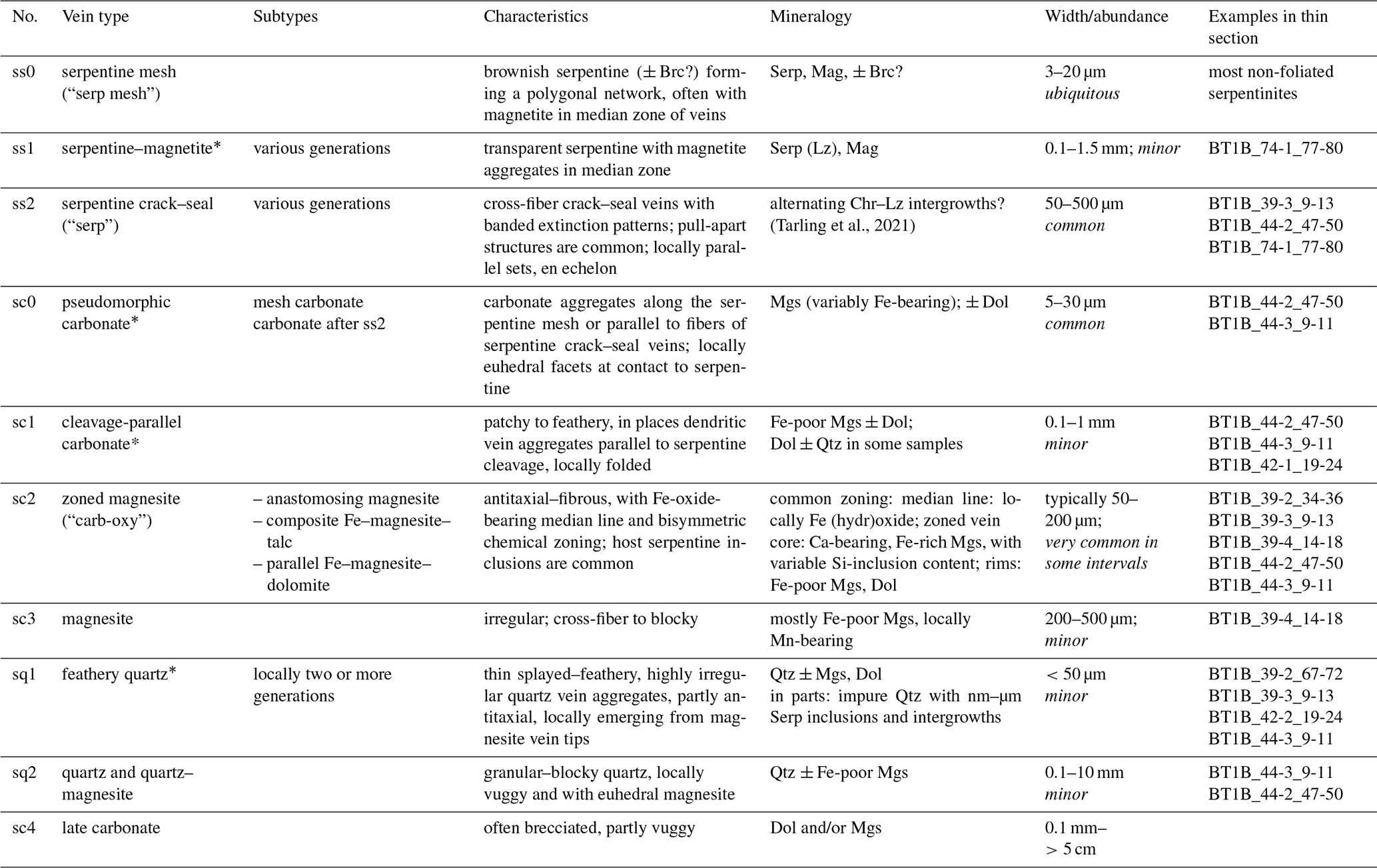
Mineral abbreviations: Mgs – magnesite, Dol – dolomite, Qtz – quartz, Tlc – talc, Serp – serpentine, Lz – lizardite, Chr – chrysotile, Brc – brucite, Mag – magnetite, Hem – hematite, CrSp – Cr spinel, FeOx – Fe oxide and/or hydroxide. * Cross-cutting relationships (relative timing) ambiguous; thin section samples are named with an abbreviated form of the ICDP convention following the scheme “Hole_Core-Section_top-bottom [cm]”.
Table 2Vein classification in Hole BT1B listvenites (ordered from relatively older to younger).
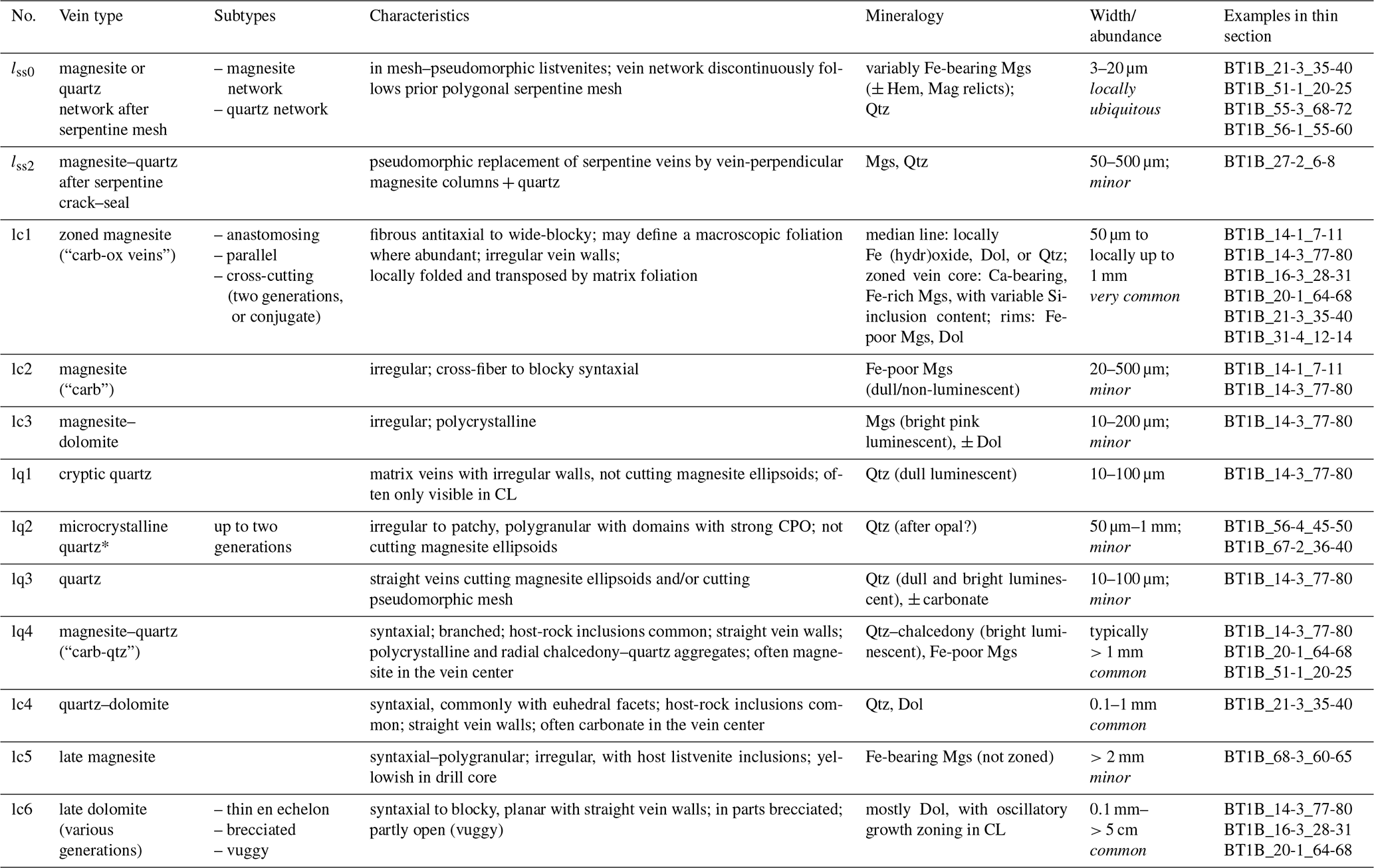
Mineral abbreviations: Mgs – magnesite, Dol – dolomite, Qtz – quartz, Tlc – talc, Serp – serpentine, Lz – lizardite, Chr – chrysotile, Brc – brucite, Mag – magnetite, Hem – hematite, CrSp – Cr spinel. Numbering of vein generations: subscripts indicate that veins are pseudomorphic replacements of previous serpentine vein generations. * Cross-cutting relationships (relative timing) ambiguous; thin section samples are named with an abbreviated form of the ICDP convention following the scheme “Hole_Core-Section_top-bottom [cm]”.
3.1 Samples
The highly variable range of (micro)structures in serpentinite and listvenite of Hole BT1B was sampled during the Oman Drilling Project Phase 1 core logging onboard R/V Chikyu in September 2017. A few additional samples from the area north and east of Hole BT1B were obtained during a field campaign in January 2020. Thin sections produced from core samples are oriented with respect to the core reference frame (CRF), an arbitrary orientation along which contiguous core sections were split. Due to the inclination of 75∘ of Hole BT1B and discontinuities across which the orientation of core sections could not be reconstructed, structural measurements and sample orientations are not easily comparable between different parts of the core. Thin sections produced from field samples were either oriented in relation to structural elements, i.e., perpendicular to foliation, or, when no foliation was visible, in the geographical reference frame. For this study, vein microstructures and cross-cutting relationships were inspected in 115 thin sections, a subset of which lacking late cataclastic overprint was investigated in more detail. Our vein classification is primarily based on listvenite samples from Hole BT1B. Thin sections and samples from BT1B are named here with an abbreviated form of the ICDP convention following the scheme “Hole_Core”-“Section_top-bottom”, with top and bottom denoting the distance (in cm) from the top of the section.
3.2 Optical and scanning electron microscopy
A PetroScan virtual polarizing microscope (ViP; RWTH Aachen University) was used to obtain high-resolution scans of full thin sections in plane-polarized light, reflected light, and at 10 different crossed polarizer orientations with a 10× objective. A high-precision automated stage allows the interpolation of the extinction behavior of each pixel to visualize extinction at all polarization angles. A selection of these digitized thin sections is publicly available as a Supplement of the Oman Drilling Project (Kelemen et al., 2020b) at http://publications.iodp.org/other/Oman/SUPP_MAT/index.html#SUPP_MAT_Z (last access: 22 July 2022). Of these, samples of special interest regarding vein microstructures are Cores 14-3 and 77-80, Cores 31-4 and 12-14, Cores 35-1 and 30-32, Cores 44-3 and 9-11, and Cores 67-2 and 36-40.
Back-scattered electron (BSE) and energy-dispersive X-ray spectroscopy (EDX) maps were acquired for phase identification and imaging of chemical zoning using a Zeiss Gemini SUPRA 55 field-emission scanning electron microscope (FE-SEM) at the Institute of Tectonics and Geodynamics of RWTH Aachen University. Whole thin sections and specific areas of interest were mapped at an acceleration voltage of 15 kV, 8.5 mm working distance, and dwell times of 0.2–1.5 ms per point. Samples were coated with a 6–8 nm thick layer of tungsten for conductivity.
We used a Zeiss Axio Scope optical microscope equipped with a “cold” cathode luminoscope CL8200 MK5-2 to obtain optical CL panorama images of large thin section areas. Single images were taken at operating conditions of 15 kV and 320–350 µA with a 10× objective and exposure times of 5–10 s.
In selected samples and areas of specific interest, panchromatic and blue-filtered SEM-CL images were obtained using a Zeiss Sigma high-vacuum FE-SEM equipped with a Gatan MonoCL4 system at the University of Texas at Austin. Following the guidelines of Ukar and Laubach (2016), carbon-coated thin sections were imaged at 5 kV accelerating voltage, 120 µm aperture, 125 µs dwell time, and 2048 × 2048 pixel resolution at magnifications up to 2500×.
One serpentinite sample with subparallel serpentine veins was prepared with broad-ion-beam (BIB) polishing to image nano-porosity in matrix and vein serpentine. For this, a mm prism was cut from a non-weathered part of the sample and mechanically pre-polished. BIB polishing was performed in a Leica TIC3X with rotary stage (RWTH Aachen) applying three Ar-ion beams for 6 h at 3 kV acceleration voltage, a beam current of 1.0 mA for each beam, and an incidence angle of 4.5∘. The tungsten-coated sample surface was imaged at high resolution (10–20 nm pixel size) in secondary electron (SE) mode using the Zeiss Gemini SUPRA 55 FE-SEM (RWTH Aachen) at an acceleration voltage of 3 kV and a working distance of 5 mm.
4.1 Veins in serpentinite
4.1.1 Serpentine mesh, magnetite–serpentine veins, and serpentine crack–seal veins
Networks of serpentine mesh veins with the typical polygonal hourglass texture of serpentinite (Wicks and Whittaker, 1977) are ubiquitous in non-foliated serpentinites (Fig. 2a; ss0 in Table 1). In these veins, serpentine is usually brownish in transmitted light, and magnetite is abundant. The serpentine mesh is cut by various generations of magnetite–serpentine veins and serpentine crack–seal veins (ss1 and ss2, Table 1; Fig. 2b and c). Similar to the serpentine mesh, magnetite–serpentine veins contain a median zone rich in magnetite with flaky to fibrous serpentine towards the vein walls. Serpentine is clear in transmitted light and the veins are discrete and continuous, occasionally forming parallel sets. Serpentine crack–seal veins are characterized by uniform to cloudy extinction under crossed polarizers with similar fiber orientations over the entire length of the vein. Commonly, these veins show vein-parallel banding with oscillatory extinction patterns that are typical of serpentine crack–seal veins (Andreani et al., 2004), likely due to alternating precipitation of chrysotile and lizardite during crack–seal cycles (Tarling et al., 2021).
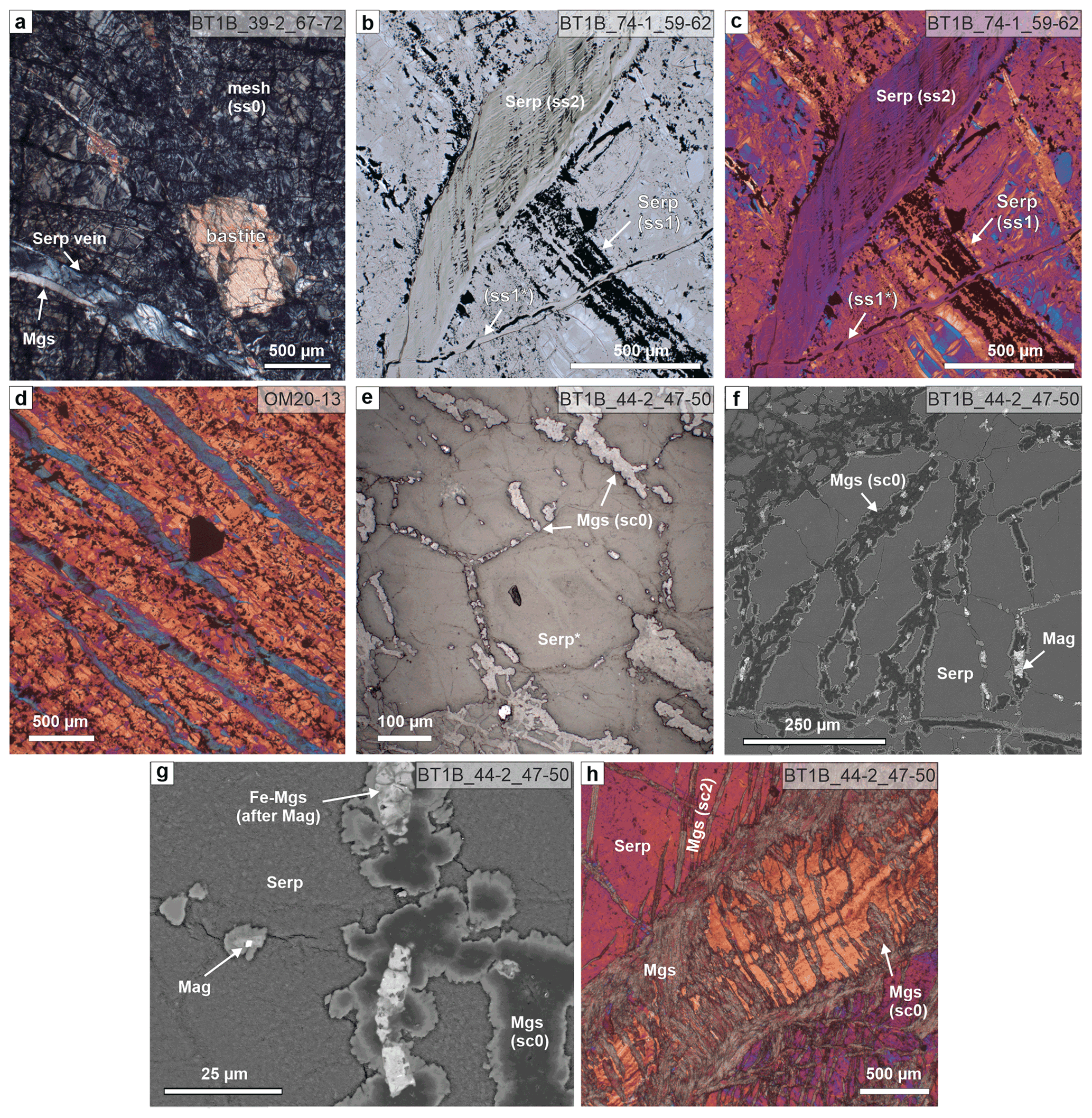
Figure 2Serpentine veins (a–d) and pseudomorphic carbonate microstructures after serpentine textures (e, f) in serpentinite. (a) Mesh (ss0) and bastite textured serpentinite cut by a serpentine vein; a magnesite vein exploits the vein–host rock interface of the serpentine vein under crossed polarizers (xpol). (b) Plane-polarized (ppol) micrograph of a wide serpentine–magnetite vein (ss1) cut by a light green, banded serpentine crack–seal vein (ss2), which is in turn cut by a narrow serpentine–magnetite vein (ss1*). (c) Same area as in (b), with xpol and 1λ plate. (d) Clustered cleavage-parallel serpentine veins in foliated serpentinite north of site BT1 with strong crystallographic preferred orientation and flattened magnetite mesh cells. The large black grain is Cr spinel (xpol with 1λ plate). (e) Reflected light image and (f) BSE image of a magnesite vein network (sc0) tracing polygonal serpentine mesh (Serp*) delineated by former magnetite in serpentinite. (g) Detailed BSE image of sc0 magnesite showing pseudomorphic replacement of magnetite by Fe magnesite (similar replacements are known from listvenites elsewhere; Menzel et al., 2018) and compositional zoning with Fe-bearing euhedral to dendritic magnesite rims. (h) Serpentine crack–seal vein (orange) in serpentinite, with partial pseudomorphic replacement by magnesite and cross-cut by zoned magnesite–dolomite veins (sc2) (xpol with 1λ plate). For abbreviations of minerals and vein generations used in all figures, see Tables 1 and 2.
Clusters of parallel, en echelon, and/or branched serpentine veins occur in foliated serpentinites of the area north of site BT1. The veins are parallel to the penetrative serpentinite foliation, which is defined by flattened mesh cells delineated by magnetite aggregates (Fig. 2d). Serpentine in these cleavage-parallel veins has the same extinction direction with the lambda plate, indicating a strong and consistent shape and crystallographic preferred orientation, which is different from the crystallographic preferred orientation of matrix serpentine (Fig. 2b).
4.1.2 Pseudomorphic carbonate
In carbonate-bearing serpentinite, small magnesite aggregates locally occur along the serpentine mesh, pseudomorphically tracing the polygonal mesh outlines (Fig. 2e, f; sc0, Table 1; Fig. S1 in the Supplement). Magnetite, partly transformed to Fe magnesite, is commonly present as inclusions within these magnesite aggregates. Pseudomorphic magnesite has core–rim zoning of variable Fe contents, and magnesite rims in the vein network commonly have euhedral crystal facets towards contacts with serpentine or a dendritic habit (Fig. 2g). In places, the pseudomorphic magnesite vein network has a preferred orientation tracing flattened serpentine mesh cells.
Pseudomorphic replacement of serpentine by carbonate also occurs within and along the walls of serpentine crack–seal veins (Fig. 2h). Here, vein-perpendicular magnesite columns locally replace serpentine along serpentine fibers.
4.1.3 Carbonate veins
Most carbonate in serpentinites of Hole BT1B is in veins and only occurs in minor amounts as dispersed grains within the serpentine matrix (Fig. 3). Besides pseudomorphic carbonate, two types of early carbonate veins dominate in serpentinite: patchy to feathery carbonate veins parallel to serpentine cleavage planes and zoned magnesite veins.
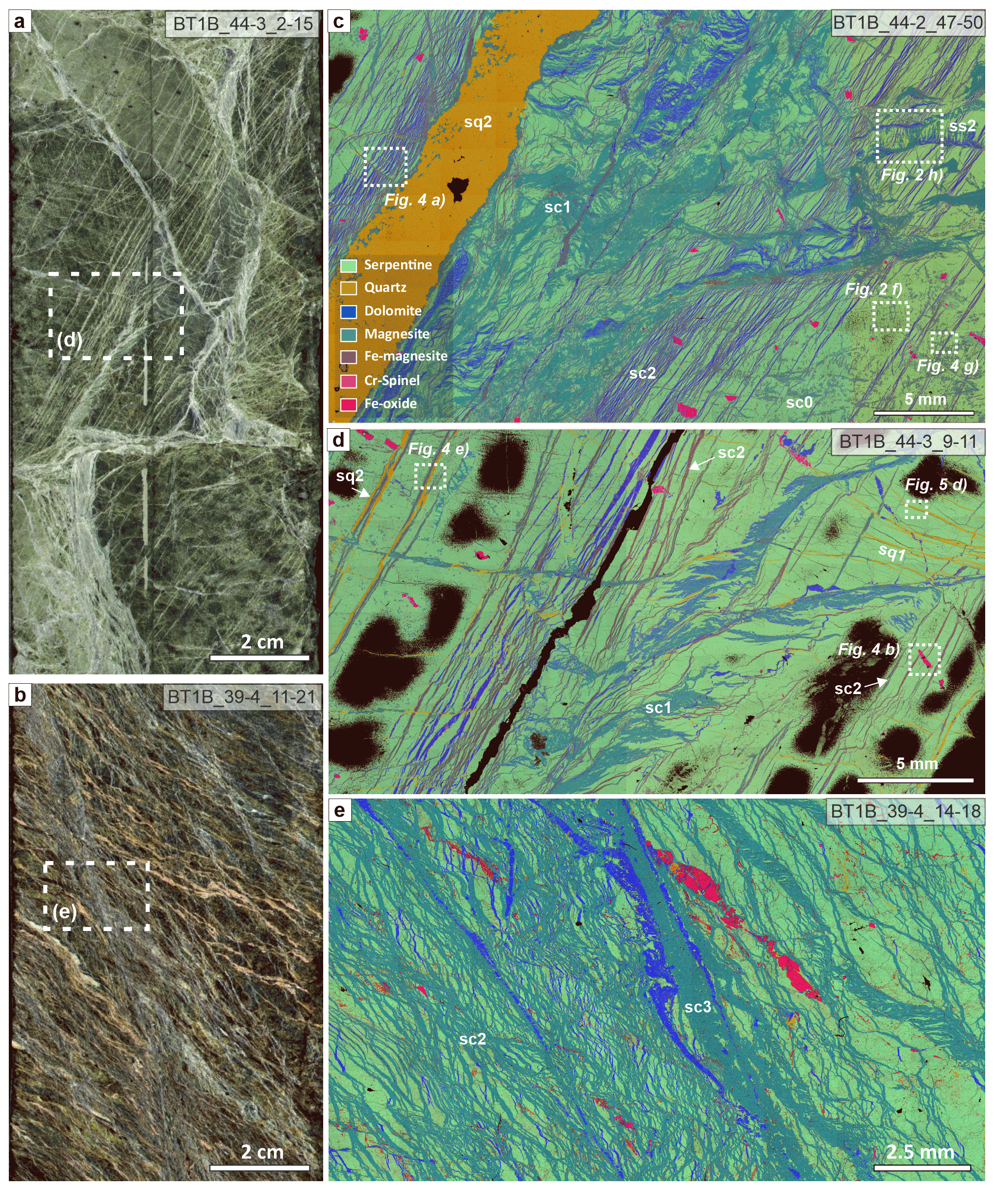
Figure 3Veins in serpentinite of Hole BT1B. (a) Split-core image of serpentinite with closely spaced, parallel carbonate veins. (b) Split-core image of strongly veined serpentinite interval with anastomosing carbonate veins. (c–e) Composite-color EDX maps of carbonate-rich serpentinites showing different carbonate (sc1–sc3) and quartz (sq1, sq2) vein generations (common legend in c). Black patches in (d) are areas where soft bastite serpentine were lost during sample preparation. Core diameter in (a) and (b) is 6.3 cm.
Cleavage-parallel carbonate veins (sc1, Table 1) have an irregular morphology with highly variable vein width and consist of Fe-poor magnesite and/or dolomite (Fig. 3c, d). These veins follow the (locally folded) serpentine cleavage and often form branched and curved, semi-isolated patches with splayed vein tips.
The most abundant carbonate vein type in serpentinite consists of zoned magnesite veins (sc2, Table 1; Fig. 3c–e). During core logging, these have been named carbonate–oxide or antitaxial carb-oxy veins (Kelemen et al., 2020b). Because an Fe-oxide median line and antitaxial texture is not always present, we hereafter refer to this vein group as zoned magnesite veins (sc2). These are characterized by a planar morphology with rather constant vein width (typically 50–200 µm) and a vein-parallel, often bisymmetrical chemical zoning from a median zone towards the vein walls (Fig. 4). The veins are mostly composed of magnesite of variable composition, but dolomite can also be present along the vein walls, and minor vein segments locally consist of (or are replaced by) dolomite and rare quartz. The type of zoning and width of different zones vary between different samples and, occasionally, within the same thin section. Where present, the median line (2–10 µm wide) consists of Fe oxide and/or soft Fe hydroxides (possibly goethite) that are rarely well preserved during thin section preparation. The median zone is commonly composed of Ca- and Fe-bearing magnesite in the center, followed by Fe-rich magnesite with systematic variations in the number of SiO2 inclusions and Fe-poor magnesite or dolomite towards the vein walls (Fig. 4d, f). Chemical zoning is not always well developed and may consist only of slight variations in the quantity of silica impurities in magnesite. Flat or lens-shaped serpentine inclusions parallel to the vein length are common. In some zoned magnesite veins from core sections of the lower part of the upper serpentinite layer (98.7–100 m down-hole depth, see Fig. 1e) seams of talc occur along the vein walls, and locally talc is present as remnant inclusions between the Fe-rich and Fe-poor magnesite zones of the veins (Fig. 4c, f).
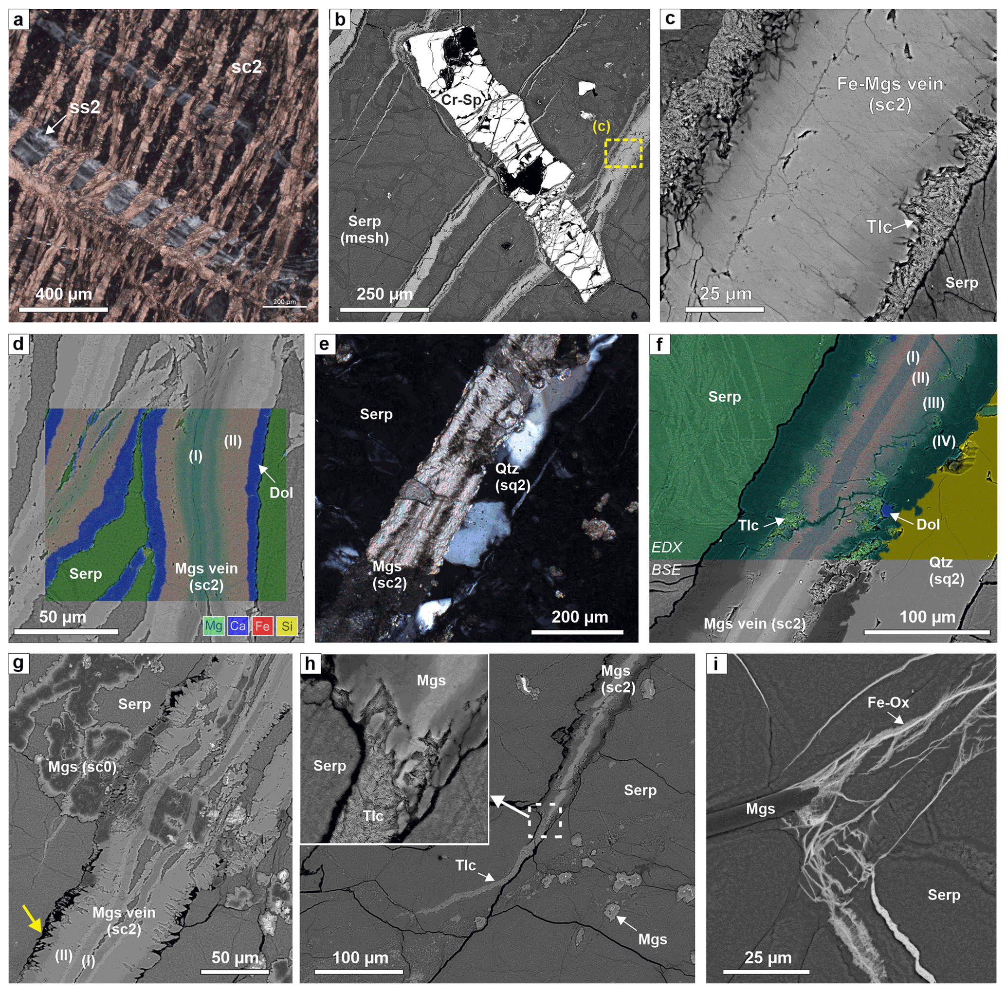
Figure 4Microstructures of zoned magnesite veins (sc2) in serpentinite. (a) Close spacing of carbonate; the veins are deflected where they cut a crack–seal serpentine vein (xpol). (b) Elongated Cr spinel and serpentine mesh cut by zoned, Fe-magnesite–talc veins (BSE image). (c) Detail of (b), showing talc seams along vein walls. (d) Composite-color EDX map superposed on a BSE image of zoned sc2 veins with dolomite rims (I: Ca-bearing magnesite; II: Fe magnesite); for phase legend see Fig. 3c. (e) Quartz vein exploiting the vein–host interface of a zoned magnesite vein (xpol). (f) Composite-color EDS map superposed on a BSE image of a part of the vein in (e), with zones of (I) Ca-bearing magnesite, (II) Fe magnesite, (III) Fe-bearing magnesite with talc inclusions, and (IV) Fe-poor magnesite. Small Mg Si variations show thin serpentine veins in the matrix. (g) Complex cross-cutting relations between a zoned sc2 vein and earlier mesh–pseudomorphic magnesite (sc0), showing that the core of sc2 veins formed by opening, while the vein rims are micro-reaction fronts with euhedral crystal terminations at the vein walls (yellow arrow). (h) Tip of a zoned sc2 carbonate vein in serpentinite. At the termination of magnesite, a talc veinlet continues over a short distance. This talc veinlet does not correspond to the open microcracks in serpentinite (black lines), showing that those are later and not related to vein formation of the zoned magnesite vein. (i) Fe-oxide and/or Fe-hydroxide veinlets emanating from the magnesite vein tip. (a, d, g: BT1B_44-2_47-50; b, c, e, g, h: BT1B_44-3_9-11; i: BT1B_39-3_9-13.)
In some serpentinite core intervals, sc2 veins form closely spaced, parallel sets (clusters) (Figs. 3; 4a). Locally, they occur as two conjugate, anastomosing sets that resemble an s–c fabric of scaly fractured serpentinite (Fig. 3b, e). Where they intersect elongated Cr-spinel grains, zoned magnesite veins branch into numerous narrow veinlets, locally fragmenting the Cr spinel (Fig. 4b). Elongated and/or flattened Cr spinel is commonly aligned, probably showing the orientation of a remnant high-temperature plastic deformation fabric of former olivine. All carbonate veins in Hole BT1B are oblique to that early fabric. No systematic relationship between sc1–sc2 vein orientations and the serpentinite mesh texture is apparent. Cross-cutting relationships between sc2 and sc1 veins are usually ambiguous because zoned magnesite veins are locally deflected along serpentine cleavages. However, sc2 veins locally branch into narrow veinlets where they transect sc1 veins, indicating that at least some sc2 veins are relatively younger.
Cross-cutting relationships between sc2 veins and mesh–pseudomorphic magnesite aggregates in the serpentinite matrix are also often complex and ambiguous. For example, Fig. 4g shows that only the median zone of the sc2 vein cuts the matrix magnesite aggregate, while the Fe-enriched magnesite zone (II) does not. Facetted crystal terminations of carbonate towards matrix serpentine are locally present along the walls of some sc2 veins (yellow arrow in Fig. 4g). Sc2 veins commonly pinch out in narrow vein tips, but abrupt, partially corroded, wide vein terminations are also present. In places, magnesite veins show narrow talc vein terminations (Fig. 4h), Fe-oxide veinlets (Fig. 4i), or feathery quartz veins (sq1, see below) that emanate from carbonate vein tips (Fig. 5a).
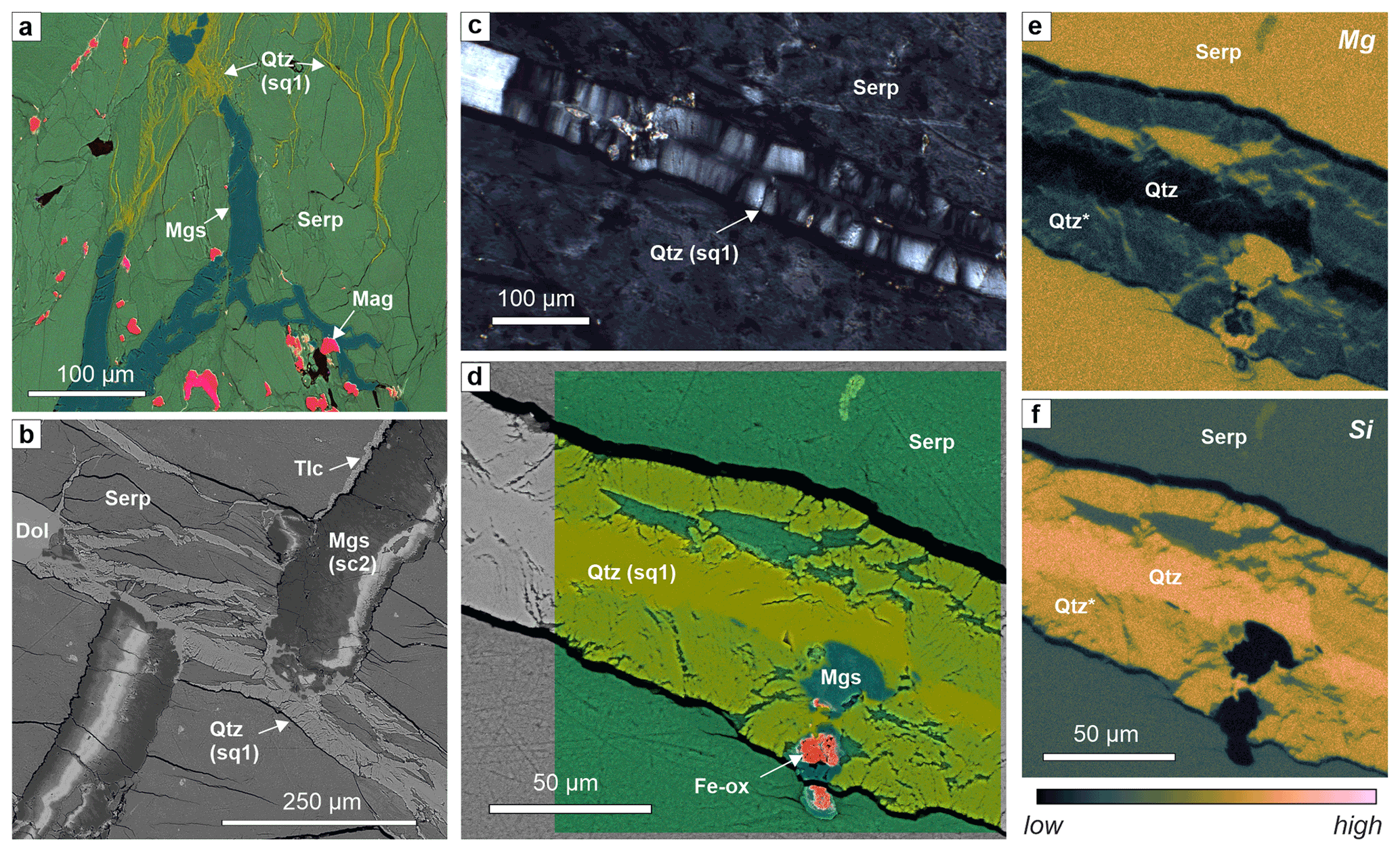
Figure 5Quartz veins in serpentinite of Hole BT1B. (a) Composite-color EDX map of feathery quartz micro-veins with interstitial serpentine emanating from magnesite vein tips (sample BT1B_39-3_9-13). (b) BSE image of a branched quartz vein with minor dolomite cutting and offsetting a zoned magnesite vein. (c) Fibrous, antitaxial microstructure of a quartz vein in serpentinite (xpol). (d–f) Composite-color EDX map superposed on a BSE image and corresponding Mg and Si maps of a quartz vein in serpentinite (common color scale shown below f), showing that only the median zone consists of pure SiO2, while the vein walls (Qtz*) contain a high amount of serpentine and, locally, carbonate (nano-) inclusions, which result in the overall chemistry of Mg-bearing quartz at the spatial resolution of the EDX measurements. (b–f) Sample BT1B_44-3_9-11.
4.1.4 Quartz veins
Quartz veins are common in the serpentinites of Hole BT1B, unlike typical serpentinites and peridotites of the Samail ophiolite where they are mostly absent. Quartz–serpentine intergrowths have previously been observed in samples near Hole BT1B (Falk and Kelemen, 2015), and a few quartz veins were logged during shipboard core description (Kelemen et al., 2020b). We note that their abundance in BT1B was underestimated during logging because they are usually narrow and easily overlooked (Fig. 5a). Two types are common: “feathery” quartz vein aggregates intergrown with serpentine at the microscale (sq1; Table 1) and wider, polygranular to blocky quartz and quartz–magnesite veins (sq2; Table 1). Cross-cutting relationships between the two types of quartz veins are ambiguous. Sq1 veins are strongly branched and locally emanating from the tips of carbonate veins (Fig. 5a). They commonly cut and may offset sc2 carbonate veins (Fig. 5b). Some wide sq1 veins (>20 µm) show an antitaxial habit, with a median zone composed of pure quartz and margins enriched in nanometer- to micrometer-sized serpentine and/or carbonate inclusions (Fig. 5c–f). Pods of dolomite or magnesite constitute parts of some veins.
Sq2 quartz and quartz–magnesite veins locally contain euhedral magnesite and are commonly oriented parallel to sc2 veins (Figs. 3d; 4e), suggesting that they formed due to preferential fracturing along the walls of zoned magnesite veins.
4.1.5 Late carbonate veins
Late, partially open or brecciated carbonate veins cut serpentinites and all previous vein generations (sc4, Table 1). These are unrelated to the formation of listvenite and possibly linked to young magnesite, dolomite, and calcite–aragonite precipitation in open joints from groundwater or hyperalkaline serpentinization fluids. Similar young carbonate veins and travertine are common in the weathering horizon of the Samail ophiolite peridotites (e.g., Chavagnac et al., 2013; Giampouras et al., 2020; Noël et al., 2018; Ternieten et al., 2021). Therefore, we do not consider them further here, but we note that they can locally obscure structures of veins synchronous with listvenite formation.
4.2 Veins in listvenite
Some listvenite intervals of Hole BT1B are highly veined such that locally >50 % of the listvenite volume consists of veins. This is the result of pseudomorphic replacement of previous serpentine veins and the superposition of veins formed at different time steps (Table 2).
4.2.1 Pseudomorphic veins after serpentine
Based on their strong microstructural resemblance to common serpentine veins in the serpentinites, we identify two types of pseudomorphic veins: pseudomorphic magnesite (and/or quartz) vein networks after serpentine mesh (lss0) and magnesite–quartz veins after serpentine crack–seal veins (lss2). Incipient stages of both pseudomorphic vein replacement microstructures are also present in carbonate-bearing serpentinite.
The mesh–pseudomorphic vein network (lss0) is most evident in listvenites where the volume between the magnesite mesh consists of monomineralic quartz (Fig. 6a). Magnesite usually has variable Fe contents, in parts tracing the former presence of magnetite in the serpentinite mesh, now mostly reacted to Fe magnesite. The vein network may show a preferred orientation, delineating elongated polygonal mesh cells. In contrast to serpentinite, wherein euhedral crystal facets of pseudomorphic carbonate are common, in listvenite single veinlets commonly have a corroded appearance or are overgrown by later generations of carbonate Fig. 6a).
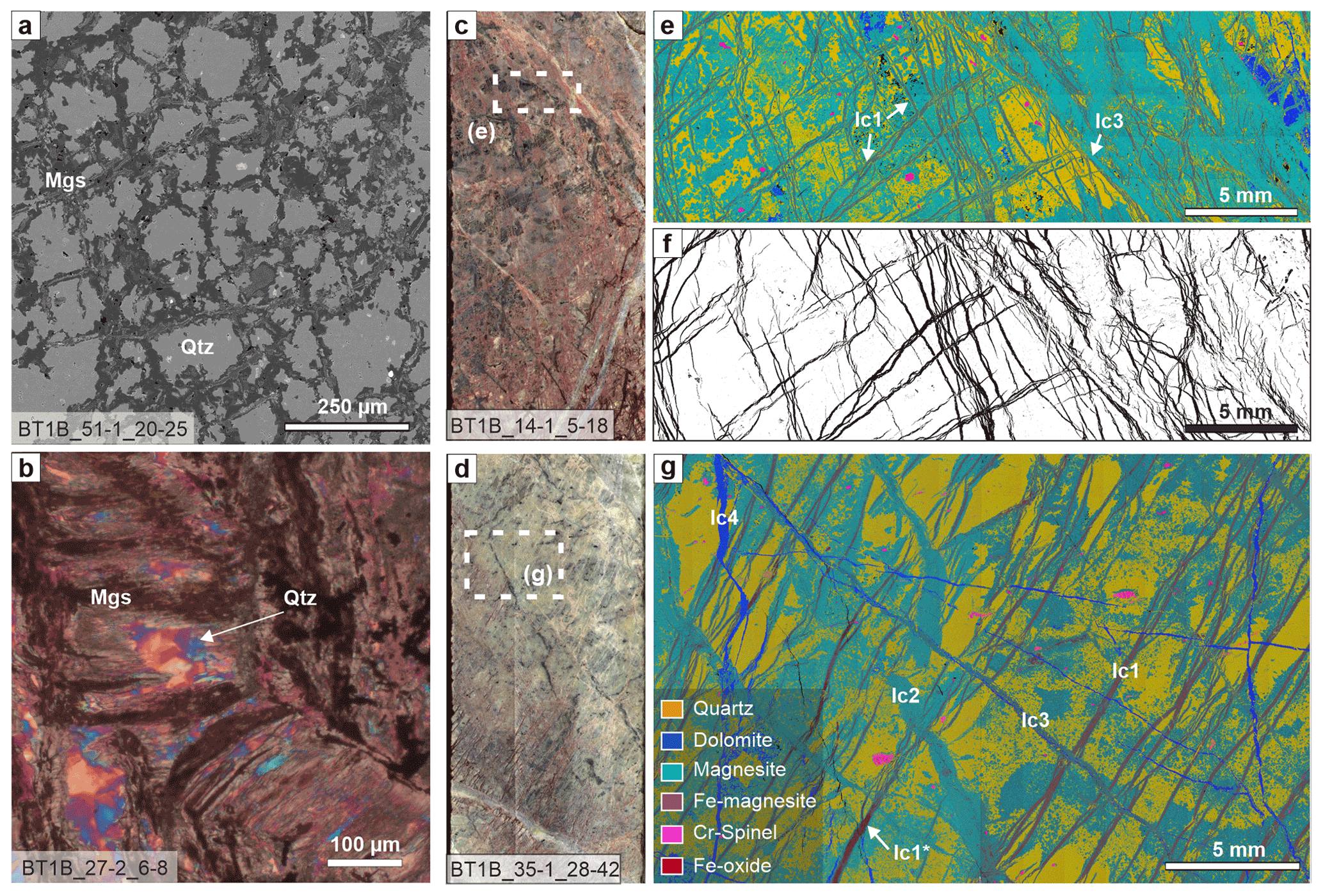
Figure 6Veins in listvenite of Hole BT1B. (a) Magnesite pseudomorphic mesh vein network (lss0, BSE image). (b) Pseudomorphic magnesite–quartz after a serpentine crack–seal vein (lss2, xpol with 1λ plate). (c) Split-core image of listvenite with a conjugate cross-cutting and locally anastomosing zoned magnesite vein network. (d) Split-core image of listvenite with parallel carbonate veins that are locally oxidized. (e) Composite-color EDX map of the indicated area in (c), showing different magnesite vein generations and a patchy quartz distribution in the matrix (common legend in g). (f) Same area as in (e), segmented for Fe magnesite (15.8 %). (g) Composite-color EDX maps of the area in (d) showing cross-cutting relationships between different carbonate vein generations (see Table 1). Dark red veins (lc1*) contain abundant Fe oxides (red veins in d). Core diameter in (a) and (d) is 6.3 cm.
Pseudomorphic magnesite–quartz veins after serpentine crack–seal veins (lss2) are characterized by irregular magnesite along vein walls and columnar to fibrous magnesite extending from the walls into the vein center (Fig. 6b; see Fig. 2h). Magnesite fibers are highly variable in length, ranging from small fractions of the vein aperture to fully bridging the vein. Quartz forms a polycrystalline, non-fibrous aggregate between the magnesite fibers. This vein microstructure is uncommon for classical antitaxial, syntaxial, or stretching veins (Bons et al., 2012), which supports the interpretation that they result from pseudomorphic replacement.
4.2.2 Early, zoned magnesite veins
Zoned magnesite veins (lc1, Table 2) are the most abundant in many listvenite core intervals (Fig. 6c–g) and occur in nearly all studied listvenite samples. As in serpentinites, they form closely spaced parallel or anastomosing branched to cross-cutting sets of fibrous to blocky veins. They show a well-defined median zone that is brown in plane-polarized light or contains Fe oxides or hydroxides and variably strong chemical zoning from the median zone towards the vein walls, indicating antitaxial growth. In most investigated thin sections, lc1 veins are the earliest generation based on cross-cutting relationships (Fig. 6e–g). In some samples, zoned magnesite veins with a wide-blocky habit form an early generation of this vein type. In some cases, wide-blocky veins are cut by fibrous carbonate veins, whereas in others fibrous segments alternate with wide-blocky sections within a single vein. Owing to these variations in texture that commonly occur together we group them into one vein type (lc1).
In listvenite samples that have a foliated matrix defined by aligned magnesite ellipsoids or dendritic magnesite–quartz intergrowths (Menzel et al., 2022), subparallel clusters of lc1 carbonate veins are oriented at various angles with respect to the matrix foliation. In samples for which the vein orientations are at a high angle to the matrix foliation, the veins are locally folded and/or transposed (Menzel et al., 2022).
Lc1 veins are mostly composed of Fe- to Ca-bearing magnesite (Fig. 7). No preserved serpentine inclusions have been observed in this type of veins, but quartz inclusions are common. In some core intervals, where these veins form anastomosing sets, vein segments composed of dolomite alternate with magnesite. The chemical zoning is similar to that of zoned magnesite veins in serpentinite (sc2) and typically bisymmetric. Lc1 veins commonly have an antitaxial habit, with elongated to fibrous crystals oriented with their long axes perpendicular to the median zone. The median zone usually shows high Fe contents ( up to 0.30 in listvenites that contain little or no hematite) near the vein center and becomes progressively Fe-poor towards the vein walls (Fig. 7b). In some veins, a zone of Ca- and Fe-bearing magnesite (XFe = 0.10–0.15) with rare quartz inclusions occurs along the center of the Fe-rich median zone. In listvenites that contain abundant hematite, Fe contents in zoned magnesite veins are comparatively low and show less variability, although systematic chemical variations are still apparent owing to variations in minor or trace Ca contents and silica inclusions (Fig. 7f). Similar silica inclusions are common in matrix magnesite of the listvenites, wherein they have been shown to consist of SiO2 nano-inclusions (Beinlich et al., 2020b; Menzel et al., 2022). Fe-enriched domains are commonly brown to red in the core and in plane-polarized light due to Fe oxides or hydroxides along the median zone. Cross-cutting relationships show that in some cases the presence of Fe oxides or hydroxides is due to oxidation of Fe magnesite after formation of the lc1 veins (red zones in Fig. 6d; lc1* in Fig. 6g).

Figure 7Zoned magnesite veins in listvenite. (a) Thin section overview of listvenite with comparatively wide, zoned Fe-magnesite veins (lc1), cut by a quartz–magnesite vein (lq3). (b) BSE image of a rim of a zoned magnesite vein, with Fe(Fe + Mg) of magnesite shown for different zones (from EDX spot measurements). (c) Crossed polarized micrograph of a zoned magnesite vein with lens-shaped host listvenite inclusions. (d) Pan-chromatic SEM-CL image of an lc1 magnesite vein with an Fe-rich median zone, concentrically zoned growth with euhedral facets towards the vein walls, and dendritic boundaries with bright luminescent SiO2 overgrowth. The matrix consists of microcrystalline quartz (lq2) (sample BT1B_67-2_36-40). (e) SEM-CL image of the area indicated in (c), showing euhedral magnesite growth towards the vein walls. (a, b, c, e) Sample BT1B_14-3_77-80). (f) BSE image and EDX maps of the dotted area of a thin zoned magnesite vein in listvenite, showing systematic variations in the number of SiO2 nano-inclusions that are apparent as variable Si-bearing magnesite at the resolution of EDX measurements (sample BT1B_27-2_6-8). Contrasts are adapted for each EDX map separately to improve visibility of zoning.
SEM-CL images reveal elongated, vein-perpendicular, Fe-rich magnesite in the vein centers (dark luminescent) and Fe-poor, lighter luminescent magnesite overgrowths towards the vein walls in crystallographic continuity (Fig. 7d). Many magnesites show euhedral terminations with concentric growth zoning away from the vein center, confirming the antitaxial nature of these veins (Fig. 7d, e). Vein boundaries are irregular with dendritic embayments that extend into the listvenite matrix. A bright luminescent SiO2 overgrowth rim separates the dendritic embayments from the quartz-rich listvenite matrix (Fig. 7d). This irregular magnesite rim with quartz overgrowth has similar microstructure, luminescence, and composition as the outermost, typically dendritic rims around matrix magnesite ellipsoids described by Menzel et al. (2022).
Cross-cutting relationships between different carbonate veins and passive markers in the form of oxide inclusions within the veins show that carbonate vein formation did not only occur by dilatancy but was accompanied by replacement of the serpentinite matrix (Fig. 8a and b). Measurement of the extent of replacement versus opening is possible in samples in which different generations of zoned magnesite veins cross-cut each other because the dilatant vein aperture is recorded by the displacement of the previous vein generation (Fig. 8b). The cumulative vein width is typically more than twice the opening aperture, showing that epitaxial carbonate growth by replacement of serpentine accounts for much of the vein volume. Moreover, Fe oxides within Fe3+-rich listvenite samples and systematic variations in the content of SiO2 may act as passive markers that document vein growth by replacement (Fig. 8c–e). While hematite may have co-precipitated during serpentine replacement, magnetite (see yellow arrow in Fig. 8d) is a remnant of the prior serpentinization stage and thus a passive marker. Fe oxides are only cut by dolomite- and quartz-bearing median lines, and oxide aggregates are preferentially aligned oblique to the lc1 carbonate veins, recording a previous fabric that appears mostly unaffected by veining. Similarly, many magnetite aggregates were passively overgrown during expansion of carbonate veins. Notably, magnesite ellipsoids in the listvenite matrix have the same, albeit concentric, patterns of silica zoning and similar cross-cutting relationships with Fe oxides (Fig. 8c), indicating that this stage of carbonate growth proceeded similarly and simultaneously in ellipsoidal matrix grains and along vein rims.
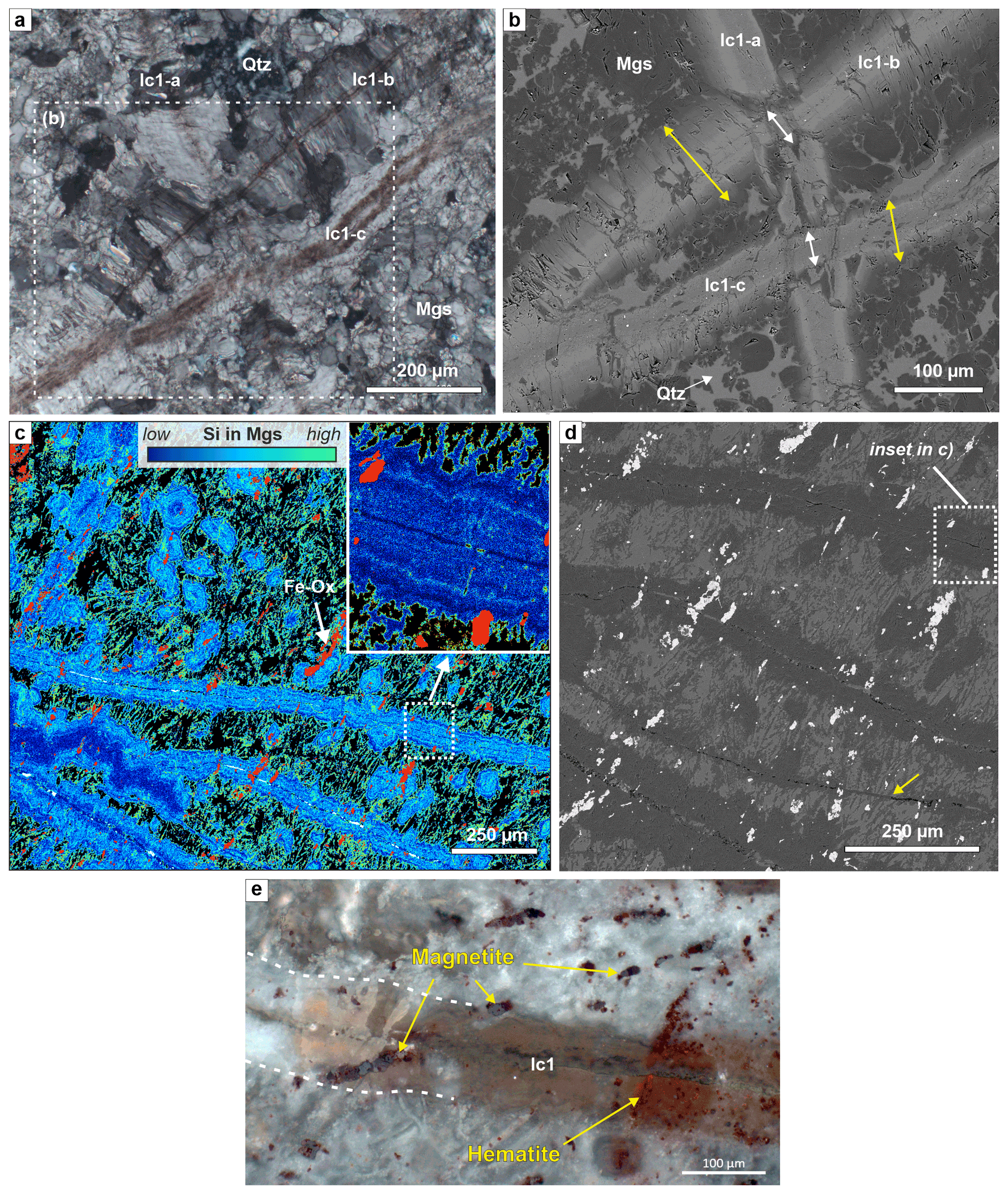
Figure 8Microstructures showing the extent of opening versus host-rock replacement by zoned magnesite veins. (a) Different generations of zoned magnesite veins with a brown, Fe-enriched median zone, showing fibrous (lc1-a, lc1-b) and wide-blocky (lc1-c) habits (xpol). (b) BSE image of the area marked in (a), showing that the true vein aperture via opening at the intersection with the earlier vein lc1-a corresponds to inclusion-bearing median zones only (white arrows), while fibrous to euhedral overgrowths indicate that a significant fraction of the total vein thickness (yellow arrows) must have formed due to replacement of the host rock (BT1B_14-1_7-11). (c) Si content in magnesite from EDX mapping (with Fe oxides in red; quartz – black; minor dolomite – white), showing vein-parallel zoning in carbonate veins and concentric zoning in matrix magnesite ellipsoids. Only the median zone of veins cuts the oblique Fe oxides. Local folding of an Si-poor vein core in the lower left. (b) BSE image of part of the area in (c); the yellow arrow marks a thin vein that did not develop the common replacement rim. (e) Crossed polarized, reflected light image of the relationship between a wide-blocky zoned magnesite vein (lc-1), magnetite, and hematite. (c, d, e) BT1B_21-3_35-40.
4.2.3 Magnesite and magnesite–dolomite veins
Magnesite veins (lc2) and magnesite–dolomite veins (lc3) cut zoned lc1 carbonate veins (Table 2; Fig. 6g). They are far less abundant than lc1 veins and commonly have irregular shapes and boundaries. Lc2 veins are composed of dull or non-luminescent magnesite with comparatively little Fe contents and without chemical zoning. They commonly have cross-fiber to blocky syntaxial textures. Lc3 carbonate veins are composed of polycrystalline magnesite with minor dolomite. Magnesite in lc3 veins may show bright pink luminescence colors under optical CL, likely due to enrichment in Mn contents, similar to sc3 veins in serpentinite (see Table 1).
4.2.4 Cryptic quartz veins
Cryptic quartz veins are one of the earliest quartz generations in listvenite (lq1, Table 2). They are usually indistinguishable from matrix quartz grains in plane- and cross-polarized light but become visible by CL due to their dull luminescence compared to brighter matrix quartz (Fig. 9a, b). Cryptic quartz veins commonly have a vermicular, highly irregular, and discontinuous geometry. Many show several stages of growth as revealed by cross-cutting or reactivated zones of different luminescence (Fig. 9b). Locally, CL reveals the presence of a thin, dark luminescent zone (<10 µm) with constant thickness over short length scales that could indicate a median zone or refracturing. Notably, most of these veins do not cut zoned magnesite ellipsoids of the listvenite matrix. Instead, they have highly variable thickness and deflect around magnesite ellipsoids. The cryptic quartz veins usually abut against zoned magnesite veins or exploit their wall–host rock interface. The abundance of this vein type is difficult to estimate due their cryptic nature and because matrix quartz in places shows a similarly dull luminescence, but overall they are less abundant and younger than zoned magnesite veins.
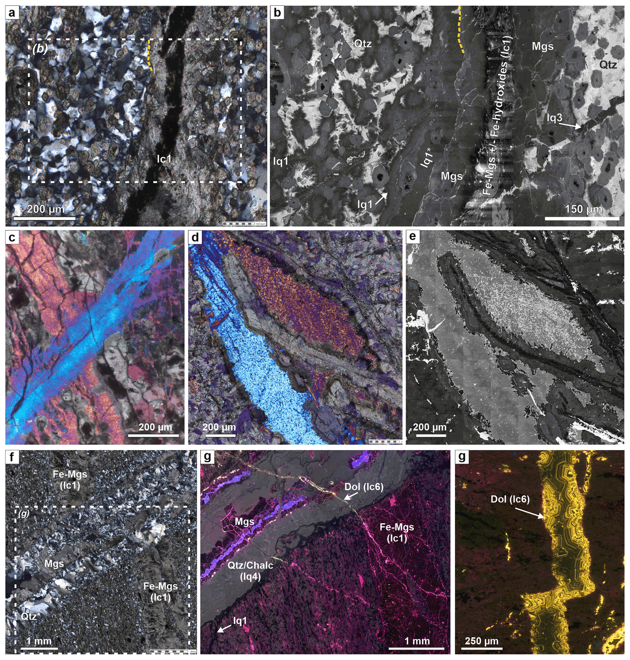
Figure 9Quartz and late dolomite veins in listvenite. (a) Crossed polarized micrograph of a cryptic quartz vein adjacent to a zoned magnesite vein (lc1). (b) SEM-CL image of the marked area in (a), showing two generations of dark luminescent cryptic quartz veins (lq1 and lq1*) in bright luminescent matrix quartz and exploiting the zoned magnesite vein interface. Cryptic quartz veins do not cut magnesite ellipsoids in the matrix. A later quartz vein (lq3) cuts both magnesite ellipsoids and the zoned magnesite vein. (c) Two cross-cutting generations of microcrystalline quartz veins with distinct crystal preferred orientations (xpol with 1λ plate). (d, e) Cross-cutting relationship between zoned magnesite veins and microcrystalline quartz (d: ViP xpol with 1λ plate; e: SEM-CL); dendritic magnesite overgrowths on the carbonate vein are undisturbed by the microcrystalline quartz. (f, g) Crossed polarized micrograph and optical CL mosaic image of a quartz–magnesite vein (lq4), with chalcedony cutting a zoned magnesite vein. Magnesite in the vein has luminescence distinct from that in the listvenite matrix. A late, thin dolomite vein cuts all other vein generations. (g) Optical CL mosaic image of a late syntaxial lc6 dolomite vein in listvenite, showing dull to bright yellow oscillatory growth zoning into an open fracture. The vein is roughly oriented vertical (parallel with respect to the core orientation) (a, b, f, g: sample BT1B_14-3_77-80, see marked areas in Fig. 7a, c: BT1B_56-4_45-50; e, f: BT1B_67-2_36-40; g: BT1B_32-1_17-19.)
4.2.5 Microcrystalline quartz veins
The most enigmatic vein type in listvenites of Hole BT1B is microcrystalline quartz veins (Fig. 9c–e; lq2, Table 2). They consist of microcrystalline, equigranular quartz with a strong crystallographic preferred orientation over long distances, with small variations of the preferred orientation locally producing striped or chessboard patterns under crossed polarized light. Similar microcrystalline quartz occurs as variably sized patches in the listvenite matrix, suggesting that it may be a replacement microstructure instead of a classic vein infill. SEM-CL imaging shows that the microcrystalline quartz is composed of spheroidal to equant, dull luminescent quartz grains (3–8 µm) surrounded by fibrous, bright luminescent SiO2 matrix. Magnesite spheroids are not cut by these veins but in places occur within them. Inner parts of zoned magnesite veins appear to cut microcrystalline quartz veins and patches. However, botryoidal, euhedral, and dendritic carbonate vein rims are undisturbed by the microcrystalline quartz (Fig. 9d, e), suggesting that at least some of the microcrystalline quartz formed after zoned magnesite veins.
4.2.6 Quartz–magnesite and quartz–dolomite veins
Bimineralic quartz–magnesite as well as quartz–dolomite veins (lq4 and lc4 in Table 2) cut earlier quartz and carbonate veins (Fig. 9c, d). These veins are mostly syntaxial, with sharp, straight vein walls and abundant host-rock inclusions. Wide-blocky carbonate and quartz can be present in the vein center, while crystals at the vein walls are smaller, show growth competition textures, and commonly have euhedral terminations towards the vein center. Irregular domains of radial chalcedony growth are common, in places also nucleating on the wide-blocky carbonate and quartz crystals along the vein center (Fig. S8 in the Supplement). Cross-cutting relationships indicate that these veins cut listvenite host rock and are thus younger than carbonation of serpentinite. They are usually older than cataclasites (although in some cases also younger than cataclasis) and are cut by late, open or brecciated carbonate veins (Menzel et al., 2020).
4.2.7 Late carbonate veins
The youngest vein generations in BT1 listvenites are mono-mineralic magnesite (lc5) and dolomite (lc6) veins (Table 2). They have variable microstructures with mostly syntaxial to blocky habits, common euhedral crystal facets, and in places open porosity. CL imaging reveals highly oscillatory growth zoning in dolomite within some of these veins (Fig. 9g), which may be due to cyclic variations in Mn incorporation during precipitation, a common phenomenon in calcite veins elsewhere (e.g., Wang and Merino, 1992).
5.1 Sequence of reactions and vein formation
Vein microstructures in carbonated peridotites are key to understanding the coupled feedbacks between deformation, fluid flow, and carbonation, and they may provide valuable insights for industrial carbon storage by mineral carbonation (van Noort et al., 2013). In the BT1B listvenites and serpentinites, vein-fill minerals may have formed due to (i) precipitation from supersaturated fluids along fluid pathways in serpentinite during an incipient stage of carbonation, (ii) precipitation of the reaction products magnesite and/or quartz during in situ dissolution and replacement of the host serpentine, and (iii) precipitation along fractures in listvenite after termination of the actual carbonation reaction. Microstructural evidence and cross-cutting relationships presented in this study indicate that pseudomorphic veins, zoned magnesite veins, and cryptic and microcrystalline quartz veins are coeval with different stages of the carbonation reaction sequence that consumes serpentine (Fig. 10). Some of the textures and cross-cutting relationships are ambiguous, but in general terms a first stage of carbonate veining preceded extensive crystallization of quartz in veins and the listvenite matrix. Therefore, syn-carbonation veining must have occurred in the early upper Cretaceous coinciding with the main timing of listvenite formation (Falk and Kelemen, 2015). We distinguish the following stages of microstructural evolution.
- I.
Early, high-temperature (T>700 ∘C) deformation of the banded peridotite protolith, producing a fabric with elongated and aligned Cr spinel and orthopyroxene. The protolith was partly refertilized through high-T metasomatism (Godard et al., 2021) that is typical of the basal peridotites in the Samail ophiolite (Prigent et al., 2018).
- II.
Serpentinization of olivine and pyroxene to form mesh and bastite serpentine, respectively, likely at T<250 ∘C with formation of magnetite and, in dunitic protolith compositions, brucite. Deformation after and possibly also during serpentinization caused ductile shear zones with aligned lizardite and flattened magnetite mesh structures (Menzel et al., 2022). In places, serpentinization may have been accompanied by cataclasis, similar to that in partially serpentinized peridotite of the Wadi Tayin massif (Aupart et al., 2021).
- III.
Formation of (not mesh) serpentine–magnetite and banded serpentine crack–seal veins (ss1, ss2; Table 1). Cleavage-parallel serpentine veins formed in foliated serpentinites (Fig. 2d), although they may be obscured by carbonate in BT1B.
- IV.
Incipient precipitation of carbonate, in particular Fe-rich magnesite, as ellipsoidal to spheroidal grains in the serpentine matrix (Beinlich et al., 2020b), along the outlines of polygonal mesh cells (sc0 in Figs. 2, 10) and in early carbonate veins (sc1 and the median zone of sc2 veins; Table 1). The ellipsoidal–spheroidal grain habit is interpreted to be a result of disequilibrium precipitation at high oversaturation (Beinlich et al., 2020b) and/or under deviatoric stress (Menzel et al., 2022). Remnant olivine, pyroxene, and brucite after serpentinization may have reacted preferentially with CO2 to form carbonate.
- V.
Local (about 10 %–15 % of core BT1B) ductile deformation of the reacting, serpentine-bearing assemblage, leading to folding of early carbonate veins and development of a penetrative foliation by oriented growth of ellipsoidal magnesite in the matrix (Menzel et al., 2022).
- VI.
Concentric growth of matrix magnesite grains and widening of zoned magnesite veins by replacement of the serpentine matrix and/or opening, in places with precipitation of some talc or quartz (Fig. 4). This is consistent with the microstructures of overgrowths on folded magnesite veins in ductily deformed listvenites from Hole BT1B, which indicate that carbonate vein opening and deformation occurred before listvenite formation was completed (Menzel et al., 2022). This stage may have been accompanied by silica loss on a local scale.
- VII.
Incipient precipitation of quartz in the remaining serpentine matrix and formation of early, syn-carbonation quartz veins (sq1 in Table 1; lq1 and lq2 in Table 2). In places, opal may have precipitated initially and later recrystallized to quartz or chalcedony (Kelemen et al., 2022).
- VIII.
Dendritic growth of magnesite on ellipsoidal matrix grains and along the walls of early carbonate veins (Figs. 7; 9e) as well as precipitation of cryptic and/or microcrystalline quartz in veins and the matrix. Complete replacement of remnant matrix serpentine by quartz and minor carbonate concluded the carbonation reaction.
- IX.
Syntaxial to blocky quartz–carbonate veins that cut listvenite and, rarely, serpentinite (lq4, lc4; Figs. 9f, g; 10). Quartz proportions in these veins are typically higher than carbonate, pointing to silica influx or redistribution during this stage. It is possible that the formation of bimineralic quartz–carbonate veins (lq4, lc4) occurred in listvenite, while carbonation proceeded at the advancing reaction front along the serpentinite–listvenite contact. Alternatively, they may have formed due to fracturing during a first deformational overprint following carbonation.
- X.
Cataclasis, sharp faults, and late carbonate veins overprinting listvenite and serpentinite (Fig. 10; sc4, lc5, lc6 in Tables 1 and 2), in parts related to local Ca gain and Mg loss in listvenite (Menzel et al., 2020).
In terms of chemical reactions, we infer that the main stages of progressive transformation to listvenite proceeded by the following simplified reactions.
-
Hydration of olivine and orthopyroxene to serpentine and brucite, forming serpentine mesh veins and bastite (stage II), with brucite proportions depending on orthopyroxene abundance (for ):
-
Incipient magnesite formation in the matrix, sc0 veins, and the center of sc1 and sc2 veins (stage IV–VI) by reaction of brucite and serpentine with CO2, initially likely with little formation of secondary silicates but related to transfer of aqueous silica (SiO2(aq); for 0 ≤ n ≤ 2):
Isochemical replacement of serpentine by magnesite and quartz (n=0 in Reaction R3) would lead to a magnesite quartz proportion of 1.5 molar, equivalent to ∼ 34 vol % quartz. Local mobility of aqueous silica is inferred from the observation that many matrix domains and magnesite veins have magnesite quartz proportions significantly higher than 1.5 molar (Figs. 3; 4). Thus, only some of the released silica precipitated in situ, forming SiO2 inclusions in magnesite or, rarely, talc (e.g., Fig. 4), indicating local leaching of SiO2(aq). In addition or alternatively to silica loss, Reaction (R3) may be complemented by influx of aqueous Mg-bearing species and local Ca mobility where early dolomite is present (see Beinlich et al., 2020b).
-
Reaction of serpentine with CO2 to form magnesite and quartz (stages VII–VIII), locally with excess influx of aqueous silica derived from Reaction (R3), forming syn-carbonation quartz veins and (microcrystalline) quartz-rich domains:
-
Post-listvenite syntaxial and late veins in listvenite (stages IX–X) do not show replacement structures involving reaction of serpentine with CO2 but are inferred to have formed primarily by precipitation from aqueous solutions with variable concentration of dissolved Si, Ca, Mg, and bicarbonate–carbonate:
Some of the dolomite locally replacing early magnesite veins and filling late veins may be reflective of magnesite dissolution in combination with influx of Ca-bearing fluids, possibly related to fluid flow during brittle overprint (Menzel et al., 2020). Some of the youngest post-listvenite magnesite and dolomite vein generations (lc5, lc6) may have a similar origin as very young magnesite, dolomite, and calcite–aragonite veins related to interaction of Mg–HCO- and Ca–OH−-bearing groundwater with the Samail peridotite (Noël et al., 2018; Streit et al., 2012; Ternieten et al., 2021).
Because the transformation of serpentine into magnesite and quartz (Reactions R3 and R4) consumes CO2 while releasing H2O, the fluid evolves to more aqueous compositions with reaction progress. Thus, steps II–VIII and Reactions (R1)–(R4) may have occurred at the same time along different advancing reaction fronts, which correspond to the contacts between partially hydrated peridotite, serpentinite, carbonate-bearing serpentinite, and listvenite.
We note that not every stage I–X is recognizable in each core section. Moreover, field exposures around site BT1 show high variability of strongly veined domains alternating with more massive listvenite intervals. We further note that vein microstructures in dolomite and dolomite–calcite listvenites that are common further north in the Fanjah region are somewhat different from the magnesite-dominated BT1B listvenites studied here, as they are related to a massive gain of Ca through fluid influx (Reaction R5).
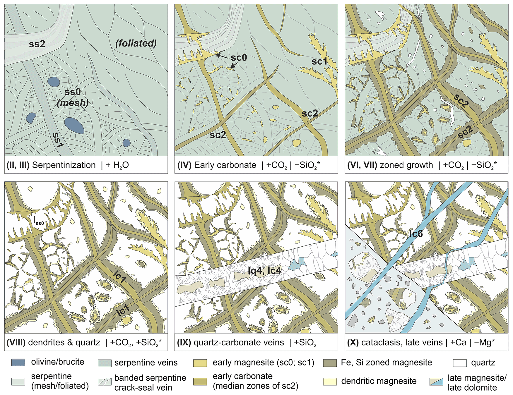
Figure 10Sketch of the evolution of carbonation and vein formation in Hole BT1B, as inferred from serpentinite and listvenite samples (different stages, see text). Different stages were related to differing element transfer with gains (denoted by, e.g., + H2O); inferred losses (e.g., −SiO2*) are likely only relevant on a local scale. For clarity, not all vein generations (see Tables 1 and 2) are shown.
5.2 Influence of pre-existing serpentine structures on veining
Pseudomorphic carbonate after mesh and crack–seal serpentine veins (Figs. 2e–h; 6a, b) demonstrate that the microstructure of the precursor serpentinite determined the location and structure of vein networks to a great extent. The local presence of brucite and/or variations in Si, Al, and Fe contents of serpentine may have caused preferential carbonation at specific microstructural sites where carbonation reaction affinity is higher. Brucite, which shows very fast carbonation reaction kinetics in low-temperature experiments (Harrison et al., 2013; Hövelmann et al., 2012), is commonly observed together with magnetite along serpentine mesh veins in serpentinites (Schwarzenbach et al., 2016). The preferential replacement of previous brucite by magnesite (Reaction R1) may thus explain the polygonal, mesh–pseudomorphic carbonate vein network in some serpentinites and listvenites of Hole BT1B (Figs. 2e–f; 6a). However, brucite is typically only abundant in serpentinized dunite because its stability requires high Mg Si of the bulk rock. As large parts of the listvenites of Hole BT1B are inferred to have had a serpentinized harzburgite and lherzolite protolith based on major and trace element geochemistry (Godard et al., 2021), we infer that brucite was only common in minor dunitic intervals. On the other hand, different parts of mesh microstructures and different veins in serpentinite can be composed of a variety of serpentine polytypes with different crystal structure. Acid-leaching experiments have shown that dissolution rates can differ greatly between these polytypes, with much higher Mg extraction rates for chrysotile, nano-tubular chrysotile, and poorly ordered lizardite compared to Al-bearing lizardite, polygonal serpentine, and antigorite (Lacinska et al., 2016). It is therefore likely that different serpentine polytypes also show variable dissolution rates during reaction with moderately acidic, CO2-bearing aqueous fluids. This may explain why specific microstructural sites are preferentially replaced by carbonate, producing pseudomorphic textures. Besides variable dissolution rates, serpentine polytypes also have different crystal habits with differing strength and surface area. Thus, we propose that the heterogeneous microstructures of different serpentine polytypes form micro-environments with different inter- and intra-granular nano-porous matrix permeability as well as micron-scale permeability along fractures. These heterogeneities create complex relationships between diffusive and advective solute transfer, fluid flow rates, and kinetics that control different levels of pseudomorphic inheritance.
Banded serpentine crack–seal veins appear to have a particularly strong impact on local fracture formation and small-scale porosity morphology. Such serpentine veins typically consist of chrysotile fibers alternating with lizardite or polygonal serpentine, recording repeated crack–seal cycles (Andreani et al., 2004; Tarling et al., 2021). Due to the high tensile strength of chrysotile parallel to fiber orientations, fracturing and associated permeability are expected to occur preferentially along the vein–host rock interface, which is what we observed in pseudomorphic replacement microstructures (Figs. 2h; 6b).
5.3 Vein growth mechanisms – opening versus replacement
Opening of dilatant fractures can increase permeability and provide pathways for fluid infiltration that would allow carbonation to proceed. What type and how much permeability is created, however, depend on how soon after opening and in which direction the vein becomes filled. When crystals precipitate at the vein walls and grow inwards towards the vein center (syntaxial veins), fluid replenishment and, potentially, crack–seal events occur along the vein center (Bons et al., 2012). This potentially results in a loss of connectivity between the vein and matrix permeability network because of mineralization along the vein–matrix interface. In contrast, if crystal growth proceeds from a median zone towards the vein walls (antitaxial veins), fluid flow is focused along the vein–host rock interface, creating a connected permeability network between the fracture and rock matrix. We found examples of both types of vein growth in the BT1B serpentinites and listvenites (Tables 1 and 2). In general terms, early serpentine and carbonate veins (e.g., Figs. 2, 4) as well as some early quartz veins (Fig. 5b) tend to show antitaxial textures, whereas younger quartz–carbonate veins (lq4, lc4; Table 2) tend to be syntaxial. If the process was entirely mechanical, this would suggest a reduction in the connectivity of the permeability network over time. Owing to chemical–mineralogical replacements that occur during carbonation, however, the mechanism is more complex during listvenite formation.
Current models of vein formation treat the host rock as a non-reactive substrate with vein formation due to precipitation from aqueous solution in fluid-filled fractures (Ankit et al., 2015; Hilgers et al., 2001; Hubert et al., 2009; Spruženiece et al., 2021a, b). This mode of vein formation is commonly observed in carbonate veins in altered oceanic crust (e.g., Quandt et al., 2020). In the case of carbonate veining during listvenite formation, however, mechanical opening was accompanied by replacement of the host serpentinite (Fig. 8) so that the morphology of the fracture wall is controlled by dissolution and replacement in addition to dilatancy. Therefore, the wall rock changes its morphology by dissolution, and vein volume is further accommodated by replacement. In addition to evidence from cross-cutting relationships and overgrown passive markers within veins and the listvenite matrix (Fig. 8), the high abundance of SiO2 nano-inclusions within zoned magnesite veins in listvenite of Hole BT1 as confirmed by transmission electron microscope (TEM) (Beinlich et al., 2020b; Menzel et al., 2022) indicates that silica saturation and quartz nucleation rate were high during carbonate vein growth, which provides further evidence for simultaneous serpentine dissolution.
Microstructures indicative of growth zoning during carbonate vein growth from a median zone outward into the serpentine matrix (Fig. 7d) suggest that there was a reactive fluid film and significant permeability along the vein–host rock interface (Fig. 11). Compared to the fracture permeability created initially by dilatant opening of the vein, which may easily clog if mineral precipitation is fast, we postulate that this interface permeability was maintained by vein growth by replacement and coupled dissolution of serpentine. Facetted carbonate crystal terminations, partial talc infills, and secondary exploitation by quartz veins (Fig. 4) suggest that the vein–serpentinite interface was a preferential site of focused, advective fluid flow and, in places, new fracture formation. This interface permeability thus promoted continued vein growth by serpentine dissolution, in addition to supplying CO2-bearing fluid to the nano-porous matrix of the non-veined host serpentine through diffusive solute transfer, facilitating progressive carbonation of serpentinite. Subsequent syntaxial quartz–carbonate veins most likely lacked such a reaction front, with fluid pathways concentrated along the center of the vein.
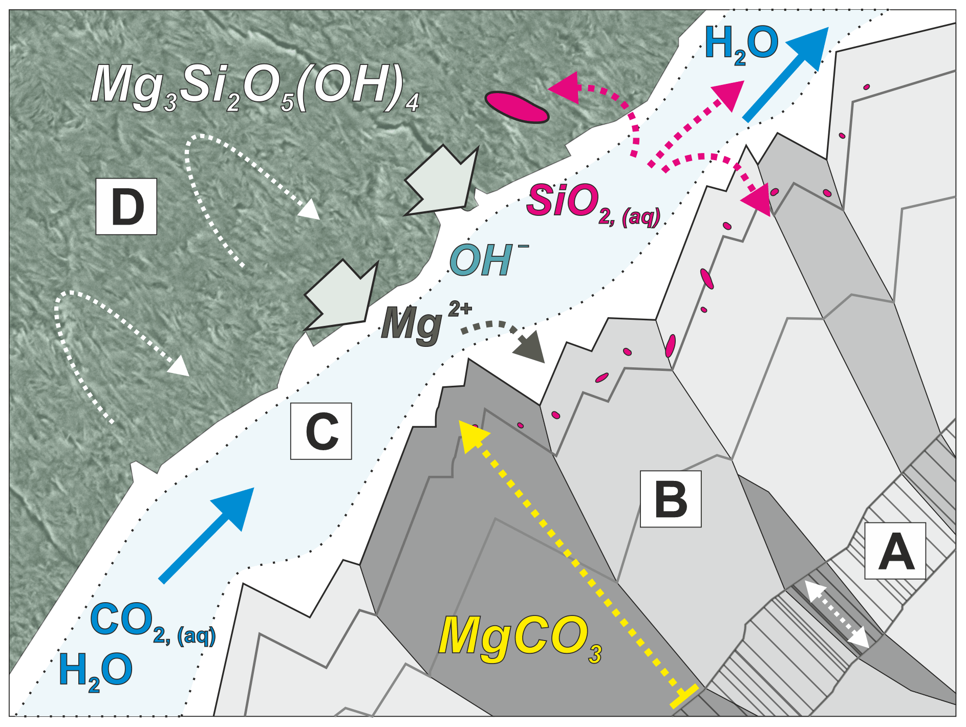
Figure 11Conceptual sketch of magnesite vein growth by replacement of serpentine. Domain A: initial dilatant fracture with carbonate infill, forming the median lines of zoned magnesite veins. B: magnesite vein growth rim formed by replacement. C: interface permeability at vein walls causes development of a fluid film with diffusion-dominated boundary layers (white) and a central advective flow zone (light blue), which allows CO2 influx and drives coupled serpentine dissolution and carbonate precipitation. The widths of boundary layers relative to the advective zone depend on fluid flow rate. The overall width of domain C is highly exaggerated for illustration purposes. D: nano-porous serpentine with predominantly diffusive solute transfer in matrix permeability. The observations show that only small fractions of dissolved silica precipitate in situ (red), forming nano-inclusions in magnesite; most silica is leached and precipitates in other micro-environments.
5.4 Formation of closely spaced carbonate vein sets
Because early, zoned magnesite veins are extremely abundant in serpentinite and listvenite of Hole BT1B and because of their likely role in acting as main fluid pathways early in the carbonation process, understanding their formation mechanism is integral to deciphering the factors controlling carbonation reaction progress. A key feature of these carbonate veins is that they commonly form closely spaced, subparallel sets. Similar, subparallel serpentine vein sets occur in serpentinites in the vicinity of listvenites in the area (Fig. 2b) and are common in other serpentinized peridotites of the Samail ophiolite (Kelemen et al., 2020a, c). Parallel, closely spaced serpentine vein sets are also known from oceanic peridotites (Andreani et al., 2007). Repeated fracturing parallel to existing veins requires the veins and the vein–host rock interface to be stronger than the host rock (Virgo et al., 2014). However, the reaction front at the vein – serpentinite interface of zoned magnesite veins (sc2 and lc1 veins; Fig. 11) speaks against a strong vein–host rock interface during this stage of reaction. Furthermore, the zoning patterns, documenting changing fluid compositions and/or redox conditions, are consistent within different veins of the same set. Hence, a sequential process of repeated parallel fracturing and sealing by zoned carbonate growth is unlikely because it would require similar cyclic variations of fluid composition and redox conditions to be repeated for each vein.
A more feasible explanation is that the zoned parts of the carbonate veins formed along a pre-existing fracture or vein set. If the vein material had a higher strength than the host serpentinite, closely spaced vein sets may form. This may have happened if the initial vein fill had a higher permeability or higher carbonation reaction affinity than serpentine of the host rock, so that the veins preferentially became replaced by carbonate. Zoned carbonate growth may then have proceeded from the narrow vein set into the serpentine matrix in a later step. A precursor vein fill of fibrous chrysotile may be a suitable candidate because chrysotile has the same or higher tensile strength compared to matrix serpentine, facilitating fracturing parallel to existing veins. Chrysotile veins may also show higher carbonation reaction rates than lizardite due to the larger surface area of fibrous aggregates, especially if they have a nano-tubular crystal morphology (Lacinska et al., 2016), in line with the observation of other pseudomorphic carbonate veins (Fig. 2c, h). High-resolution SEM imaging of a broad-ion-beam polished sample of veined serpentinite (see methods) reveals that fibrous serpentine veins can have substantially higher micro- to nano-porosity than the matrix serpentine (Fig. 12), confirming that they may be sites of preferential reactive fluid flux. Similar subparallel serpentine vein sets may thus have been the precursor of the closely spaced sc2 and lc1 carbonate veins. Such serpentine veins may form by repeated fracturing of serpentinite or during serpentinization of olivine when tectonic stress enhances widening of favorable orientations of mesh veins (see Fig. 5 of Aupart et al., 2021).
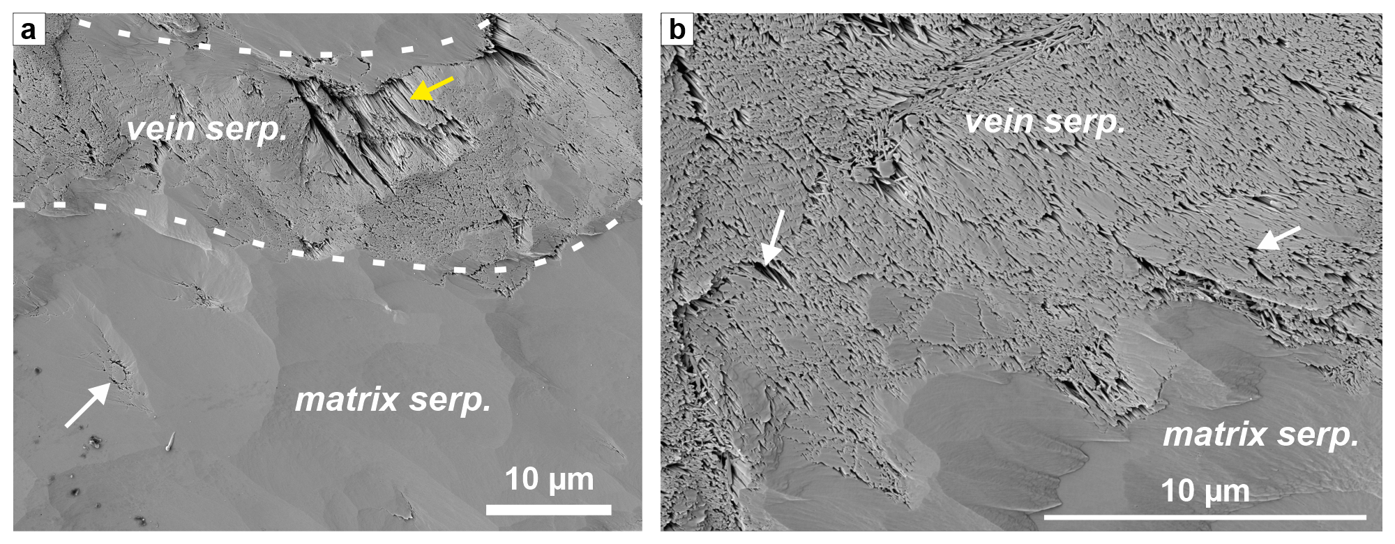
Figure 12SE image of a broad-ion-beam polished serpentine vein in foliated serpentinite (a) with a close-up of the vein–wall rock interface (b), showing that the vein serpentine is highly (nano-)porous in comparison to matrix serpentine. White arrows indicate examples of nano-porosity (black). In the vein, porosity is controlled by fibrous serpentine as seen in the poorly polished area (yellow arrow in a). The vein domain corresponds to the blue bands in Fig. 2d (sample OM20-13).
5.5 Reaction-induced fracturing?
Listvenites are inferred to form, among other settings, at the base of ophiolites or in the shallow mantle wedge of subduction zones (e.g., Kelemen and Manning, 2015). At these conditions, all principal stresses will be compressive. Thus, fracturing by tensile or shear failure typically requires a reduction of effective stress by fluid overpressure (Hilgers et al., 2006; Sibson, 2017). Experiments and numerical models of volume-expanding hydration reactions have shown that crystallization pressure may locally create gradients in differential stress, which can also facilitate fracture formation, increasing permeability and reactive surface area (Malthe-Sørenssen et al., 2006; Rudge et al., 2010; Shimizu and Okamoto, 2016). In combination with elevated fluid pressure, these local stress gradients caused by “force of crystallization” could lead to dilatant opening and propagation of existing veins, formation of new fractures, or enhanced pressure solution of the rock matrix (Fletcher and Merino, 2001). Kelemen and Hirth (2012) propose that crystallization pressure during peridotite carbonation can be large enough to exceed the stress required for frictional failure, creating a positive feedback for reaction progress via fracturing. This process has been shown to be efficient for reactions wherein volume changes are very large, such as during hydration of periclase (MgO) to brucite (Zheng et al., 2019, 2018), and important during serpentinization of olivine (Evans et al., 2020; Plümper et al., 2012; Yoshida et al., 2020). However, the extent to which crystallization pressure influences listvenite formation is less certain (van Noort et al., 2017). Full hydration and carbonation of olivine increase the solid volume by 33 % and >40 % (Kelemen et al., 2011), respectively, while the conversion of serpentine to magnesite and quartz is predicted to cause a solid volume expansion of 18 %–22 % (Hansen et al., 2005; Kelemen et al., 2022). Reaction-induced fracturing due to crystallization pressure and volume expansion may thus have occurred at the advancing serpentinization and carbonation reaction fronts that formed the serpentinites and listvenites at site BT1.
Zoned magnesite veins may theoretically have opened through crystallization pressure to some extent because, unlike in syntaxial veins, carbonate growth occurred from the center outwards. However, several observations argue against this mechanism dominating during early carbonation: (i) passive markers show that much of the vein width was accommodated by replacement rather than opening (Fig. 8), (ii) euhedral growth patterns point to the presence of an open fluid conduit at the vein–matrix interface (Fig. 11), and (iii) most zoned magnesite veins in serpentinites and listvenites contain a much smaller proportion of SiO2 (mostly as inclusions in magnesite) than expected for isochemical replacement of serpentine (Figs. 4, 7, 8), indicating that silica was leached (Reaction R3). Mg isotope geochemistry and bulk chemistry mass balance calculations suggest that Mg in listvenite magnesite is derived from local dissolution of the peridotite protolith (de Obeso et al., 2021; Godard et al., 2021). Assuming that external Mg influx was negligible and that magnesite growth is rate-limited by serpentine dissolution, Reaction (R3) would cause volume expansion only if at least ∼ 22 vol % of the solid reaction products is quartz. If more SiO2(aq) is leached than precipitated in situ as quartz (n>1 in Reaction R3), solid volume change would be negative. Since in situ quartz abundance in zoned magnesite veins is typically <10 vol %, combined influx of CO2 and local leaching of silica probably resulted in a solid volume decrease at the vein–serpentine interface because magnesite has a higher density than serpentine. The leached silica may have precipitated synchronously in different microstructural sites in the rock matrix, forming quartz-rich domains, or as cryptic, microcrystalline, or syntaxial quartz veins (Fig. 8; Reaction R4) further downstream along the reaction front or in listvenite. Abundant SiO2 nano-inclusions in magnesite point to widespread quartz oversaturation and high nucleation rates. This suggests a non-trivial coupling between the surface properties, porosity, and dissolution rate of serpentine and the interface geometry, solute transport, and precipitation kinetics during vein growth. Possibly, some local silica mobilization occurred in the form of suspended silica nano-aggregates at high fluid flow rates. The occurrence of centimeter-scale bulk chemical variations in the BT1B listvenites suggests that similar local mass transfer was commonplace during listvenite formation (Godard et al., 2021).
Numerical models suggest that volume-increasing reactions with fast reaction kinetics induce polygonal and hierarchical fracture patterns (e.g., Okamoto and Shimizu, 2015; Ulven et al., 2014), in agreement with the typical mesh textures in serpentinites. In contrast, the BT1B zoned magnesite vein sets have parallel or anastomosing patterns that indicate a strong influence of tectonic stress during initial fracture formation.
Taken together, these observations suggest that although volume expansion associated with the overall transformation to listvenite (combined Reactions R3 and R4) caused some crystallization pressure, zoned magnesite veins did not primarily grow through force of crystallization. Crystallization pressure may have contributed to the external stress responsible for the initial, dilatant fractures along which the carbonate veins developed. A similar conclusion can be drawn from the microstructures of pseudomorphic carbonate (sc0) and feathery, cleavage-parallel carbonate veins (sc1) in carbonate-bearing serpentinite (Table 1): quartz is rare or absent in their vicinity, indicating that their formation did not require volume expansion if Mg was sourced locally from dissolving serpentine. Reaction-induced fracturing was, however, likely prevalent during the preceding highly volume-expanding serpentinization, which created mesh and vein textures with heterogeneous permeability and carbonation affinity.
5.6 Tectonic context
CO2 fluid flux derived from subduction and/or underthrusting of (meta)sediments below the Samail ophiolite is considered the most likely setting of listvenite formation at site BT1 (de Obeso et al., 2022; Kelemen et al., 2022), although carbonation during extensional reactivation of the thrust fault in an early phase after obduction is possible (see Sect. 2.2). While the common parallelism of zoned magnesite veins points to a strong influence of tectonic stress on vein formation, our results do not allow us to determine whether veining occurred in an overall contractional or extensional setting. This caveat is due to unoriented drill cores and the complexity arising from the observation that most of the syn-carbonation veins are replacement and not purely dilatant veins. Folding (Kelemen et al., 2022) and several phases of post-listvenite brittle faulting (Menzel et al., 2020) further complicate a reconstruction of paleo-stress directions during formation of the different vein generations. Based on ductile deformation microstructures, the morphology of preserved micro- and nano-pores, and the requirement for high fluid fluxes to form listvenite, Menzel et al. (2022) inferred that pore pressures were high during carbonation. High pore pressures can also lead to tensile and extensional fracturing in thrust settings, which may be particularly widespread at contacts and in mixtures of lithologies with disparate rheology (e.g., Sibson, 2017). Such conditions may be common at the reaction front along the contacts of comparatively strong listvenite lenses enclosed in weak, sheared serpentinite. In Oman, fluid overpressure cells formed in response to burial below the ophiolite and the Hawasina nappes, causing veining in (par)autochthonous carbonate rocks (Grobe et al., 2019). The widespread and multiphase syn-carbonation veining observed in the BT1B serpentinites and carbonates may thus be a combined effect of reaction-induced stress from serpentinization and cyclic fluctuations between sub-lithostatic and lithostatic fluid pressures in the deforming and reacting basal peridotites during subduction and/or ophiolite emplacement. With subsequent progressive cooling of the ophiolite and underlying units, CO2 concentration in infiltrating fluids likely decreased. Thus, the fluid chemistry may have switched to more Ca and/or Mg bicarbonate ionic solutions favoring the formation of syntaxial, post-listvenite veins and precipitation of carbonate vein fill in contrast to the earlier syn-listvenite replacement veins that formed by reaction of serpentine with CO2.
Microstructures and cross-cutting relationships in serpentinites and listvenites of Hole BT1B demonstrate that several vein generations formed during carbonation reactions. These veins constitute large volumes of the BT1B listvenites, showing that fracturing and related advective fluid flow were integral to carbonation progress. The incipient stages of carbonation are consistently related to pseudomorphic carbonate and zoned magnesite veins. Zoning of Ca, Fe, and Si contents in early carbonate veins records variations in fluid composition, changes in redox conditions, and variations of supersaturation and nucleation rates of silica during progressive serpentine replacement. Cross-cutting relations and passive markers indicate that zoned magnesite veins formed as incipient dilatant, often parallel, and closely spaced microfractures, possibly initially filled with precursor chrysotile that was preferentially replaced by carbonate. From this incipient median zone, a permeable micro-reaction front developed into the serpentine matrix upon further CO2 influx, allowing vein growth to continue through a dilatant–reactive process. These observations indicate that vein–wall rock interfaces served as essential fluid conduits during transformation of the non-veined matrix into listvenite. Sets of parallel to anastomosing carbonate veins point to an important role of tectonic stress during early carbonation, likely complemented by deviatoric stress generated by volume expansion at the serpentinization front advancing ahead of the carbonation reaction front, whereas crystallization pressure from magnesite precipitation was most likely less significant during veining. As carbonation progressed, permeability was probably reduced during subsequent quartz veining and further silica replacement of the matrix, but a lack of remnant serpentinite in listvenite horizons indicates that penetration of CO2-rich fluid through the vein and matrix permeability network was sufficient for carbonation to proceed to completion. Our results suggest that in this natural example, veining caused by tectonic stress and fluid overpressure is an important mechanism to create permeability despite carbonate precipitation. Without the added effect of tectonic deformation and related deviatoric stress, it is possible that permeability created through reaction-driven fracturing ± replacement veining alone is not enough to allow for the necessary fluid flux for carbonation to progress. Therefore, the extent of carbon mineralization and permanent CO2 sequestration that can be attained via experimental in situ CO2 injection might be limited.
Archive halves and samples of core BT1B are available through the Oman Drilling Project (https://www.omandrilling.ac.uk/samples-data, Oman Drilling Project, 2022). Digitized thin sections of some of the samples used in this study are available for download as a Supplement of the Oman Drilling Project (http://publications.iodp.org/other/Oman/SUPP_MAT/index.html#SUPP_MAT_Z, International Ocean Discovery Program Publications, 2022).
All main data are contained in the figures and tables of the paper and the Supplement; raw images of figures are available from the authors upon request.
The supplement related to this article is available online at: https://doi.org/10.5194/se-13-1191-2022-supplement.
MDM and JLU designed the study, conducted fieldwork, and studied the microstructures and petrography; MDM and TD refined the vein classification; MDM performed SEM imaging, EDX mapping, optical CL analysis, and image processing, as well as drafting the figures; EU conducted SEM and SEM-CL analysis. All authors discussed and interpreted the results. MDM led writing and revision of the paper, to which all authors contributed.
The contact author has declared that none of the authors has any competing interests.
Publisher's note: Copernicus Publications remains neutral with regard to jurisdictional claims in published maps and institutional affiliations.
We would like to thank Michael Kettermann and Yumiko Harigane for sampling onboard Chikyu and Peter Kelemen for providing an invaluable set of additional thin sections. Werner Kraus and Jonatan Schmidt are thanked for thin section preparation and technical assistance, and Sara Elliott is thanked for assistance with SEM-CL imaging and post-processing. We are grateful to the Oman Public Authority of Mining for support to conduct fieldwork and sample export. This study has benefitted from fruitful and inspiring discussions with Peter Kelemen, Romain Lafay, Juan Carlos de Obeso, Craig Manning, and others over the past years. We further acknowledge the constructive reviews by Dennis Quandt, an anonymous referee, and the topical editor Virginia Toy, whose comments helped to improve several aspects of the paper.
This research used samples and data provided by the Oman Drilling Project. The Oman Drilling Project (OmanDP) has been possible through co-mingled funds from the International Continental Scientific Drilling Project (ICDP), the Sloan Foundation – Deep Carbon Observatory (grant 2014-3-01), the US National Science Foundation (NSF-EAR-1516300), NASA – Astrobiology Institute NNA15BB02A), the German Research Foundation (DFG: KO 1723/21-1), the Japanese Society for the Promotion of Science (JSPS no. 16H06347; and KAKENHI 16H02742), the European Research Council (Adv: no. 669972), the Swiss National Science Foundation (SNF:20FI21_163073), the Japanese Marine Science and Technology Center (JAMSTEC), the International Ocean Discovery Program (IODP), and contributions from the Sultanate of Oman Ministry of Regional Municipalities and Water Resources, the Oman Public Authority of Mining, Sultan Qaboos University, CRNS-Univ. Montpellier II, Columbia University of New York, and the University of Southampton.
Manuel D. Menzel and Janos L. Urai were funded by the German Research Foundation (DFG grants UR 64/20-1, UR 64/17-1).
This paper was edited by Federico Rossetti and reviewed by Dennis Quandt and one anonymous referee.
Agard, P., Searle, M. P., Alsop, G. I., and Dubacq, B.: Crustal stacking and expulsion tectonics during continental subduction: P-T deformation constraints from Oman, Tectonics, 29, TC5018, https://doi.org/10.1029/2010TC002669, 2010.
Andreani, M., Baronnet, A., Boullier, A.-M., and Gratier, J.-P.: A microstructural study of a “crack-seal” type serpentine vein using SEM and TEM techniques, Eur. J. Mineral., 16, 585–595, 2004.
Andreani, M., Mével, C., Boullier, A. M., and Escartín, J.: Dynamic control on serpentine crystallization in veins: Constraints on hydration processes in oceanic peridotites, Geochem. Geophy. Geosy., 8, Q02012, https://doi.org/10.1029/2006GC001373, 2007.
Ankit, K., Urai, J. L., and Nestler, B.: Microstructural evolution in bitaxial crack-seal veins: A phase-field study, J. Geophys. Res.-Sol. Ea., 120, 3096–3118, 2015.
Ash, C. H. and Arksey, R. L.: The Atlin ultramafic allochthon: ophiolitic basement within the Cache Creek terrane; tectonic and metallogenic significance, 104N/12, Geological Fieldwork 1989, 1990–1, British Columbia Ministry of Energy, Mines and Petroleum Resources Victoria, BCGS_P1990-01-41_Ash, 365–374, 1989.
Aupart, C., Morales, L., Godard, M., and Jamtveit, B.: Seismic faults triggered early stage serpentinization of peridotites from the Samail Ophiolite, Oman, Earth Planet. Sc. Lett., 574, 117137, https://doi.org/10.1016/j.epsl.2021.117137, 2021.
Beinlich, A., Plümper, O., Hövelmann, J., Austrheim, H., and Jamtveit, B.: Massive serpentinite carbonation at Linnajavri, N–Norway, Terra Nova, 24, 446–455, 2012.
Beinlich, A., John, T., Vrijmoed, J. C., Tominaga, M., Magna, T., and Podladchikov, Y. Y.: Instantaneous rock transformations in the deep crust driven by reactive fluid flow, Nat. Geosci., 13, 307–311, https://doi.org/10.1038/s41561-020-0554-9, 2020a.
Beinlich, A., Plumper, O., Boter, E., Muller, I. A., Kourim, F., Ziegler, M., Harigane, Y., Lafay, R., Kelemen, P. B., and Oman Drilling Project Science Team: Ultramafic Rock Carbonation: Constraints From Listvenite Core BT1B, Oman Drilling Project, J. Geophys. Res.-Sol. Ea., 125, e2019JB019060, https://doi.org/10.1029/2019JB019060, 2020b.
Belogub, E. V., Melekestseva, I. Y., Novoselov, K. A., Zabotina, M. V., Tret'yakov, G. A., Zaykov, V. V., and Yuminov, A. M.: Listvenite-related gold deposits of the South Urals (Russia): A review, Ore Geol. Rev., 85, 247–270, 2017.
Bons, P. D., Elburg, M. A., and Gomez-Rivas, E.: A review of the formation of tectonic veins and their microstructures, J. Struct. Geol., 43, 33–62, 2012.
Boskabadi, A., Pitcairn, I. K., Leybourne, M. I., Teagle, D. A. H., Cooper, M. J., Hadizadeh, H., Nasiri Bezenjani, R., and Monazzami Bagherzadeh, R.: Carbonation of ophiolitic ultramafic rocks: Listvenite formation in the Late Cretaceous ophiolites of eastern Iran, Lithos, 352–353, 105307, https://doi.org/10.1016/j.lithos.2019.105307, 2020.
Boudier, F. and Coleman, R. G.: Cross section through the peridotite in the Samail Ophiolite, southeastern Oman Mountains, J. Geophys. Res.-Sol. Ea., 86, 2573–2592, 1981.
Chavagnac, V., Monnin, C., Ceuleneer, G., Boulart, C., and Hoareau, G.: Characterization of hyperalkaline fluids produced by low-temperature serpentinization of mantle peridotites in the Oman and Ligurian ophiolites, Geochem. Geophy. Geosy., 14, 2496–2522, 2013.
Coleman, R. G.: Tectonic setting for ophiolite obduction in Oman, J. Geophys. Res.-Sol. Ea., 86, 2497–2508, 1981.
de Obeso, J. C., Santiago Ramos, D. P., Higgins, J. A., and Kelemen, P. B.: A Mg Isotopic Perspective on the Mobility of Magnesium During Serpentinization and Carbonation of the Oman Ophiolite, J. Geophys. Res.-Sol. Ea., 126, e2020JB020237, https://doi.org/10.1029/2020JB020237, 2021.
de Obeso, J. C., Kelemen, P. B., Leong, J. M., Menzel, M. D., Manning, C. E., Godard, M., Cai, Y., Bolge, L., and Oman Drilling Project Phase 1 Science, P.: Deep Sourced Fluids for Peridotite Carbonation in the Shallow Mantle Wedge of a Fossil Subduction Zone: Sr and C Isotope Profiles of OmanDP Hole BT1B, J. Geophys. Res.-Sol. Ea., 127, e2021JB022704, https://doi.org/10.1029/2021JB022704, 2022.
Emam, A. and Zoheir, B.: Au and Cr mobilization through metasomatism: Microchemical evidence from ore-bearing listvenite, South Eastern Desert of Egypt, J. Geochem. Explor., 125, 34–45, 2013.
Evans, O., Spiegelman, M., and Kelemen, P. B.: Phase-Field Modeling of Reaction-Driven Cracking: Determining Conditions for Extensive Olivine Serpentinization, J. Geophys. Res.-Sol. Ea., 125, e2019JB018614, https://doi.org/10.1029/2019JB018614, 2020.
Falk, E. S. and Kelemen, P. B.: Geochemistry and petrology of listvenite in the Samail ophiolite, Sultanate of Oman: Complete carbonation of peridotite during ophiolite emplacement, Geochim. Cosmochim. Ac., 160, 70–90, 2015.
Fletcher, R. C. and Merino, E.: Mineral growth in rocks: kinetic-rheological models of replacement, vein formation, and syntectonic crystallization, Geochim. Cosmochim. Ac., 65, 3733–3748, 2001.
Fusseis, F., Regenauer-Lieb, K., Liu, J., Hough, R. M., and De Carlo, F.: Creep cavitation can establish a dynamic granular fluid pump in ductile shear zones, Nature, 459, 974–977, 2009.
Garber, J. M., Rioux, M., Kylander-Clark, A. R. C., Hacker, B. R., Vervoort, J. D., and Searle, M. P.: Petrochronology of Wadi Tayin Metamorphic Sole Metasediment, With Implications for the Thermal and Tectonic Evolution of the Samail Ophiolite (Oman/UAE), Tectonics, 39, e2020TC006135, https://doi.org/10.1029/2020TC006135, 2020.
Garber, J. M., Rioux, M., Searle, M. P., Kylander-Clark, A. R. C., Hacker, B. R., Vervoort, J. D., Warren, C. J., and Smye, A. J.: Dating continental subduction beneath the Samail Ophiolite: garnet, zircon, and rutile petrochronology of the As Sifah eclogites, NE Oman, J. Geophys. Res.-Sol. Ea., n/a, e2021JB022715, https://doi.org/10.1029/2021JB022715, 2021.
Giampouras, M., Garrido, C. J., Bach, W., Los, C., Fussmann, D., Monien, P., and García-Ruiz, J. M.: On the controls of mineral assemblages and textures in alkaline springs, Samail Ophiolite, Oman, Chem. Geol., 533, 119435, https://doi.org/10.1016/j.chemgeo.2019.119435, 2020.
Glennie, K. W., Boeuf, M. G. A., Clarke, M. W. H., Moody Stuart, M., Pilaar, W. F. H., and Reinhardt, B. M.: Geology of the Oman mountains, Verhandelingen van het Koninklink Nederlands Geologisch Mijnbouwkundig Genootschap, 31, Koninklijk Nederlands Geologisch Mijnbouwkundig Genootschap, Delft, EAN 9789001013103, 1974.
Godard, M., Carter, E. J., Decrausaz, T., Lafay, R., Bennett, E., Kourim, F., de Obeso, J. C., Michibayashi, K., Harris, M., Coggon, J. A., Teagle, D. A. H., Kelemen, P. B., and the Oman Drilling Project Phase 1 Science Party: Geochemical Profiles Across the Listvenite-Metamorphic Transition in the Basal Megathrust of the Semail Ophiolite: Results From Drilling at OmanDP Hole BT1B, J. Geophys. Res.-Sol. Ea., 126, e2021JB022733, https://doi.org/10.1029/2021JB022733, 2021.
Grobe, A., Virgo, S., von Hagke, C., Urai, J. L., and Littke, R.: Multiphase Structural Evolution of a Continental Margin During Obduction Orogeny: Insights From the Jebel Akhdar Dome, Oman Mountains, Tectonics, 37, 888–913, 2018.
Grobe, A., von Hagke, C., Littke, R., Dunkl, I., Wübbeler, F., Muchez, P., and Urai, J. L.: Tectono-thermal evolution of Oman's Mesozoic passive continental margin under the obducting Semail Ophiolite: a case study of Jebel Akhdar, Oman, Solid Earth, 10, 149–175, https://doi.org/10.5194/se-10-149-2019, 2019.
Hacker, B. R., Mosenfelder, J. L., and Gnos, E.: Rapid emplacement of the Oman ophiolite: Thermal and geochronologic constraints, Tectonics, 15, 1230–1247, 1996.
Hansen, L. D., Dipple, G. M., Gordon, T. M., and Kellett, D. A.: Carbonated serpentinite (listwanite) at Atlin, British Columbia: A geological analogue to carbon dioxide sequestration, Can. Mineral., 43, 225–239, 2005.
Hansman, R. J., Albert, R., Gerdes, A., and Ring, U.: Absolute ages of multiple generations of brittle structures by U-Pb dating of calcite, Geology, 46, 207–210, 2018.
Harrison, A. L., Power, I. M., and Dipple, G. M.: Accelerated Carbonation of Brucite in Mine Tailings for Carbon Sequestration, Environ. Sci. Technol., 47, 126–134, 2013.
Hilgers, C., Koehn, D., Bons, P. D., and Urai, J. L.: Development of crystal morphology during unitaxial growth in a progressively widening vein: II. Numerical simulations of the evolution of antitaxial fibrous veins, J. Struct. Geol., 23, 873–885, 2001.
Hilgers, C., Kirschner, D. L., Breton, J. P., and Urai, J. L.: Fracture sealing and fluid overpressures in limestones of the Jabal Akhdar dome, Oman mountains, Geofluids, 6, 168–184, 2006.
Hinsken, T., Bröcker, M., Strauss, H., and Bulle, F.: Geochemical, isotopic and geochronological characterization of listvenite from the Upper Unit on Tinos, Cyclades, Greece, Lithos, 282–283, 281–297, 2017.
Hopson, C. A., Coleman, R. G., Gregory, R. T., Pallister, J. S., and Bailey, E. H.: Geologic section through the Samail Ophiolite and associated rocks along a Muscat-Ibra Transect, southeastern Oman Mountains, J. Geophys. Res.-Sol. Ea., 86, 2527–2544, 1981.
Hövelmann, J., Putnis, C. V., Ruiz-Agudo, E., and Austrheim, H.: Direct Nanoscale Observations of CO2 Sequestration during Brucite [Mg(OH)2] Dissolution, Environ. Sci. Technol., 46, 5253–5260, 2012.
Hövelmann, J., Austrheim, H., and Jamtveit, B.: Microstructure and porosity evolution during experimental carbonation of a natural peridotite, Chem. Geol., 334, 254–265, 2013.
Hubert, J., Emmerich, H., and Urai, J. L.: Modelling the evolution of vein microstructure with phase-field techniques – a first look, J. Metamorph. Geol., 27, 523–530, 2009.
International Ocean Discovery Program Publications: Supplement of the Oman Drilling Project, International Ocean Discovery Program Publications [data set], http://publications.iodp.org/other/Oman/SUPP_MAT/index.html#SUPP_MAT_I, last access: 26 July 2022.
IPCC: Climate Change 2021: The Physical Science Basis. Contribution of Working Group I to the Sixth Assessment Report of the Intergovernmental Panel on Climate Change, edited by: Masson-Delmotte, V., Zhai, P., Pirani, A., Connors, S. L., Péan, C., Berger, S., Caud, N., Chen, Y., Goldfarb, L., Gomis, M. I., Huang, M., Leitzell, K., Lonnoy, E., Matthews, J. B. R., Maycock, T. K., Waterfield, T., Yelekçi, O., Yu, R., and Zhou, B., Cambridge University Press, in press, 2021.
Johannes, W.: An experimental investigation of the system MgO-SiO2-H2O-CO2, Am. J. Sci., 267, 1083–1104, 1969.
Kelemen, P. B. and Hirth, G.: Reaction-driven cracking during retrograde metamorphism: Olivine hydration and carbonation, Earth Planet. Sc. Lett., 345–348, 81–89, 2012.
Kelemen, P. B. and Manning, C. E.: Reevaluating carbon fluxes in subduction zones, what goes down, mostly comes up, P. Natl. Acad. Sci. USA, 112, 3997–4006, https://doi.org/10.1073/pnas.1507889112, 2015.
Kelemen, P. B. and Matter, J.: In situ carbonation of peridotite for CO2 storage, P. Natl. Acad. Sci. USA, 105, 17295–17300, 2008.
Kelemen, P. B., Matter, J., Streit, E. E., Rudge, J. F., Curry, W. B., and Blusztajn, J.: Rates and Mechanisms of Mineral Carbonation in Peridotite: Natural Processes and Recipes for Enhanced, in situ CO2 Capture and Storage, Annu. Rev. Earth Planet. Sc., 39, 545–576, https://doi.org/10.1146/annurev-earth-092010-152509, 2011.
Kelemen, P. B., Matter, J. M., Teagle, D. A. H., Coggon, J. A., and the Oman Drilling Project Science Team: Site BA4, in: Proceedings of the Oman Drilling Project, edited by: Kelemen, P. B., Matter, J. M., Teagle, D. A. H., Coggon, J. A., and the Oman Drilling Project Science Team, International Ocean Discovery Program, College Station, TX, https://doi.org/10.14379/OmanDP.proc.2020, 2020a.
Kelemen, P. B., Matter, J. M., Teagle, D. A. H., Coggon, J. A., and the Oman Drilling Project Science Team: Site BT1: fluid and mass exchange on a subduction zone plate boundary, in: Proceedings of the Oman Drilling Project, Kelemen, P. B., Matter, J. M., Teagle, D. A. H., Coggon, J. A., and the Oman Drilling Project Science Team, International Ocean Discovery Program, College Station, TX, https://doi.org/10.14379/OmanDP.proc.2020, 2020b.
Kelemen, P. B., Matter, J. M., Teagle, D. A. H., Coggon, J. A., and the Oman Drilling Project Science Team: Site CM2: crust-mantle transition zone and into upper mantle, in: Proceedings of the Oman Drilling Project, edited by: Kelemen, P. B., Matter, J. M., Teagle, D. A. H., Coggon, J. A., and the Oman Drilling Project Science Team, International Ocean Discovery Program, College Station, TX, https://doi.org/10.14379/OmanDP.proc.2020, 2020c.
Kelemen, P. B., McQueen, N., Wilcox, J., Renforth, P., Dipple, G., and Vankeuren, A. P.: Engineered carbon mineralization in ultramafic rocks for CO2 removal from air: Review and new insights, Chem. Geol., 550, 119628, https://doi.org/10.1016/j.chemgeo.2020.119628, 2020d.
Kelemen, P. B., Carlos de Obeso, J., Leong, J. A., Godard, M., Okazaki, K., Kotowski, A. J., Manning, C. E., Ellison, E. T., Menzel, M. D., Urai, J. L., Hirth, G., Rioux, M., Stockli, D. F., Lafay, R., Beinlich, A. M., Coggon, J. A., Warsi, N. H., Matter, J. M., Teagle, D. A. H., Harris, M., Michibayashi, K., Takazawa, E., Al Sulaimani, Z., and the Oman Drilling Project Science Team: Listvenite Formation During Mass Transfer into the Leading Edge of the Mantle Wedge: Initial Results from Oman Drilling Project Hole BT1B, J. Geophys. Res.-Sol. Ea., 127, e2021JB022352, https://doi.org/10.1029/2021JB022352, 2022.
Kotowski, A. J., Cloos, M., Stockli, D. F., and Bos Orent, E.: Structural and Thermal Evolution of an Infant Subduction Shear Zone: Insights From Sub-Ophiolite Metamorphic Rocks Recovered From Oman Drilling Project Site BT-1B, J. Geophys. Res.-Sol. Ea., 126, e2021JB021702, https://doi.org/10.1029/2021JB021702, 2021.
Lacinska, A. M., Styles, M. T., Bateman, K., Wagner, D., Hall, M. R., Gowing, C., and Brown, P. D.: Acid-dissolution of antigorite, chrysotile and lizardite for ex situ carbon capture and storage by mineralisation, Chem. Geol., 437, 153–169, 2016.
MacLeod, C. J., Johan Lissenberg, C., and Bibby, L. E.: “Moist MORB” axial magmatism in the Oman ophiolite: The evidence against a mid-ocean ridge origin, Geology, 41, 459–462, 2013.
Malthe-Sørenssen, A., Jamtveit, B., and Meakin, P.: Fracture Patterns Generated by Diffusion Controlled Volume Changing Reactions, Phys. Rev. Lett., 96, 245501, https://doi.org/10.1103/PhysRevLett.96.245501, 2006.
Matter, J. M. and Kelemen, P. B.: Permanent storage of carbon dioxide in geological reservoirs by mineral carbonation, Nat. Geosci., 2, 837–841, 2009.
Mattern, F. and Scharf, A.: Postobductional extension along and within the Frontal Range of the Eastern Oman Mountains, J. Asian Earth Sci., 154, 369–385, 2018.
Menzel, M. D., Garrido, C. J., López Sánchez-Vizcaíno, V., Marchesi, C., Hidas, K., Escayola, M. P., and Delgado Huertas, A.: Carbonation of mantle peridotite by CO2-rich fluids: the formation of listvenites in the Advocate ophiolite complex (Newfoundland, Canada), Lithos, 323, 238–261, 2018.
Menzel, M. D., Urai, J. L., de Obeso, J. C., Kotowski, A., Manning, C. E., Kelemen, P. B., Kettermann, M., Jesus, A. P., Harigane, Y., and the Oman Drilling Project Phase 1 Science Team: Brittle Deformation of Carbonated Peridotite – Insights From Listvenites of the Samail Ophiolite (Oman Drilling Project Hole BT1B), J. Geophys. Res.-Sol. Ea., 125, e2020JB020199, https://doi.org/10.1029/2020JB020199, 2020.
Menzel, M. D., Urai, J. L., Ukar, E., Hirth, G., Schwedt, A., Kovács, A., Kibkalo, L., and Kelemen, P. B.: Ductile deformation during carbonation of serpentinized peridotite, Nat. Commun., 13, 3478, https://doi.org/10.1038/s41467-022-31049-1, 2022.
Miller, J. M., Gregory, R. T., Gray, D. R., and Foster, D. A.: Geological and geochronological constraints on the exhumation of a high-pressure metamorphic terrane, Oman, Geol. Soc. Lond. Spec. Publ., 154, 241, https://doi.org/10.1144/GSL.SP.1999.154.01.11, 1999.
Nasir, S., Al Sayigh, A. R., Al Harthy, A., Al-Khirbash, S., Al-Jaaidi, O., Musllam, A., Al-Mishwat, A., and Al-Bu'saidi, S.: Mineralogical and geochemical characterization of listwaenite from the Semail Ophiolite, Oman, Geochemistry, 67, 213–228, 2007.
Nicolas, A. and Boudier, F.: Mapping oceanic ridge segments in Oman ophiolite, J. Geophys. Res.-Sol. Ea., 100, 6179–6197, 1995.
Nicolas, A., Boudier, F., and Ildefonse, B.: Variable crustal thickness in the Oman ophiolite: Implication for oceanic crust, J. Geophys. Res.-Sol. Ea., 101, 17941–17950, 1996.
Noël, J., Godard, M., Oliot, E., Martinez, I., Williams, M., Boudier, F., Rodriguez, O., Chaduteau, C., Escario, S., and Gouze, P.: Evidence of polygenetic carbon trapping in the Oman Ophiolite: Petro-structural, geochemical, and carbon and oxygen isotope study of the Wadi Dima harzburgite-hosted carbonates (Wadi Tayin massif, Sultanate of Oman), Lithos, 323, 218–237, 2018.
Okamoto, A. and Shimizu, H.: Contrasting fracture patterns induced by volume-increasing and -decreasing reactions: Implications for the progress of metamorphic reactions, Earth Planet. Sc. Lett., 417, 9–18, 2015.
Okazaki, K., Michibayashi, K., Hatakeyama, K., Abe, N., Johnson, K. T. M., Kelemen, P. B., and the Oman Drilling Project Science Team: Major Mineral Fraction and Physical Properties of Carbonated Peridotite (Listvenite) From ICDP Oman Drilling Project Hole BT1B Inferred From X-Ray CT Core Images, J. Geophys. Res.-Sol. Ea., 126, e2021JB022719, https://doi.org/10.1029/2021JB022719, 2021.
Oman Drilling Project: Samples & Data, Oman Drilling Project [data set], https://www.omandrilling.ac.uk/samples-data#SOAC, last access: 26 July 2022.
Oskierski, H. C., Dlugogorski, B. Z., and Jacobsen, G.: Sequestration of atmospheric CO2 in chrysotile mine tailings of the Woodsreef Asbestos Mine, Australia: Quantitative mineralogy, isotopic fingerprinting and carbonation rates, Chem. Geol., 358, 156–169, 2013.
Pearce, J. A., Alabaster, T., Shelton, A. W., Searle, M. P., Vine, F. J., and Smith, A. G.: The Oman ophiolite as a Cretaceous arc-basin complex: evidence and implications, Philos. T. Roy. Soc. A, 300, 299–317, 1981.
Peuble, S., Andreani, M., Gouze, P., Pollet-Villard, M., Reynard, B., and Van de Moortele, B.: Multi-scale characterization of the incipient carbonation of peridotite, Chem. Geol., 476, 150–160, 2018.
Plümper, O., Røyne, A., Magrasó, A., and Jamtveit, B.: The interface-scale mechanism of reaction-induced fracturing during serpentinization, Geology, 40, 1103–1106, 2012.
Power, I. M., Wilson, S. A., and Dipple, G. M.: Serpentinite Carbonation for CO2 Sequestration, Elements, 9, 115–121, 2013.
Prigent, C., Agard, P., Guillot, S., Godard, M., and Dubacq, B.: Mantle Wedge (De)formation During Subduction Infancy: Evidence from the Base of the Semail Ophiolitic Mantle, J. Petrol., 59, 2061–2092, 2018.
Quandt, D., Micheuz, P., Kurz, W., Bernasconi, S. M., Hippler, D., Krenn, K., and Hauzenberger, C. A.: Geochemistry and Microtextures of Vein Calcites Pervading the Izu-Bonin Forearc and Rear Arc Crust: New Insights From IODP Expeditions 352 and 351, Geochem. Geophy. Geosy., 21, e2019GC008745, https://doi.org/10.1029/2019GC008745, 2020.
Qiu, T. and Zhu, Y.: Listwaenite in the Sartohay ophiolitic mélange (Xinjiang, China): A genetic model based on petrology, U-Pb chronology and trace element geochemistry, Lithos, 302–303, 427–446, 2018.
Rioux, M., Bowring, S., Kelemen, P., Gordon, S., Miller, R., and Dudás, F.: Tectonic development of the Samail ophiolite: High-precision U-Pb zircon geochronology and Sm-Nd isotopic constraints on crustal growth and emplacement, J. Geophys. Res.-Sol. Ea., 118, 2085–2101, 2013.
Rudge, J. F., Kelemen, P. B., and Spiegelman, M.: A simple model of reaction-induced cracking applied to serpentinization and carbonation of peridotite, Earth Planet. Sc. Lett., 291, 215–227, 2010.
Saddiqi, O., Michard, A., Goffe, B., Poupeau, G. R., and Oberhänsli, R.: Fission-track thermochronology of the Oman Mountains continental windows, and current problems of tectonic interpretation, B. Soc. Géol. Fr., 177, 127–134, 2006.
Schwarzenbach, E. M., Caddick, M. J., Beard, J. S., and Bodnar, R. J.: Serpentinization, element transfer, and the progressive development of zoning in veins: evidence from a partially serpentinized harzburgite, Contrib. Mineral. Petr., 171, 5, https://doi.org/10.1007/s00410-015-1219-3, 2016.
Searle, M. P. and Cox, J. O. N.: Subduction zone metamorphism during formation and emplacement of the Semail ophiolite in the Oman Mountains, Geol. Mag., 139, 241–255, 2002.
Searle, M. P., Waters, D. J., Martin, H. N., and Rex, D. C.: Structure and metamorphism of blueschist–eclogite facies rocks from the northeastern Oman Mountains, J. Geol. Soc., 151, 555, https://doi.org/10.1144/gsjgs.151.3.0555, 1994.
Shimizu, H. and Okamoto, A.: The roles of fluid transport and surface reaction in reaction-induced fracturing, with implications for the development of mesh textures in serpentinites, Contrib. Mineral. Petr., 171, 73, https://doi.org/10.1007/s00410-016-1288-y, 2016.
Sibson, R. H.: Structural permeability of fluid-driven fault-fracture meshes, J. Struct. Geol., 18, 1031–1042, 1996.
Sibson, R. H.: Tensile overpressure compartments on low-angle thrust faults, Earth Planet. Space, 69, 113, https://doi.org/10.1186/s40623-017-0699-y, 2017.
Soret, M., Agard, P., Dubacq, B., Plunder, A., and Yamato, P.: Petrological evidence for stepwise accretion of metamorphic soles during subduction infancy (Semail ophiolite, Oman and UAE), J. Metamorph. Geol., 35, 1051–1080, 2017.
Spruženiece, L., Späth, M., Urai, J. L., Ukar, E., Selzer, M., and Nestler, B.: Wide-blocky veins explained by dependency of crystal growth rate on fracture surface type: Insights from phase-field modeling, Geology, 49, 641–646, 2021a.
Spruženiece, L., Späth, M., Urai, J. L., Ukar, E., Selzer, M., Nestler, B., and Schwedt, A.: Formation of wide-blocky calcite veins by extreme growth competition, J. Geol. Soc., 178, 2020–2104, 2021b.
Stanger, G.: Silicified serpentinite in the Semail nappe of Oman, Lithos, 18, 13–22, 1985.
Streit, E., Kelemen, P., and Eiler, J.: Coexisting serpentine and quartz from carbonate-bearing serpentinized peridotite in the Samail Ophiolite, Oman, Contrib. Mineral. Petr., 164, 821–837, 2012.
Tarling, M. S., Smith, S. A. F., Rooney, J. S., Viti, C., and Gordon, K. C.: A common type of mineralogical banding in serpentine crack-seal veins, Earth Planet. Sc. Lett., 564, 116930, https://doi.org/10.1016/j.epsl.2021.116930, 2021.
Ternieten, L., Früh-Green, G. L., and Bernasconi, S. M.: Carbon Geochemistry of the Active Serpentinization Site at the Wadi Tayin Massif: Insights From the ICDP Oman Drilling Project: Phase II, J. Geophys. Res.-Sol. Ea., 126, e2021JB022712, https://doi.org/10.1029/2021JB022712, 2021.
Ukar, E. and Laubach, S. E.: Syn- and postkinematic cement textures in fractured carbonate rocks: Insights from advanced cathodoluminescence imaging, Tectonophysics, 690, 190–205, 2016.
Ulven, O. I., Storheim, H., Austrheim, H., and Malthe-Sørenssen, A.: Fracture initiation during volume increasing reactions in rocks and applications for CO2 sequestration, Earth Planet. Sc. Lett., 389, 132–142, 2014.
van Noort, R., Spiers, C. J., Drury, M. R., and Kandianis, M. T.: Peridotite dissolution and carbonation rates at fracture surfaces under conditions relevant for in situ mineralization of CO2, Geochim. Cosmochim. Ac., 106, 1–24, 2013.
van Noort, R., Wolterbeek, T. K. T., Drury, M. R., Kandianis, M. T., and Spiers, C. J.: The force of crystallization and fracture propagation during in-situ carbonation of peridotite, Minerals, Sultanate of Oman, 7, 190, https://doi.org/10.3390/min7100190, 2017.
Villey, M., Le Metour, J., and De Gramont, X.: Geological map of Fanja, Sheet NF 40-3F, Bureau de Recherches Géologiques et Minières, Orléans, France, and Oman Ministry of Petroleum & Minerals, 1986.
Virgo, S., Abe, S., and Urai, J. L.: The evolution of crack seal vein and fracture networks in an evolving stress field: Insights from Discrete Element Models of fracture sealing, J. Geophys. Res.-Sol. Ea., 119, 8708–8727, 2014.
Wang, Y. and Merino, E.: Dynamic model of oscillatory zoning of trace elements in calcite: Double layer, inhibition, and self-organization, Geochim. Cosmochim. Ac., 56, 587–596, 1992.
Warren, C. J., Parrish, R. R., Searle, M. P., and Waters, D. J.: Dating the subduction of the Arabian continental margin beneath the Semail ophiolite, Oman, Geology, 31, 889–892, 2003.
Wicks, F. J. and Whittaker, E. J. W.: Serpentine textures and serpentinization, Can. Mineral., 15, 459–488, 1977.
Wilde, A., Simpson, L., and Hanna, S.: Preliminary study of Cenozoic hydrothermal alteration and platinum deposition in the Oman Ophiolite, Journal of the Virtual Explorer, 6, 7-13, 2002.
Yoshida, K., Okamoto, A., Shimizu, H., Oyanagi, R., Tsuchiya, N., and the Oman Drilling Project Phase 2 Science Party: Fluid Infiltration Through Oceanic Lower Crust in Response to Reaction-Induced Fracturing: Insights From Serpentinized Troctolite and Numerical Models, J. Geophys. Res.-Sol. Ea., 125, e2020JB020268, https://doi.org/10.1029/2020JB020268, 2020.
Zheng, X., Cordonnier, B., Zhu, W., Renard, F., and Jamtveit, B.: Effects of Confinement on Reaction-Induced Fracturing During Hydration of Periclase, Geochem. Geophy. Geosy., 19, 2661–2672, 2018.
Zheng, X., Cordonnier, B., McBeck, J., Boller, E., Jamtveit, B., Zhu, W., and Renard, F.: Mixed-Mode Strain Localization Generated by Hydration Reaction at Crustal Conditions, J. Geophys. Res.-Sol. Ea., 124, 4507–4522, 2019.