the Creative Commons Attribution 4.0 License.
the Creative Commons Attribution 4.0 License.
 | 16 May 2022
Failure mode transition in Opalinus Clay: a hydro-mechanical and microstructural perspective
Lisa Winhausen
Kavan Khaledi
Mohammadreza Jalali
Janos L. Urai
Florian Amann
The way rocks deform under changing stress conditions can be described by different deformation modes, which is fundamental for understanding their rheology. For Opalinus Clay, which is regarded as a potential host rock for nuclear waste, we investigate the failure mode as a function of applied effective stress in laboratory experiments. Therefore, we performed consolidated undrained triaxial tests at different effective consolidation stresses from 2.5 to 16 MPa, in which samples were loaded parallel to bedding, and analysed the deformation structures using ion-beam polishing and electron microscopy. With increasing effective confining stress, the results show a transition from brittle-dominated to more ductile-dominated deformations, localising in distinct shear bands. Both effective stress paths and microstructural analysis indicate a tendency towards less dilation in the shear zones for higher effective stresses. Triaxial test results suggest a non-linear failure envelope. The non-linearity of the failure envelope is associated with decreasing dilation with increasing effective stress accompanied by changes in microstructural deformation processes, which explain the decreasing friction angle. For the first time, we can verify that the observed non-linear failure envelope is due to the gradual transition from brittle- to more ductile-dominated deformation on the microscale controlling the bulk hydro-mechanical behaviour of Opalinus Clay.
- Article
(9954 KB) - Full-text XML
- BibTeX
- EndNote


Many shales and other clay-rich rocks are considered natural barriers in geo-engineering applications such as the disposal of nuclear waste (e.g. Sellin and Leupin, 2013). Therefore, a proper description of the material's properties and behaviour is required for developing constitutive models to predict its physical behaviour upon effective stress changes. Past studies analysed the hydro-mechanical and failure behaviour of clay-rich rocks regarded as host rocks for nuclear waste disposal (e.g. Amann et al., 2012; Bésuelle et al., 2014; Wild and Amann, 2018a; Braun et al., 2021). Here, a crucial aspect is the failure mode transition controlled by brittle- to ductile-dominated mechanisms and their implications for the microstructural development of the deforming geomaterial.
For clay-rich rocks under controlled laboratory conditions, the style of deformation has been inferred from the bulk (hydro-)mechanical response such as stress–strain curves and effective stress paths as well as macroscopic inspections of failed samples (Tchalenko, 1970; Niandou et al. 1997; Nygård et al., 2006; Amann et al., 2012; Wild and Amann, 2018a, b). However, comprehensive models including structural changes and processes on the microscale level have not been developed so far.
The transition between failure modes and the style of deformation has been analysed for many rock types such as sandstone, limestone, marble, and igneous rocks (e.g. Heard, 1960; Handin et al., 1963; Gramberg, 1965; Wong et al., 1997). Controlling factors for the style of deformation are effective stress, temperature, strain rate, fluid content, and type of fluid (Evans et al., 1990). In rock mechanics, three post-failure deformation modes are usually distinguished, which are the brittle, the semi-brittle or brittle–ductile, and the ductile mode. In triaxial compression, stress–strain curves show a distinct post-failure stress drop for the brittle mode (as opposed to the ductile mode) due to the strain-softening behaviour. Griggs and Handin (1960) related the failure modes to one another based on varying capabilities to withstand permanent strain before failure. Heard (1960) differentiated between failure modes based on maximum (axial) strain at failure. According to his definition, the specimen is classified as brittle, transitional, or ductile if failure occurred at less than 3 %, between 3 % and 5 %, or above 5 % strain, respectively. From a structural perspective, the spatial distribution of inelastic strain changes from localised shear fractures in the brittle field to semi-brittle flow and eventually to uniform flow without localised deformation and zero dilatancy in the ductile field (Evans et al., 1990). On a microscale, brittle deformation is typically associated with cataclasis including micro-cracking and grain comminution as opposed to distributed micro-cracking, twinning, flattening, and bending of grains, which are the prominent mechanisms in ductile deformation (Yongnian et al., 1989; Menéndez et al., 1996; Wong et al., 1997). Over the decades, many models have been developed to predict the transition between these failure modes (e.g. Gramberg, 1965; Mogi, 1966, Byerlee, 1968; Goetze, 1971). For clay-rich geomaterials, the type of deformation is furthermore influenced by the consolidation state (Ingram and Urai, 1999; Nygård et al., 2006). Accordingly, over-consolidated clays tend to brittle failure and normally consolidated clays tend to fail in ductile manner. A critical discussion on the use of the terms “brittle” and “ductile” was started by Rutter (1986), who pointed to the often misused nomenclature for the above-described failure modes when using the criteria of the rock's capacity to withstand non-localised strain or the mechanistic approach implying the deformation mechanism. He underlined his argumentation with the scale-dependent types of deformation. Instead, he proposed using the terms “brittle/cataclastic to plastic” failure modes. However, in the geomechanical context of this study, the term “plastic or plasticity” refers to non-elastic, permanent strain, which would – strictly speaking – also include fractures. For this reason, we stick to the previously stated terminology, but we will explain the use of such in the description and discussion of our results. Major findings on shear-induced structures in clays have been made by Skempton (1966), Morgenstern and Tchalenko (1967), and Tchalenko (1968), who showed that shearing results in complex fabrics including kinks bands, the formation of multiple slip surfaces, and shear lenses. Clays, natural and remoulded, have been further investigated on the micrometre scale in scanning electron microscope (SEM) studies focusing on fabric changes upon uniaxial and triaxial loading. Different deformation processes can be identified, e.g. porosity reduction due to pore collapse of inter- and intra-aggregate pores of clay aggregates (Delage and Tessier, 2020), progressive reorientation of clay particles (Djéran-Maigre et al., 1998; Hattab and Fleureau, 2011), and the breakage of inter-aggregate bonds between clay aggregates (Hattab et al., 2013). Compared to clays, however, clay-rich rocks and especially shales are often characterised by a considerable maturity due to their burial history and diagenetic processes and may show a different macro- and microscale deformation behaviour. In addition, the microstructural deformation and underlying processes of clay-rich materials are complex because of (i) the polymineralic nature with contrasting mineral stiffnesses leading to elastic mismatches between different grains (Kranz, 1983) and (ii) the anisotropy due to preferred pore and mineral orientation (Attewell and Sandford, 1974).
Recent high-resolution microstructural studies on clay-rich rocks deformed under triaxial compression provide insight into the deformation structures and associated mechanisms, which include micro-cracking, grain bending and rotation, and particulate flow localised within distinct shear zones (Desbois et al., 2017; Oelker, 2020; Schuck et al., 2020; Winhausen et al., 2021a). From microstructural analysis of an Opalinus Clay sample deformed under triaxial compression, Winhausen et al. (2021a) found that brittle and ductile failure mechanisms at grain scale may coexist, i.e. micro-cracking and bending of phyllosilicates. This coexistence and the effective stress-dependent deformation microstructures found in other shales (Ibanez and Kronenberg, 1993; Petley, 1999) suggest a transitional failure behaviour on the microscale likely due to increasing effective confining stresses. The influence of effective stresses on failure mode and micro-deformation processes has, however, so far not been systematically analysed. This study attempts to relate the above-mentioned processes on the microscale to the hydro-mechanical deformation behaviour of Opalinus Clay under various effective stresses.
2.1 Material description and preparation
Opalinus Clay (OPA) from the Mont Terri Underground Research Laboratory (MT URL) in Switzerland is a soft clay shale formation, whose shaly facies is characterised by a dark-grey, clay-dominated matrix with silt- to sand-sized components like quartz, mica, and feldspar grains, and calcite bioclasts such as fossil shells (Houben et al., 2014; Lauper et al., 2021). The mineralogy is mainly composed of 50 %–70 % clay minerals, 10 %–20 % quartz, 7 %–25% carbonate, and a minor amount of accessory minerals such as titanite, pyrite, and feldspars (Thury and Bossart, 1999; Klinkenberg et al., 2009). A large portion of the porosity is present in the clay matrix, which follows a power-law distribution with pore areas in the range of a few square nanometres and smaller (Houben et al., 2014). The pronounced macro- and microscopic bedding, governed by the preferred orientation of grains and pores, causes a transversal anisotropic, hydro-mechanical behaviour (Sarout et al., 2014; Wild and Amann, 2018a).
2.2 Experimental procedure
The experimental assemblage consisted of a pressure vessel, two pressure generators for confining oil and pore water pressure, and an electro-mechanical axial load generator (i.e. servomotor). The system was operated using a 14 kHz digital controller. Figure 1 shows the experimental setup consisting of the pressure cell containing the sample and the in-vessel sensor assemblage.
The samples with dimensions of 60 mm length and 30 mm diameter were jacketed by a fluorine rubber (FKM) sleeve sealed from the confining oil fluid. Displacements were measured by three axial LVDTs (linear variable differential transformer) and a diametral extensometer. To avoid corrections for the deformation of the jacket, the radial sensor is in contact with the sample by steel plugs, which are embedded in the rubber sleeve. Two pressure transducers were installed at the top and bottom of the sample to measure the fluid pressure. For a uniform pore fluid distribution along the sample surface, sintered stainless-steel plates were placed above and below the sample (Fig. 1). An artificial brine was prepared after Mäder (2011), which was used to re-saturate the samples. The axial load was measured by an internal load cell of 100 kN capacity situated below the sample. This way, frictional forces between piston and sealing are excluded from the measurement. The experiments were conducted under a constant ambient temperature of 30 ∘C in a climate chamber.

Macroscopically intact P samples (i.e. the maximum principal stress is applied parallel to the samples' long axes and parallel to the bedding) were subjected to a total confining stress of 1.5 MPa and a back pressure of 0.3 MPa to initiate the sample saturation process. This effective stress of 1.2 MPa was considered, on one hand, to be sufficiently high to minimise swelling during the re-saturation process and, on the other hand, low enough to allow for testing in lower effective stress regimes at full saturation. After both strains were constant and water uptake was accomplished, the sample was subjected to several checks for the Skempton B value, i.e. B checks (Skempton, 1954), by increasing the total confining stress by 0.5 MPa increments under undrained conditions. Once the pore water pressure had equilibrated (typically within 1 h), the back pressure was raised actively to fulfil B equals 1 to maintain equal effective stresses and associated equal bulk modulus as well as porosity in the saturation phase. To assure complete pore pressure equilibration within the entire sample and to avoid any major consolidation processes, the back-pressure phase lasted around 24 h. The B checks have been repeated until the change between two successive B values was less than or equal to 0.05. The complete saturation processes, i.e. initial saturation and B-check phase, lasted around 117 to 148 h. In the consolidation stage, the confining stress and pore water pressure were increased simultaneously to the desired effective stress over a period of 5 h. Consolidation was achieved once the backflow of pore water as well as changes in axial and radial strains were zero. The complete consolidation process lasted around 45 to 66 h. In the final shearing stage, the sample was subjected to differential stress by increasing the axial load under undrained conditions. At a constant axial strain rate of s−1 shearing was performed until no differential stress changes occurred and the samples reached the residual effective strength.
2.3 Sample treatment and microstructural analysis
The workflow for the microstructural analysis is presented in Fig. 2. After the tests, the samples were carefully removed from the jackets and dried at room conditions followed by oven-drying at 105 ∘C to constant weight. To maintain the microstructure during further preparation, the samples were subjected to a twofold stabilisation by epoxy resin including the all-around surface and the surface cut normal to the shear band. This surface was manually polished using SiC grinding papers and documented by digital photography. Afterwards, sub-samples with sizes of 25–350 mm2 along the shear zone were prepared for the successive Argon ion-beam polishing using a Leica TiC3X machine. Broad ion-beam (BIB) polishing was applied for a shorter period of 15 to 30 min at 5 kV with an ion-beam incident angle of 10.5∘ and a second period of 4 to 6 h at 3 kV with an incident angle of 4.5∘. The samples were coated by an approximately 7 nm thick layer of tungsten using a Leica ACE600 coating machine. Multiple images were stitched to automatically create larger mosaics using the Aztec software.
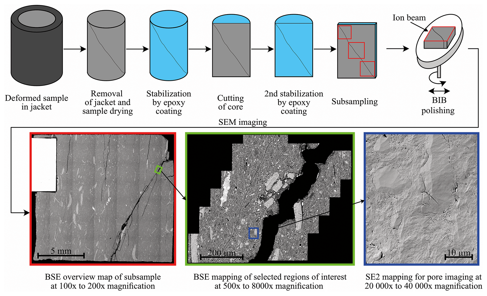
Figure 2Procedure of sample preparation and workflow for microstructural analysis including the twofold stabilisation the broad ion-beam polishing and the imaging strategy.
SEM imaging was conducted using a Zeiss SUPRA-55 equipped with SE2 (secondary electron), BSE (back-scattered electron), and EDS (energy-dispersive X-ray) detectors, of which the first was used for phase segmentation, i.e. solid material or pore, and the latter two were used for the identification of mineral phases, i.e. heavy or light minerals and chemical composition. The workflow for the microstructural image analysis consisted of producing overview BSE-SEM maps at 100× to 150× magnification, and for a detailed analysis at grain scale, BSE and SE2 images were taken from regions of interest at various magnifications from 5000× to 40 000×. Additionally, EDS-element maps were created in combination with BSE images for a more quantitative determination of mineralogy.
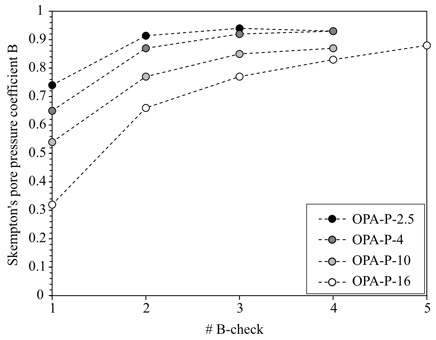
Figure 3Skempton B values demonstrating the saturation of the samples. Experiments are numbered according to the sequence of performance with increasing effective consolidation stresses used, i.e. 2.5, 4, 10, and 16 MPa.
3.1 Hydro-mechanical behaviour
Table 1 shows the water content before and after testing, and Fig. 3 shows the successive Skempton B values indicating complete saturation according to the above-defined criteria. The test configurations and experimental results are summarised in Table 2. A linear–elastic behaviour was only observed in the very low differential stress region due to the early onset of yielding of OPA (Fig. 4). The results show an increasing Young's modulus and a decreasing Poisson's ratio with increasing effective confining stress (Table 2). We define the transition from elasticity to plasticity, i.e. the irreversible, permanent strain, as the onset of yielding determined by the shear stress at which the axial stress–strain curve deviates from linearity (Brace et al., 1966). Yielding, peak, and residual stresses increased with increasing effective confining stresses (Table 2, Fig. 4). The axial strain at which peak strength was reached increased with effective consolidation stress from 0.44 % to 1.11 %. All tests showed a strain softening behaviour in the post-peak region. The residual effective strength was established after 1.5 % to 2.5 % axial strain indicated by only minor stress or pore pressure changes in the range of 0.01 MPa h−1.
Table 1Water content of samples before and after the experiment indicating the re-saturation of the samples.
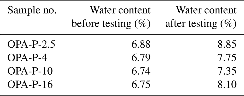
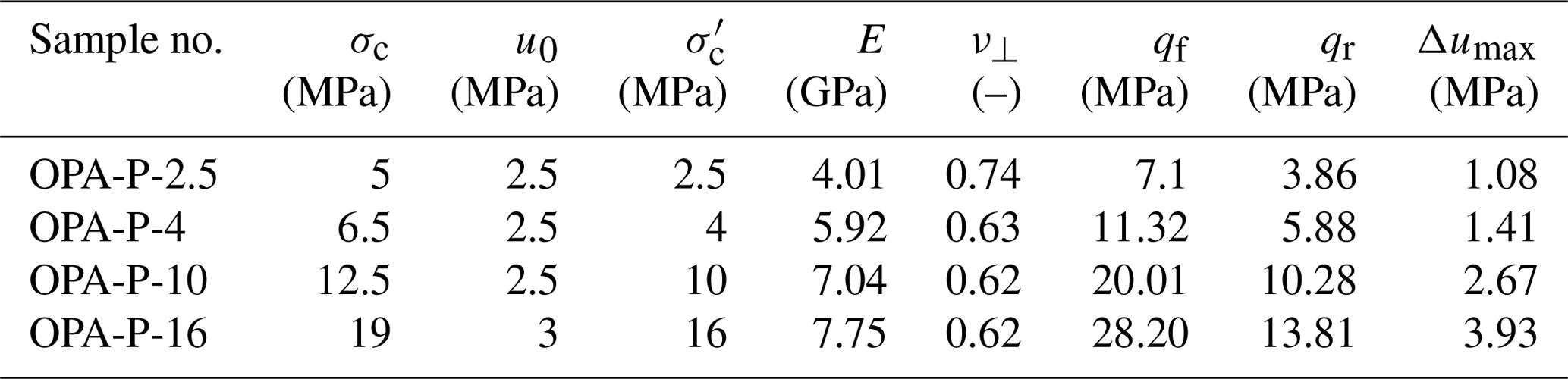
Table 2Overview of experimental parameters (σc: total confining stress; u0: initial pore water pressure before shearing; : effective confining stress before shearing) and elastic (E: Young's modulus; ν⊥: Poisson's ratio), hydro-mechanical, and strength parameters (qf: differential stress at failure; qr: residual differential stress; Δumax: maximum change in pore pressure during shearing phase).
The complete effective stress paths for all experiments are presented in Fig. 5. We infer volumetric net dilation of the sample from the pore pressure peak during the shearing phase. The onset of net dilation (Table 2) took place before peak stress was reached indicating dilation before failure. Both peak and residual strength values showed a non-linear increase with mean effective stress (Fig. 5). A particular difference between the tests at different effective confining stresses was the pore pressure response in the post-peak region. For lower effective confinement (–4 MPa), the post-failure pore pressure approached its initial consolidation pore pressure, i.e. approaching the theoretical drained stress path (grey lines in Fig. 5). For higher effective confinements (–16 MPa) the residual pore pressure was 33 % ( MPa) and 61 % ( 16 MPa) higher than the initial consolidation pore pressure.
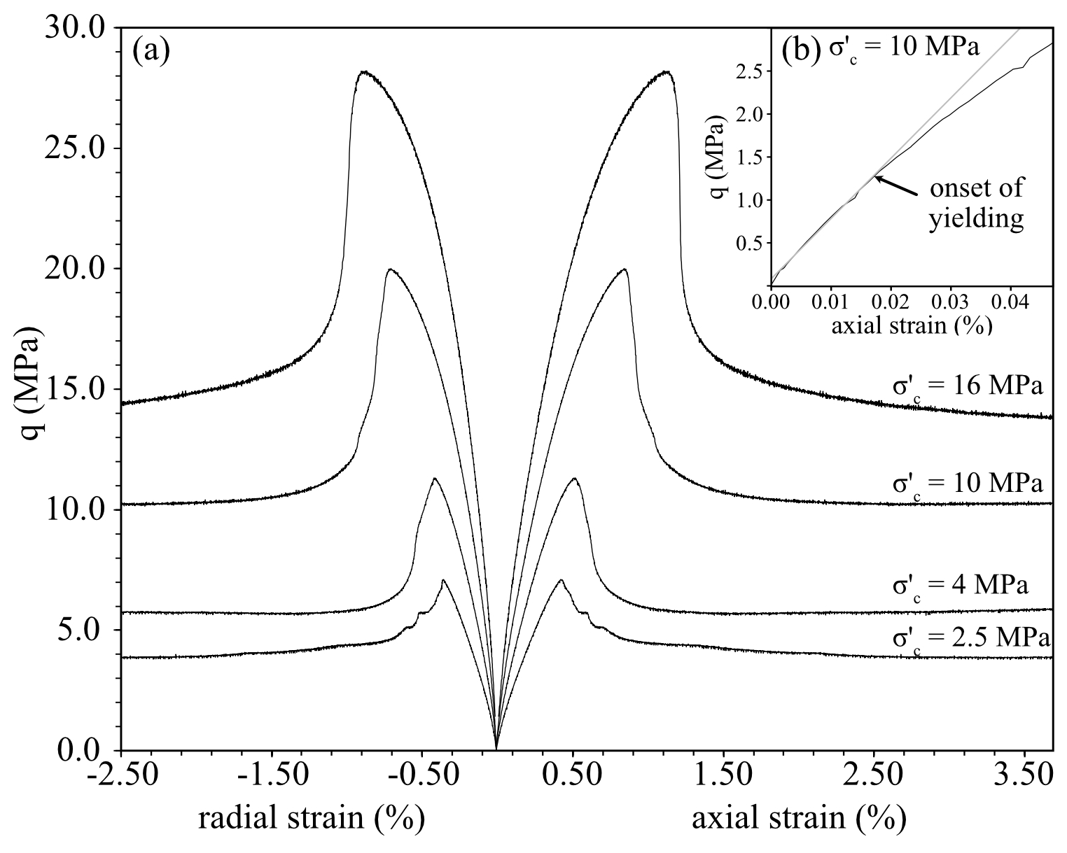
Figure 4(a) Differential stress–strain curves of all tests, where radial strain is measured normal to the bedding plane. Panel (b) shows the early linear–elastic strain region for test OPA-P-10. The linear fit (grey line) is used to constrain the elastic parameters and the deviation from linearity, i.e. the onset of yielding.
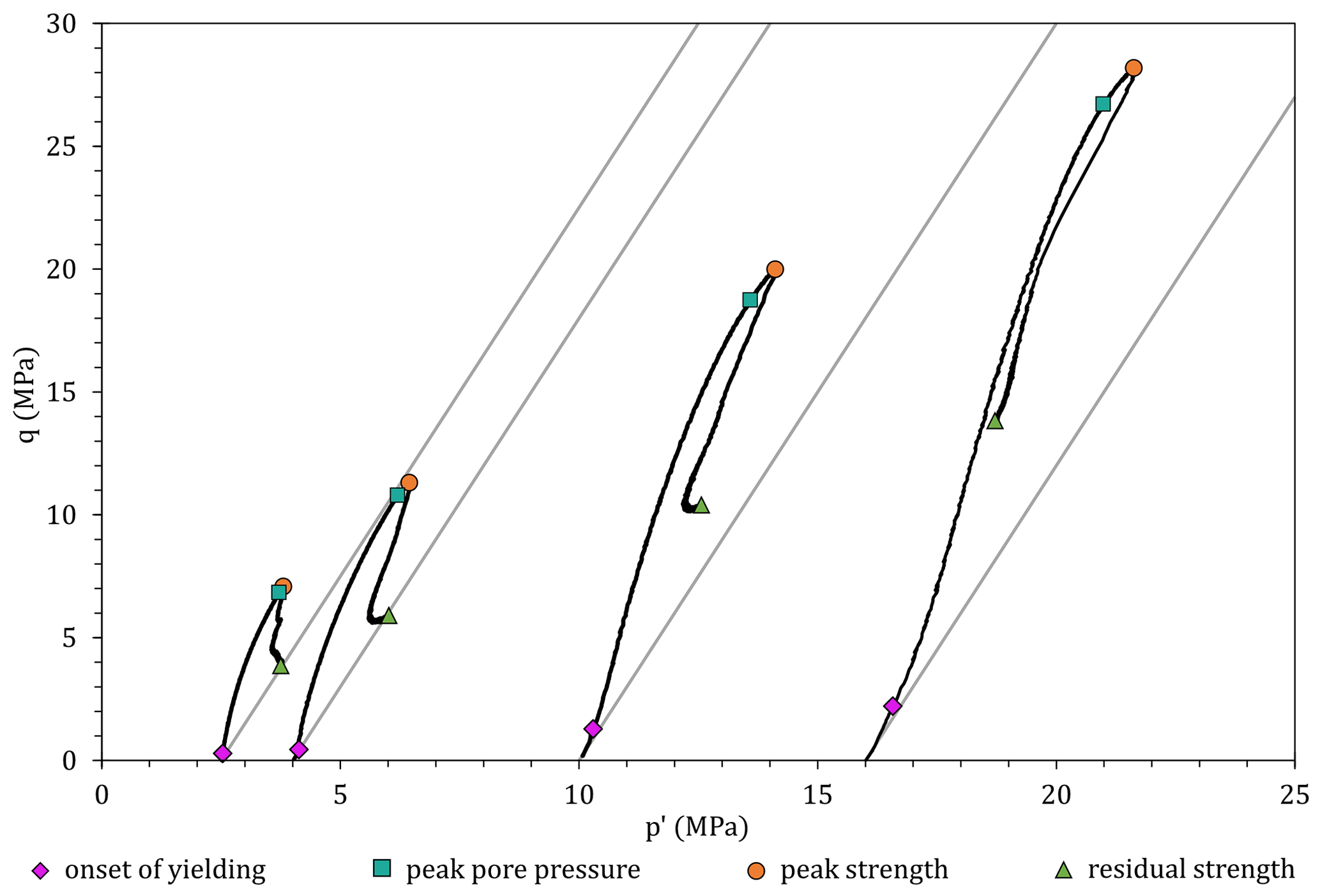
Figure 5Effective stress paths for samples with consolidation stresses 2.5, 4, 10, and 16 MPa. The grey lines represent the theoretical drained stress path, i.e. constant pore pressures.
3.2 Deformation microstructures
The macro-structural analysis of the sample deformed at 2.5 MPa effective confining stress showed a deformation pattern expressed by multiple sub-parallel shear fractures distributed within the sample. The samples tested at effective confining stresses of 4 MPa or higher revealed multiple shear fractures, which concentrated in the form of a central shear band crossing the entire sample (Fig. 6). The macroscopic shear band width was variable across each sample and increased slightly with increasing effective confinement up to widths of 2 mm. The inclination of shear fractures or the shear bands decreased from 70 to 63.5∘ with increasing effective confinement.

Figure 6Macroscopic structures of deformed samples show shear bands, whose inclinations decrease with respect to the horizontal with higher effective confinements. BSE images show the mesoscopic view of the shear band, consisting of multiple shear fractures (a) and (b), and elongated calcite grains present the relative shear displacement. We note here that based on our structural interpretation, the bedding orientation of one sample (σc=2.5 MPa) is inclined by 84∘ instead of 90∘ from the horizontal. However, we consider this small discrepancy of 6∘ insignificant for the analysis.
On the mesoscale, i.e. at the millimetre to hundreds of micrometre scale, the macroscopic shear bands consist of a network of multiple shear fractures (Fig. 6a, b). For all specimens, a larger, continuous main fracture was observed, which was accompanied by surrounding parallel and sub-parallel fractures. The amount of these accompanying shear fractures decreases for higher effective consolidation stresses. Fractures at this scale cross the bedding at angles, which are equal to the inclination of the macroscopic shear band. Locally, relative shear displacements were identified, where fractures cross elongated calcite grains oriented sub-parallel or normal to the shear direction resulting in kinking of these elongated components (Fig. 6c, d).
On the grain scale, the microstructure in the vicinity of the macroscopic shear bands was characterised by bands of localised deformation, i.e. shear zones. In these shear zones, the grain orientation changed compared to the non-sheared host rock from less preferred to highly preferred orientations parallel to the macroscopic shear band with increasing effective stresses. Within these zones, crushed or strained fossil shells and framboidal pyrite aggregates were frequently observed. The intensity of straining and crushing increased with increasing effective confining stress (compare Figs. 7 and 8).
At low effective confinements, no consistent preferred grain orientation was observed, except for occasional encounters of 1–2 µm thin layers constituting the shear zone boundary (Y shears, see Logan et al., 1979). Further, the shear zone was comprised of disrupted and loosened grains as well as microlithons with a size of up to 50 µm. Transgranular fractures formed in quartz, calcite, mica, and siderite grains inside the shear zone. A pronounced feature exclusively observed in the sample at low effective confinement ( MPa) was kink banding (Fig. 7a, a'). Inside these bands, the grain orientation changed the direction by up to 90∘ along a sharp border. Kink bands were also present as Ca-bearing veins revealed by EDS images (Fig. 7b, b'), which formed buckles oriented in direction of the minimum principal stress.

Figure 7SEM images presenting mesoscopic and microscopic deformation structures for the samples deformed at 2.5 MPa effective consolidation stress. Panel (a) shows a network of multiple, anastomosing fractures constituting one of the main shear fractures observed on the macro scale. Panel (a') shows kinking of minerals and disrupted, randomised microfabric in a shear zone. Panel (b) displays a dilatant kink band, which is characterised by a sharply kinked Ca-bearing vein observed in the EDS image (b').
At 4 and 10 MPa effective confinement, the shear zones showed internal bands of preferred grain orientation parallel to the microscopic and macroscopic shear zone orientation (Fig. 9 for MPa). Distinct observations were made for the orientation of elongated grains and pores: outside the shear zone, grains and pores are oriented parallel to the macroscopic bedding and the direction of the maximum principal stress (Fig. 9: rose diagrams, black colour). Within the shear zone, both grains and pores showed different orientations spreading approximately 35–40∘ but show an average orientation aligned with the microscopic and macroscopic orientation of the shear band (Fig. 9: rose diagrams, red colour) and demonstrate the self-similarity of deformation structures across different scales. The shear zone was characterised by internal and “bordering” bands of (sub-)parallel-oriented grains, i.e. Y shears, and obliquely oriented grains, i.e. P foliation (see Logan et al., 1979), with respect to the shear zone boundary (Fig. 10). Open fractures along these bands contained patches of a few micrometre up to 2 mm in size showing slickensides with striations in a normal-to-surface view (Fig. 9c). The apparent porosity in the shear zone was highly increased by voids formed by trans- and intergranular fractures (Fig. 9b).
While the shear zone boundary appeared as a sharp transition for lower to intermediate effective stresses, mainly demonstrated by the increased intergranular porosity and the change in preferred grain orientation within the shear zone (Fig. 9). This sharp transition was less pronounced for the sample tested at 16 MPa effective confining stress (Fig. 8c). Here, the shear zone was accompanied by a broader zone of up to 200 µm width, in which the grain orientation rotated continuously until it was aligned parallel to the shear zone orientation. This transition zone hosted larger elongated calcite and mica grains, which were bent towards the shear zone orientation showing a continuous rotation of up to 135∘. Calcite grains presented flexural tension fractures, which were filled by clay particles (Fig. 8b). Mica grains were stretched and folded showing an intracrystalline sub-grain sliding and rotation. Ductile stringers were found as heavily folded organic-matter particles (Fig. 8b). Within the shear zone, grains were aligned parallel to the macroscopic shear band orientation. Here, single hard grains such as quartz were mainly intact, but transgranular shear fractures were partly also observed (Fig. 8c). The visible shear zone porosity was less increased compared to those in the samples at lower effective stresses.

Figure 8SEM-BSE images presenting deformation structures of the samples tested at 16 MPa effective confinement. Panel (a) shows the rotating fabric in the transition zone, which aligns to the shear zone. Panel (b) presents typical grain-scale deformation markers such as intracrystalline rotational sliding, and stretching of fossil shells. Larger, elongated calcite grains hosts intragranular flexural fractures. Panel (c) displays inter and intracrystalline sliding of phyllosilicates and strained fossil shells leaving crushed trails aligned parallel to the shear zone direction.
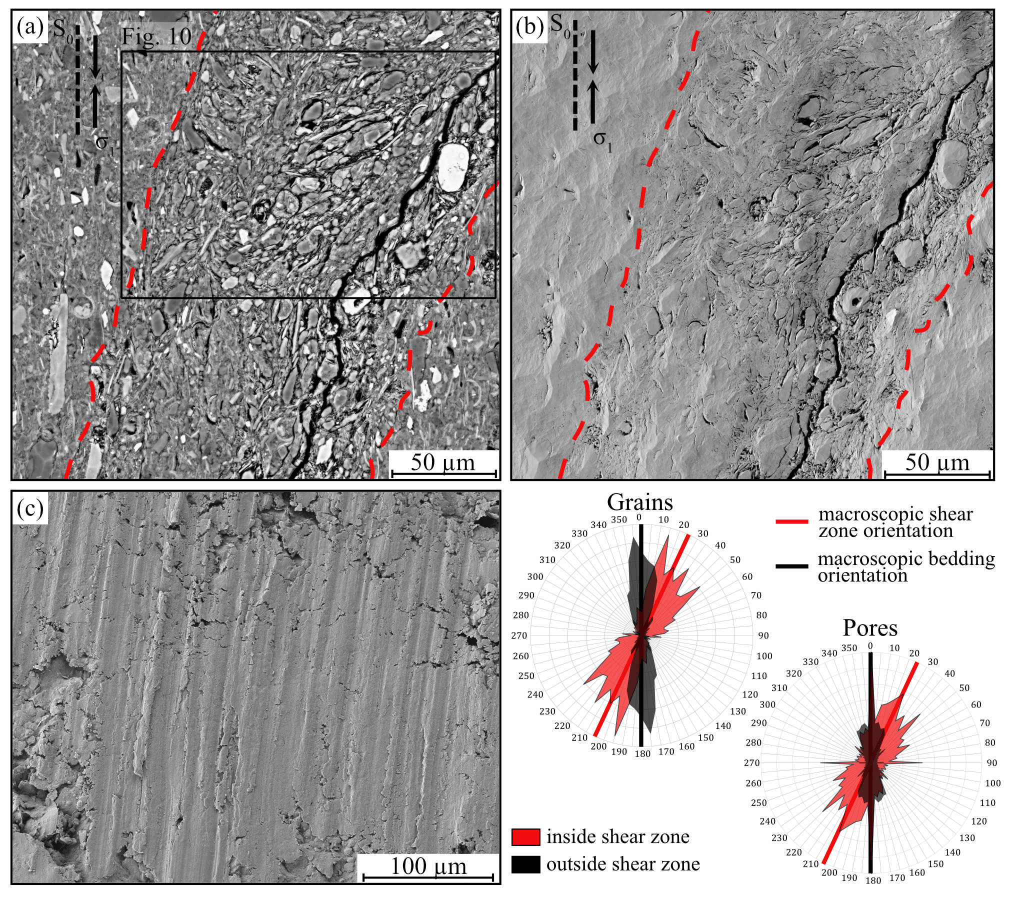
Figure 9SEM images of the sample deformed at 4 MPa effective confinement presenting the shear zone as well as orientations of grains, pores, and macroscopic structures. Panel (a) shows grain orientation (BSE image), (b) shows the increased apparent porosity in the shear zone, and (c) displays the surface morphology of a shear plane (both SE2 images). Rose diagrams of grains and pore within and outside of the shear zones indicate the self-similarity of structure orientations across different scale magnitudes.
4.1 Poromechanical response
All samples showed a bulk deformation behaviour typical for an over-consolidated rock under undrained triaxial compression. As presented in previous studies (Amann et al., 2012; Wild and Amann, 2018a), the onset of yielding, also called “onset of dilation”, starts in the early stage of differential loading. Wild and Amann (2018a) showed that the shear stress magnitude at the onset of the inelastic strain response depends on the effective consolidation stress and increases with increasing effective confinement, which was also observed in this study. The high values for the Poisson's ratio, i.e. 0.62–0.74, deviate considerably from 0.5 as expected for perfectly linear isotropic materials. Theoretically, for transversal isotropic elastic material, the Poisson's ratio perpendicular to the plane of anisotropy can be larger than 0.5 since it is not an independent material parameter. The results are in agreement with similar tests on Opalinus Clay by Minardi et al. (2021). In their study, the Poisson's ratio was measured for both lateral directions showing on average a higher value normal to bedding compared to parallel to bedding by a factor of 3 resulting in an averaged Poisson's ratio of 0.4. Braun et al. (2021) have reported similar findings for the Callovo-Oxfordian argillite. This observation can be explained by the structural anisotropy of the shale, which favours deformation more in a direction normal to bedding due to the preferred alignment of minerals and pores parallel to the bedding plane. The higher Poisson's ratio at lower effective confinements indicates more lateral deformation perpendicular to the bedding plane than for higher effective confining stresses.
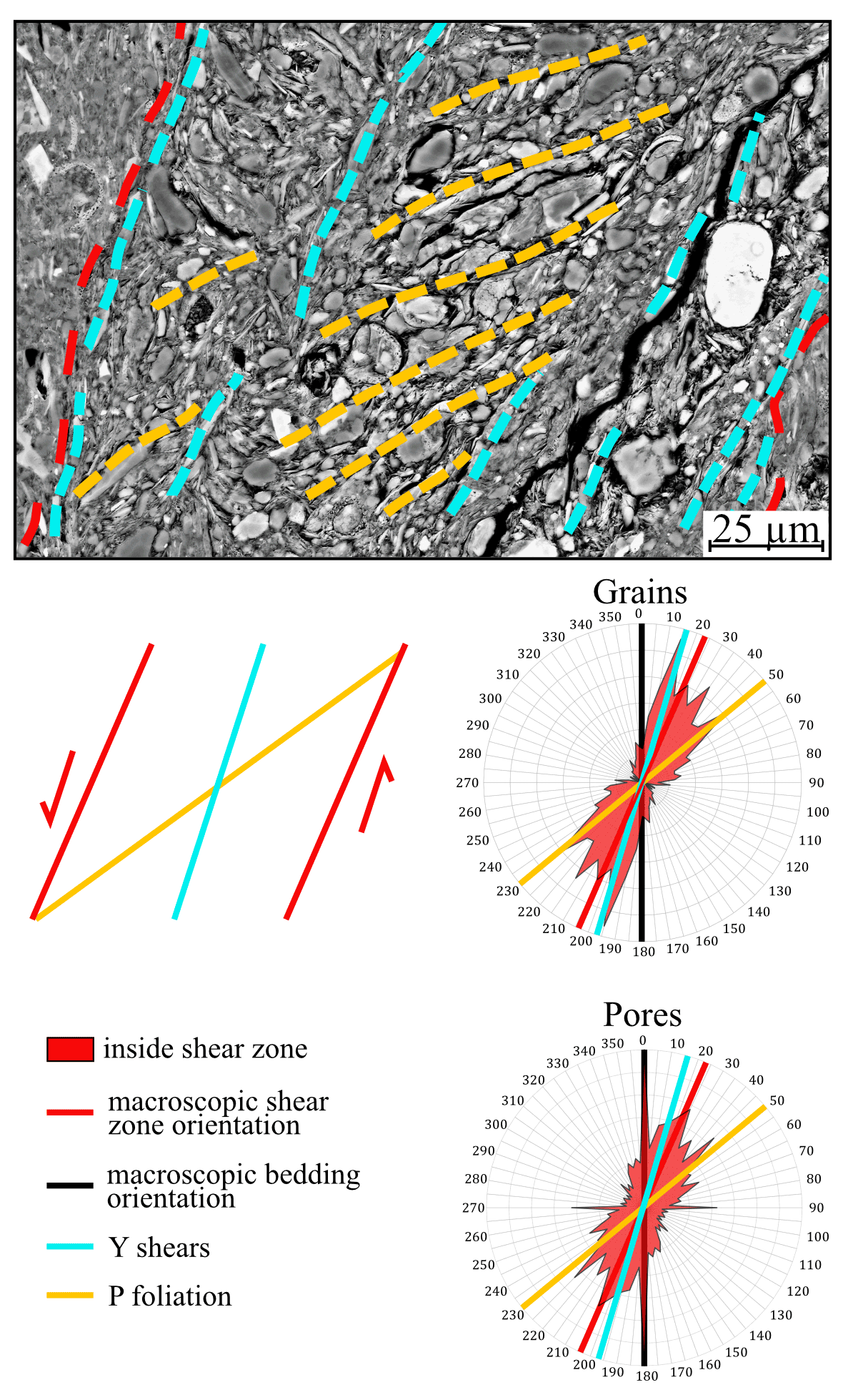
Figure 10Structures mapped in the shear zone (zoom-in from Fig. 9). Grain and pore orientation indicate the development of Y shears and P foliation, which are both represented by orientation peaks of grains.
The peak of pore pressure was reached before the peak stress for all samples tested, and a pronounced reduction in pore pressure indicated net dilation before failure. However, the onset of dilation varied for each test. For the specimen at lowest effective confinement ( MPa), the maximum pore pressure was reached at axial strain shortly before peak stress compared to axial strain at peak strength. Figure 11a shows the axial strain at the onset of net dilation normalised by the axial strain at failure. In contrast to the onset of yielding, this behaviour shows a non-linearly decreasing trend from 92 % to 80 % of axial strain to the axial strain at peak strength with increasing effective confinement. This observation suggests that at high effective confining stresses plastic strain associated with dilation starts earlier compared to low effective confinements, and consequently plastic strain accumulates for a longer period without complete failure.
The magnitude of maximum pore pressure developed under undrained shearing increases in a non-linear fashion (Fig. 11b), which is in agreement with observations made by Wild and Amann (2018a). Furthermore, the effective stress path after failure indicates a less dilatant behaviour for higher effective confinements demonstrated by significantly higher pore water pressures at residual strength state.
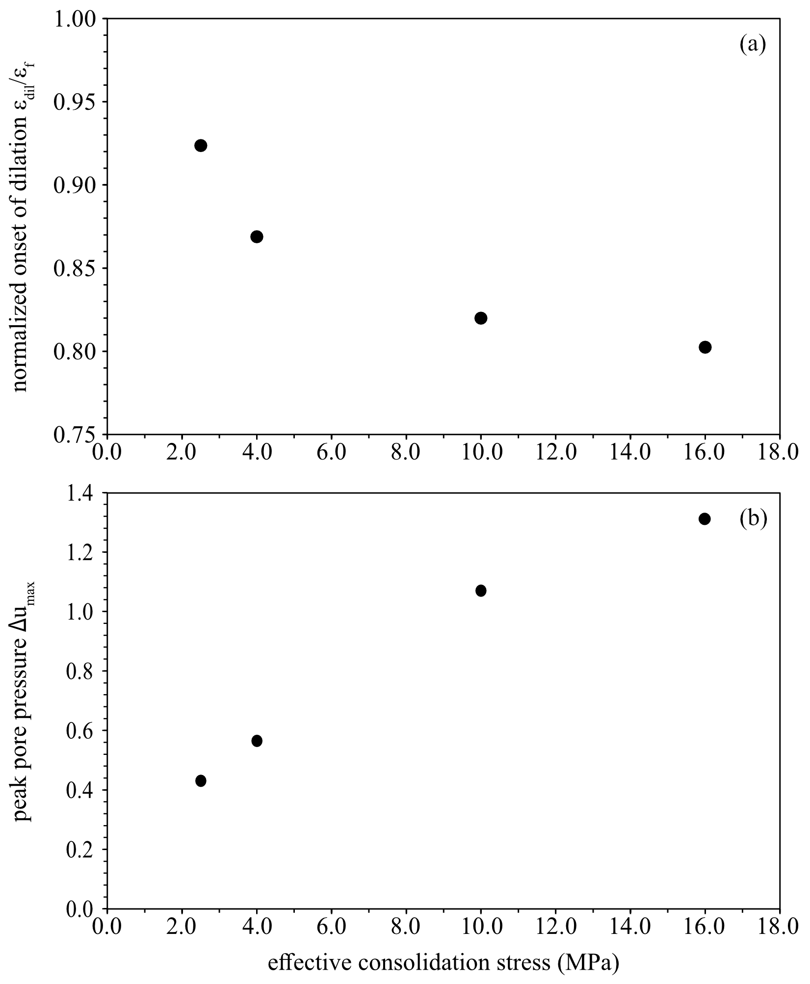
Figure 11(a) Axial strain at the onset of (net) dilation normalised by the respective axial strain at failure indicates an earlier (net) dilation at higher effective stresses. (b) Maximum change in pore water pressure during undrained loading increases with higher effective stresses. Both graphs show a strong non-linearity.
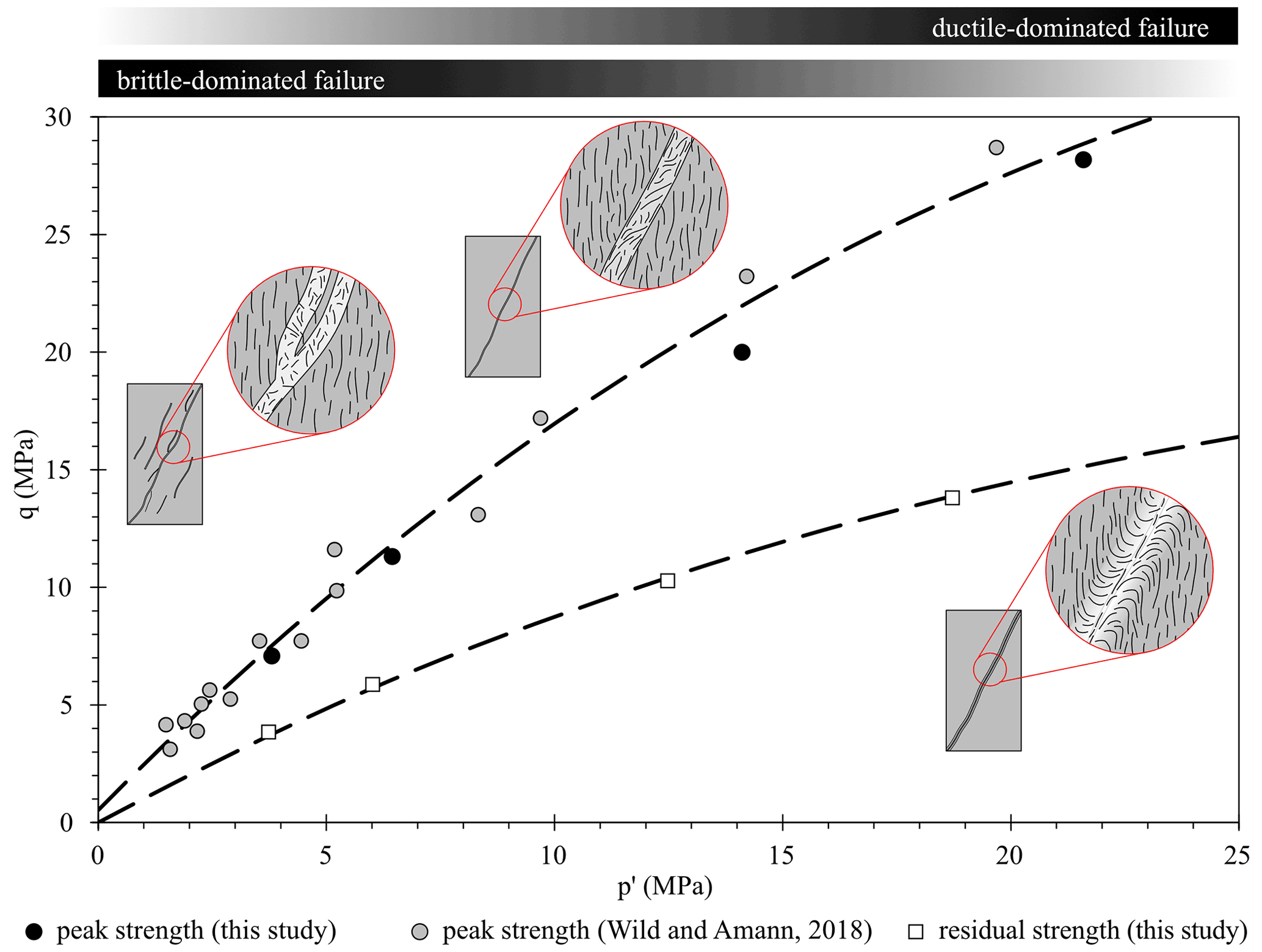
Figure 12Peak and residual effective strength of shaly Opalinus Clay under triaxial undrained compression and our microstructural model for shear failure. The non-linear failure envelopes, fitted through all data points, underline the gradual transition for deformation microstructures from brittle to ductile and the tendency for suppression of dilatancy due to the reduction in shear zone porosity.
4.2 Deformation processes
Even though all samples deformed in a brittle manner in terms of their post-failure strain-softening behaviour and their localised deformation within a shear band or shear fractures on the macroscale, there were major differences in deformation characteristics on the microstructural level. Deformation structures and related processes were strongly dependent on the effective stress. A gradual change has been observed from low effective stresses presenting brittle deformation indicators such as shear fracturing and grain kinking to more ductile processes including inter-particle sliding and grain bending for higher effective confinements. These observations suggest a transition from brittle-dominated shear failure towards a semi-brittle to ductile shearing on the microscale. Underlying deformation mechanisms in the low effective stress range are cataclasis including the formation of multiple shear fractures characterising the shear zone, while at higher effective stresses, deformation is expressed by grain boundary and rotational sliding forming a ductile shear zone (cf. Ramsay and Huber, 1987). Nonetheless, we emphasise that there is a coexistence of brittle and ductile deformation processes on the grain scale as observed also in other studies (Yongnian et al., 1989; Schuster et al. 2021; Winhausen et al., 2021a). This appears to be associated with the contrasting mineral stiffnesses of the constituents such as hard calcite and quartz grains and softer phyllosilicates. In contrast to the shaly facies of OPA from the MT-URL, the sandy facies is characterised by a heterogeneous mineralogy distribution at the macroscale (Lauper et al., 2021; Kneuker and Furche, 2021) and the microscale (Houben et al., 2014). This heterogeneity is also manifested in the distribution and the style of deformation within this facies (Schuster et al., 2021). However, the shaly facies can be considered homogeneous on the millimetre scale (cf. Fig. 6), and deformation processes observed in selected areas of the sub-samples are considered representative of the entire sample and allow for comparing the structures encountered in all samples of this study.
An additional difference in structural deformation was observed for the porosity within the shear zones. While all samples showed an increased shear zone porosity, we observed a decreasing trend with increasing effective confinements. Furthermore, the shear zone width increases with effective confinement and its boundary changes from a sharp boarder (Figs. 7, 9) to a smooth broader transition zone (Fig. 8). These observations are corroborated by the deformation processes analysed above: localised brittle shear fracturing at low effective stresses facilitates more dilation, while ductile shearing suppresses dilation but requires more space for strain accommodation.
These findings are consistent with observations on a suppressed dilation and the reduced magnitude of pore pressure development for higher effective stresses. Furthermore, the earlier dilation before failure at high effective stresses can be related to the formation of the transition zone. The formation of the bent transition zone has been initiated in the pre-failure regime due to fabric rotation and dragging. Once minerals and pores were rotated to a preferred orientation and well-aligned, i.e. to the orientation of the microscopic and macroscopic shear zone/band, bulk failure is initiated. In the post-peak region, most of the shear strain is likely accommodated in the narrow shear zone of preferred mineral orientation, which is in agreement with the slickensides of a considerable size found in the shear zones (Fig. 9c). Here, strongly localised shear strain leads to intercrystalline sliding and eventually to the delamination of phyllosilicates (Fig. 8c).
All samples were sheared to their residual strength where the effective stress remained essentially constant. Thus, we conclude that further straining may not cause structural or void changes, i.e. a critical state. During further shearing, we infer that deformation is accommodated by frictional flow and sliding in the shear zones with preferred mineral orientations, i.e. P foliations, while the fabric elements remain constant (cf. Haines et al., 2013).
4.3 Effective strength and failure mode
A change in failure mode from axial splitting to shear failure has been inferred from macroscopic observations for OPA from unconfined up to confinements of 4 MPa (Amann et al., 2011, 2012). In this study, we extend this observation to higher effective confinements, and – based on our microstructural analysis – we are able to transfer the bulk geomechanical behaviour to the processes on the microscale level.
The transitional change in failure mode on the microscale correlates well with the bulk failure behaviour. The non-linear changes in stiffness, onset of dilation, dilation magnitude, and peak and residual strength with effective stresses are governed by the changing micro-mechanical processes. For the peak and residual strength, the non-linear failure envelope implies a change in friction angle with increasing effective confinement, which is likely associated with the gradual change in shear band inclination and the transition from brittle- to ductile-dominated deformation. At lower effective stresses, micro-cracking and multiple shear fracturing require more shear stress to overcome higher internal frictional resistances compared to intergranular grain boundary sliding and bending at higher effective stresses.
The decrease in friction angle due to an increase in ductility has also been demonstrated experimentally for saturated kaolinite and bentonite clays (Hicher et al., 2000). For the case of clay-rich rocks such as shales, Niandou et al. (1997) have shown that the failure surface of Tournemire Shale is non-linear and the failure mode depends on the confining stress.
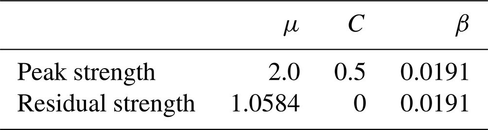
To constrain a failure criterion for peak and residual strength, we combine our results with those of Wild and Amann (2018a) (Fig. 12). As opposed to the linear and bi-linear failure criteria established in past studies for OPA (Amann et al., 2012; Favero et al., 2018; Minardi et al., 2021; Wild and Amann, 2018a), we propose a non-linear envelope for the ultimate and residual strength as derived for other clays (e.g. Bishop et al., 1965; Petley, 1999). Therefore, we use the modified constitutive equation (Eq. 1) to describe the failure surface in 2D q–p′ space proposed for geologic materials by Desai et al. (1984). To fit this model to the data presented in Fig. 5, the parameters shown in Table 3 were used, where q is the differential stress at peak and residual strength in megapascal, respectively, p′ is the mean effective stress in megapascal, and µ, C, and β are fitting parameters.
Table 3Parameters used for fitting the failure surface constrained by Eq. (1) to our data and those of Wild and Amann (2018a).
4.4 Implication for the storage of radioactive waste
For the application as a host rock for nuclear waste, the findings on the hydro-mechanical and deformation behaviour of Opalinus Clay can be transferred to predict the in situ behaviour of the rock mass. During the construction of the repository, excavation-induced damage in Opalinus Clay and other clay-rich rocks regarded as potential host rocks has been reported in many studies (e.g. Bossart et al., 2002; Nussbaum et al., 2011; Lanyon et al., 2015; Yong et al., 2017). However, studies focusing on the structures developed in response to induced stress changes were limited to macro- and mesoscale observations differentiating between shear and extensional fractures (Labiouse and Vietor, 2014; Armand et al., 2014; Kupferschmied et al., 2015). This study provides insight into the deformation behaviour and processes on the microscale, which differ depending on the mean effective stress. Hence, the expression of excavation-induced damage likely changes with distance from the tunnel as mean stresses change. In particular, at low effective stresses, changes in permeability are more likely to emerge due to the more dilatant behaviour and the increased shear zone porosity. Remaining questions arise if the deformation behaviour observed also applies to long-term deformation associated with creep and elevated temperature developing after waste storage. The latter might cause changes in mineralogy, particularly in the clay mineralogy, which can lead to hydro-mechanical changes in the physical behaviour of the rock.
In consolidated undrained triaxial compression, Opalinus Clay shows a transitional failure behaviour from brittle- to ductile-dominated deformation with increasing effective confining stress. Although in a classical sense, the general bulk behaviour can be described as brittle deformation due to the early failure (<1.5 εax), the strain-softening behaviour in the post-peak phase, and the localised strain in distinct shear bands, our results suggest these indicators are insufficient to properly describe the failure mechanism. Instead, we highlight the significance of micro-mechanical processes on the microscale governing the failure mode and controlling the rheology of the material.
Our results demonstrate the transition in failure mode by, firstly, the non-linear dependency of hydro-mechanical properties on effective stress, i.e. the onset of net dilation, the magnitude of developed pore pressure, and peak and residual strength, and, secondly, the structural deformation processes changing from brittle-dominated to ductile-dominated failure on the microscale. This transition is accompanied by a decreasing porosity in the shear zone and a less pronounced dilation with increasing effective confining stresses. Our conceptual microstructural model (Fig. 12) for shear failure in Opalinus Clay is characterised by a set of multiple, distinct, and dilatant shear zones with brittle-dominated deformation for lower effective stresses in the range of 2.5 MPa effective stress at failure. For effective stresses around 4 to 10 MPa, OPA shows a transitional failure mode. For effective confining stresses in the range of 16 MPa and expectedly higher stresses, failure on the microscale is less dilatant forming a broader shear zone dominated by ductile deformation. Based on these observations, we propose a non-linear failure criterion to describe the behaviour of shaly Opalinus Clay.
The triaxial test data and high-resolution SEM images for this article are available online at: https://osf.io/CD27S/ (Winhausen et al., 2021b).
LW performed the laboratory tests, BIB-SEM microscopy, and data analysis and wrote the paper with contributions from all authors. LW, KK, MJ, and JLU discussed the results. FA acquired funding and contributed to the interpretation of the results.
The contact author has declared that neither they nor their co-authors have any competing interests.
Publisher’s note: Copernicus Publications remains neutral with regard to jurisdictional claims in published maps and institutional affiliations.
We would like to thank the Swiss Federal Nuclear Safety Inspectorate (ENSI) for funding this work, which was performed within the framework of the project entitled “Development and Validation of a Constitutive Model for Opalinus Clay”. We thank the two reviewers, Tom Blenkinsop and Mike Chandler, for their constructive comments, which improved the paper.
This research has been supported by the RWTH Aachen University and Swiss Federal Nuclear Safety Inspectorate (ENSI).
This open-access publication was funded by the RWTH Aachen University.
This paper was edited by David Healy and reviewed by Thomas Blenkinsop and Mike Chandler.
Amann, F., Button, E. A., Evans, K. F., Gischig, V. S., and Blümel, M.: Experimental Study of the Brittle Behavior of Clay shale in Rapid Unconfined Compression, Rock Mech. Rock Eng., 44, 415–430, https://doi.org/10.1007/s00603-011-0156-3, 2011.
Amann, F., Kaiser, P., and Button, E. A.: Experimental Study of Brittle Behavior of Clay Shale in Rapid Triaxial Compression, Rock Mech. Rock Eng., 45, 21–33, https://doi.org/10.1007/s00603-011-0195-9, 2012.
Armand, G., Leveau, F., Nussbaum, C., de La Vaissiere, R., Noiret, A., Jaeggi, D., Landrein, P., and Righini, C.: Geometry and properties of the excavation-induced fractures at the Meuse/Haute-Marne URL drifts, Rock Mech. Rock Eng., 47, 21–41, https://doi.org/10.1007/s00603-012-0339-6, 2014.
Attewell, P. B. and Sandford, M. R.: Intrinsic Shear Strength of a Brittle, Anisotropic Rock – I: Experimental and Mechanical Interpretation, Int. J. Rock Mech. Min. Sci. Geom. Abstr., 11, 423–430, 1974.
Bésuelle, P., Viggiani, G., Desrues, J., Coll, C., and Charrier, P.: A Laboratory Experimental Study of the Hydromechanical Behavior of Boom Clay, Rock Mech. Rock Eng., 47, 143–155, https://doi.org/10.1007/s00603-013-0421-8, 2014.
Bishop, A. W., Webb, D. L., and Lewin, P. I.: Undisturbed Samples of London Clay from the Ashford Common Shaft: Strength–Effective Stress Relationships, Géotechnique, 15, 1–31, https://doi.org/10.1680/geot.1965.15.1.1, 1965.
Bossart, P., Meier, P. M., Moeri, A., Trick, T., and Mayor, J. C.: Geological and hydraulic characterisation of the excavation disturbed zone in the Opalinus Clay of the Mont Terri Rock Laboratory, Eng. Geol., 66, 19–38, https://doi.org/10.1016/S0013-7952(01)00140-5, 2002.
Brace, W. F., Paulding, B. W., and Scholz, C.: Dilatancy in the fracture of crystalline rocks, J. Geophys. Res., 71, 3939–3953, https://doi.org/10.1029/JZ071i016p03939, 1966.
Braun, P., Ghabezloo, S., Delage, P., Sulem, J., and Conil, N.: Transversely Isotropic Poroelastic Behaviour of the Callovo-Oxfordian Claystone: A Set of Stress-Dependent Parameters, Rock Mech. Rock Eng., 54, 377–396, https://doi.org/10.1007/s00603-020-02268-z, 2021.
Byerlee, J. D.: Brittle-ductile transition in rocks, J. Geophys. Res., 73, 4741–4750, https://doi.org/10.1029/JB073i014p04741, 1968.
Delage, P. and Tessier, D.: Macroscopic effects of nano and microscopic phenomena in clayey soils and clay rocks, Geomech. Energ. Environ., 27, 100177, https://doi.org/10.1016/j.gete.2019.100177, 2021.
Desai, C. S. and Siriwardane, H. J.: Constitutive laws for engineering materials, with emphasis on geologic materials, Prentice Hall, 468 pp., ISBN 0-13-167940-6, 1984.
Desbois, G., Höhne, N., Urai, J. L., Bésuelle, P., and Viggiani, G.: Deformation in cemented mudrock (Callovo–Oxfordian Clay) by microcracking, granular flow and phyllosilicate plasticity: insights from triaxial deformation, broad ion beam polishing and scanning electron microscopy, Solid Earth, 8, 291–305, https://doi.org/10.5194/se-8-291-2017, 2017.
Djéran-Maigre, I., Tessier, D., Grunberger, D., Velde, B., and Vasseur, G.: Evolution of microstructures and of macroscopic properties of some clays during experimental compaction, Mar. Petrol. Geol., 15, 109–128, https://doi.org/10.1016/S0264-8172(97)00062-7, 1998.
Evans, B., Fredrich, J. T., and Wong, T.: The brittle-ductile transition in rocks: Recent experimental and theoretical progress, in: Geophysical Monograph Series, Vol. 56, edited by: Duba, A. G., Durham, W. B., Handin, J. W., and Wang, H. F., American Geophysical Union, Washington, DC, 1–20, https://doi.org/10.1029/GM056p0001, 1990.
Favero, V., Ferrari, A., and Laloui, L.: Anisotropic Behaviour of Opalinus Clay Through Consolidated and Drained Triaxial Testing in Saturated Conditions, Rock Mech. Rock Eng., 51, 1305–1319, https://doi.org/10.1007/s00603-017-1398-5, 2018.
Goetze, C.: High temperature rheology of westerly granite, J. Geophys. Res., 76, 1223–1230, https://doi.org/10.1029/JB076i005p01223, 1971.
Gramberg, J.: The axial cleavage fracture 1 Axial cleavage fracturing, a significant process in mining and geology, Eng. Geol., 1, 31–72, https://doi.org/10.1016/0013-7952(65)90006-2, 1965
Griggs, D. and Handin, J.: Observations on fracture and a hypothesis of earthquakes, book chapter in Rock Deformation (A Symposium), edited by: Griggs, D. and Handin, GSA MEMOIRS, chap. 13, 347–364, https://doi.org/10.1130/MEM79, 1960.
Haines, S. H., Kaproth, B., Marone, C., Saffer, D., and van der Pluijm, B.: Shear zones in clay-rich fault gouge: A laboratory study of fabric development and evolution, J. Struct. Geol., 51, 206–225, https://doi.org/10.1016/j.jsg.2013.01.002, 2013.
Handin, J., Hager Jr., R. V., Friedman, M., and Feather, J. N.: Experimental deformation of sedimentary rocks under confining pressure: pore pressure tests, AAPG Bull., 47, 717–755, 1963.
Hattab, M. and Fleureau, J.-M.: Experimental analysis of kaolinite particle orientation during triaxial path, Int. J. Numer. Anal. Meth. Geomech., 35, 947–968, https://doi.org/10.1002/nag.936, 2011.
Hattab, M., Hammad, T., Fleureau, J.-M., and Hicher, P.-Y.: Behaviour of a sensitive marine sediment: microstructural investigation, Géotechnique, 63, 71–84, https://doi.org/10.1680/geot.10.P.104, 2013.
Heard, H. C.: Transition from brittle fracture to ductile flow in Solenhofen limestone as a function of temperature, confining pressure, and interstitial fluid pressure, book chapter in Rock Deformation (A Symposium), edited by: Griggs, D. and Handin, GSA MEMOIRS, chap. 7, 193–226, https://doi.org/10.1130/MEM79-p193,1960.
Hicher, P. Y., Wahyudi, H., and Tessier, D.: Microstructural analysis of inherent and induced anisotropy in clay, Mech. Cohes.-Frict. Mater., 5, 341–371, 2000.
Houben, M. E., Desbois, G., and Urai, J. L.: A comparative study of representative 2D microstructures in Shaly and Sandy facies of Opalinus Clay (Mont Terri, Switzerland) inferred form BIB-SEM and MIP methods, Mar. Petrol. Geol., 49, 143–161, https://doi.org/10.1016/j.marpetgeo.2013.10.009, 2014.
Ibanez, W. D. and Kronenberg, A. K.: Experimental deformation of shale: Mechanical properties and microstructural indicators of mechanisms, Int. J. Rock Mech. Min. Sci. Geomech. Abstr., 30, 723–734, https://doi.org/10.1016/0148-9062(93)90014-5, 1993.
Ingram, G. M. and Urai, J. L.: Top-seal leakage through faults and fractures: the role of mudrock properties, Geol. Soc. Lond. Spec. Publ., 158, 125–135, https://doi.org/10.1144/GSL.SP.1999.158.01.10, 1999.
Klinkenberg, M., Kaufhold, S., Dohrmann, R., and Siegesmund, S.: Influence of carbonate microfabrics on the failure strength of claystones, Eng. Geol., 107, 42–54, https://doi.org/10.1016/j.enggeo.2009.04.001, 2009.
Kneuker, T. and Furche, M.: Capturing the structural and compositional variability of Opalinus Clay: constraints from multidisciplinary investigations of Mont Terri drill cores (Switzerland), Environ. Earth Sci., 80, 421, https://doi.org/10.1007/s12665-021-09708-1, 2021.
Kranz, R. L.: Microcracks in rocks: A review, Tectonophysics, 100, 449–480, https://doi.org/10.1016/0040-1951(83)90198-1, 1983.
Kupferschmied, N., Wild, K.M., Amann, F., Nussbaum, C., Jaeggi, D., and Badertscher, N.: Time-dependent fracture formation around a borehole in a clay shale, Int. J. Rock Mech. Min. Sci., 77, 105–114, https://doi.org/10.1016/j.ijrmms.2015.03.027 ,2015.
Labiouse, V. and Vietor, T.: Laboratory and in situ simulation tests of the excavation damaged zone around galleries in Opalinus Clay, Rock Mech. Rock Eng., 47, 57–70, https://doi.org/10.1007/s00603-013-0389-4, 2014.
Lanyon, G. W., Martin, D., Giger, S., and Marschall, P.: Development and evolution of the Excavation Damage Zone (EDZ) in the Opalinus Clay – A synopsis of the state of knowledge from Mont Terri, NAGRA Arbeitsbericht NAB, Nagra (National Cooperative for the Disposal of Radioactive Waste), 14–87, 2014.
Lauper, B., Zimmerli, G. N., Jaeggi, D., Deplazes, G., Wohlwend, S., Rempfer, J., and Foubert, A.: Quantification of Lithological Heterogeneity Within Opalinus Clay: Toward a Uniform Subfacies Classification Scheme Using a Novel Automated Core Image Recognition Tool, Front. Earth Sci., 9, 645596, https://doi.org/10.3389/feart.2021.645596, 2021.
Logan, J. M., Friedman, M., Dengo, C., Shimamoto, T., and Higgs, N.: Experimental studies of simulated gouge and their application to studies of natural fault zones, U.S. Geological Survey Open File Report 79-1239, 305–343, 1979.
Mäder, U.: Recipe and preparation of a simplified artificial pore water for Opalinus Clay and “Brown Dogger” based on the Nagra reference pore water composition, containing Na-K-Ca-Mg-Cl-SO4-HCO3, and adjusted to atmospheric PCO2, NAGRA AN, NAGRA Report Aktennotiz, 11–159, 2011.
Menéndez, B., Zhu, W., and Wong, T.-F.: Micromechanics of brittle faulting and cataclastic flow in Berea sandstone, J. Struct. Geol., 18, 1–16, https://doi.org/10.1016/0191-8141(95)00076-P, 1996.
Minardi, A., Giger, S. B., Ewy, R. T., Stankovic, R., Stenebråten, J., Soldal, M., Rosone, M., Ferrari, A., and Laloui, L.: Benchmark study of undrained triaxial testing of Opalinus Clay shale: Results and implications for robust testing, Geomech. Energ. Environ., 25, 100210, https://doi.org/10.1016/j.gete.2020.100210, 2021.
Mogi, K.: Pressure Dependence of Rock Strength and Transition from Brittle Fracture to Ductile Flow, Bull. Earth. Res. Inst., 44, 215–232, 1966.
Morgenstern, N. R. and Tchalenko, J. S.: Microscopic structures in kaolin subjected to direct shear, Geotechnique, 17, 309–328, https://doi.org/10.1680/geot.1967.17.4.309, 1967.
Niandou, H., Shao, J. F., Henry, J. P., and Fourmaintraux, D.: Laboratory Investigation of the Mechanical Behaviour of Tournemire Shale, Int. J. Rock Mech. Min. Sci., 34, 3–16, https://doi.org/10.1016/S1365-1609(97)80029-9, 1997.
Nussbaum, C., Bossart, P., Amann, F., and Aubourg, C.: Analysis of tectonic structures and excavation induced fractures in the Opalinus Clay, Mont Terri underground rock laboratory (Switzerland), Swiss J. Geosci., 104, 187–210, https://doi.org/10.1007/s00015-011-0070-4, 2011.
Nygård, R., Gutierrez, M., Bratli, R. K., and Høeg, K.: Brittle–ductile transition, shear failure and leakage in shales and mudrocks, Mar. Petrol. Geol., 23, 201–212, https://doi.org/10.1016/j.marpetgeo.2005.10.001, 2006.
Oelker, A.: Deformation properties of Boom Clay: Implementation of a multi-scale concept, No. RWTH-2019-09913. PhD Thesis, RWTH Publifications, https://doi.org/10.18154/RWTH-2019-09913, 2020.
Ramsay, J. G., Huber, M. I., and Lisle, R. J.: The techniques of modern structural geology: Folds and fractures, Vol. 2, Academic press, ISBN 0125769229, 1983.
Petley, D. N.: Failure envelopes of mudrocks at high confining pressures, Geol. Soc. Lond. Spec. Publ., 158, 61–71, https://doi.org/10.1144/GSL.SP.1999.158.01.05, 1999.
Rutter, E. H.: On the nomenclature of mode of failure transitions in rocks, Tectonophysics, 122, 381–387, https://doi.org/10.1016/0040-1951(86)90153-8, 1986.
Sarout, J., Esteban, L., Delle Piane, C., Maney, B., and Dewhurst, D. N.: Elastic anisotropy of Opalinus Clay under variable saturation and triaxial stress, Geophys. J. Int., 198, 1662–1682, https://doi.org/10.1093/gji/ggu231, 2014.
Schuck, B., Desbois, G., and Urai, J. L.: Grain-scale deformation mechanisms and evolution of porosity in experimentally deformed Boom Clay, J. Struct. Geol., 130, 103894, https://doi.org/10.1016/j.jsg.2019.103894, 2020.
Schuster, V., Rybacki, E., Bonnelye, A., Herrmann, J., Schleicher, A. M., and Dresen, G.: Experimental Deformation of Opalinus Clay at Elevated Temperature and Pressure Conditions: Mechanical Properties and the Influence of Rock Fabric, Rock Mech. Rock Eng., 54, 4009–4039, https://doi.org/10.1007/s00603-021-02474-3, 2021.
Sellin, P. and Leupin, O. X.: The Use of Clay as an Engineered Barrier in Radioactive-Waste Management – A Review, Clays Clay Mineral., 61, 477–498, https://doi.org/10.1346/CCMN.2013.0610601, 2013.
Skempton, A. W.: Some observations on tectonic shear zones, 1st ISRM Congress, ISRM-1CONGRESS-1966-057, 1966.
Skempton, A. W.: The pore-pressure coefficients A and B, Géotechnique, 4, 143–147, https://doi.org/10.1680/geot.1954.4.4.143, 1954.
Tchalenko, J. S.: The evolution of kink-bands and the development of compression textures in sheared clays, Tectonophysics, 6, 159–174, https://doi.org/10.1016/0040-1951(68)90017-6, 1968.
Tchalenko, J. S.: Similarities between Shear Zones of Different Magnitudes, Geol. Soc. Am. Bull., 81, 1625–1640, https://doi.org/10.1130/0016-7606(1970)81[1625:SBSZOD]2.0.CO;2, 1970.
Thury, M. and Bossart, P.: The Mont Terri rock laboratory, a new international research project in a Mesozoic shale formation, in Switzerland, Eng. Geol., 52, 347–359, https://doi.org/10.1016/S0013-7952(99)00015-0, 1999.
Wild, K. M. and Amann, F.: Experimental study of the hydro-mechanical response of Opalinus Clay – Part 1: Pore pressure response and effective geomechanical properties under consideration of confinement and anisotropy, Eng. Geol., 237, 32–41, https://doi.org/10.1016/j.enggeo.2018.02.012, 2018a.
Wild, K. M. and Amann, F.: Experimental study of the hydro-mechanical response of Opalinus Clay – Part 2: Influence of the stress path on the pore pressure response, Eng. Geol., 237, 92–101, https://doi.org/10.1016/j.enggeo.2018.02.011, 2018b.
Winhausen, L., Klaver, J., Schmatz, J., Desbois, G., Urai, J. L., Amann, F., and Nussbaum, C.: Micromechanisms leading to shear failure of Opalinus Clay in a triaxial test: a high-resolution BIB–SEM study, Solid Earth, 12, 2109–2126, https://doi.org/10.5194/se-12-2109-2021, 2021a.
Winhausen, L., Khaledi, K., Jalali, M., Urai, J. L., and Amann, F.: Data base for: Failure mode transition in Opalinus Clay: a hydro-mechanical and microstructural perspective, OSF [data set], https://osf.io/cd27s/ date (last access: 13 May 2022), 2021b.
Wong, T., David, C., and Zhu, W.: The transition from brittle faulting to cataclastic flow in porous sandstones: Mechanical deformation, J. Geophys. Res., 102, 3009–3025, https://doi.org/10.1029/96JB03281, 1997.
Yong, S., Loew, S., Schuster, K., Nussbaum, C., and Fidelibus, C.: Characterisation of excavation-induced damage around a short test tunnel in the Opalinus Clay, Rock Mech. Rock Eng., 50, 1959–1985, https://doi.org/10.1007/s00603-017-1212-4, 2017.
Yongnian, H., Chuanyong, L., and Lanbin, S.: Microstructural Features of Deformed Rocks across the Brittle-Ductile Transition, Phys. Chem. Earth, 17, 11–15, https://doi.org/10.1016/0079-1946(89)90003-7, 1989.