the Creative Commons Attribution 4.0 License.
the Creative Commons Attribution 4.0 License.
 | 31 Aug 2023
Analogue experiments on releasing and restraining bends and their application to the study of the Barents Shear Margin
Roy Helge Gabrielsen
Panagiotis Athanasios Giannenas
Dimitrios Sokoutis
Ernst Willingshofer
Muhammad Hassaan
Jan Inge Faleide
The Barents Shear Margin separates the Svalbard and Barents Sea from the North Atlantic. During the break-up of the North Atlantic the plate tectonic configuration was characterized by sequential dextral shear, extension, and eventually contraction and inversion. This generated a complex zone of deformation that contains several structural families of overlapping and reactivated structures.
A series of crustal-scale analogue experiments, utilizing a scaled and stratified sand–silicon polymer sequence, was used in the study of the structural evolution of the shear margin.
The most significant observations for interpreting the structural configuration of the Barents Shear Margin are the following.
-
Prominent early-stage positive structural elements (e.g. folds, push-ups) interacted with younger (e.g. inversion) structures and contributed to a hybrid final structural pattern.
-
Several structural features that were initiated during the early (dextral shear) stage became overprinted and obliterated in the subsequent stages.
-
All master faults, pull-apart basins, and extensional shear duplexes initiated during the shear stage quickly became linked in the extension stage, generating a connected basin system along the entire shear margin at the stage of maximum extension.
-
The fold pattern was generated during the terminal stage (contraction–inversion became dominant in the basin areas) and was characterized by fold axes striking parallel to the basin margins. These folds, however, strongly affected the shallow intra-basin layers.
The experiments reproduced the geometry and positions of the major basins and relations between structural elements (fault-and-fold systems) as observed along and adjacent to the Barents Shear Margin. This supports the present structural model for the shear margin.
- Article
(16323 KB) - Full-text XML
- BibTeX
- EndNote


The physiography, width, and structural style of the Norwegian continental margin vary considerably along its strike (e.g. Faleide et al., 2008, 2015). The margin includes a southern rifted segment between 60 and 70∘ N and a northern sheared–rifted segment between 70 and 82∘ N (Fig. 1a). The latter coincides with the oceanward border of the western Barents Sea and Svalbard margins (e.g. Faleide et al., 2008) and is referred to here as “the Barents Shear Margin”. This segment coincides with the continent–ocean transition (COT) of the northernmost part of the North Atlantic Ocean. Its configuration is typical for that of transform margins where the structural pattern became established in an early stage of shear, later to develop into an active continent–ocean passive margin (Mascle and Blarez, 1987; Lorenzo, 1997; Seiler et al., 2010; Basile, 2015; Nemcok et al., 2016).
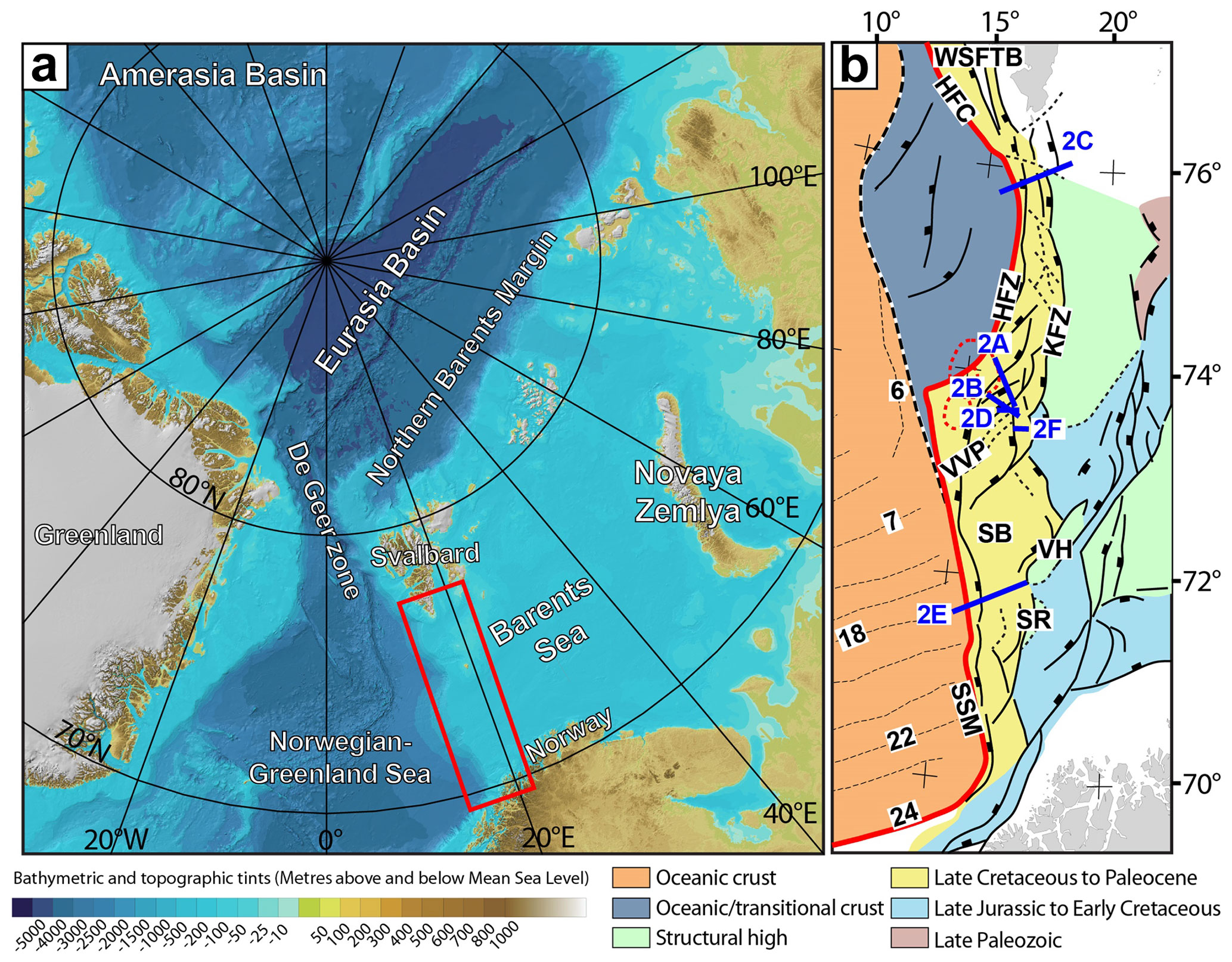
Figure 1(a) The Barents Sea is separated from the Norwegian–Greenland Sea by the de Geer transfer margin. The red box shows the present study area. (b) Structural map of the Barents Shear Margin. Note the segmentation of the continent–ocean transition. Abbreviations (from north to south) – WSFTB: western Spitsbergen fold-and-thrust belt, HFZ: Hornsund Fault Complex, KFC: Knølegga Fault Zone, VVP: Vestbakken Volcanic Province, SB: Sørvestsnaget Basin, VH: Veslemøy High, SR: Senja Ridge, SSM: Senja Shear Margin. Blue lines indicate the position of seismic profiles in Fig. 2, and the red line (X-X') shows the western border of thinned crust (see also Fig. 3). Chron numbers are indicated on oceanic crust area.
Late Cretaceous–Paleocene shear, rifting, break-up, and incipient spreading in the North Atlantic were associated with voluminous magmatic activity, resulting in the development of the North Atlantic Volcanic Province (Saunders et al., 1997; Ganerød et al., 2010; Horni et al., 2017). According to its tectonic development, the Barents Shear Margin (Fig. 1b) incorporates, or is bordered by, several distinct structural elements, some of which are associated with volcanism and halokinesis.
The multi-stage development combined with a complex geometry caused interference between structures (and sediment systems) in different stages of the margin development. Such relations are not always obvious, but interpretation can be supported by scale models. We combine the interpretation of reflection seismic data and analogue modelling. Thus, we investigate structures generated in dextral shear. These were generated during initial dextral shear, the development into seafloor spreading, and subsequent contraction. The later stages (contraction) were likely influenced by plate reorganization (Talwani and Eldholm, 1977; Gaina et al., 2009; see also Vågnes et al., 1998; Pascal and Gabrielsen, 2001; Pascal et al., 2005; Gac et al., 2016) or other far-field stresses (Doré and Lundin, 1996; Lundin and Doré, 1997; Doré et al., 1999, 2016; Lundin et al., 2013). The present experiments were designed to illuminate the structural complexity affiliated with multi-stage sheared passive margins so that the significance of structural elements like fault-and-fold systems observed along the Barents Shear Margin could be set into a dynamic context. The study area suffered repeated and contrasting stages of deformation, including dextral shear, oblique extension, inversion, and volcanic activity. This is a particular challenge in such tectonic settings that are characterized by repeated overprinting and cannibalization of younger structural elements. Results from the experiments facilitate the identification and characterization of structural elements at the different stages of deformation. Additionally, they allow identifying the structural elements that were developed at stages of deformation preceding the present-day margin configuration.
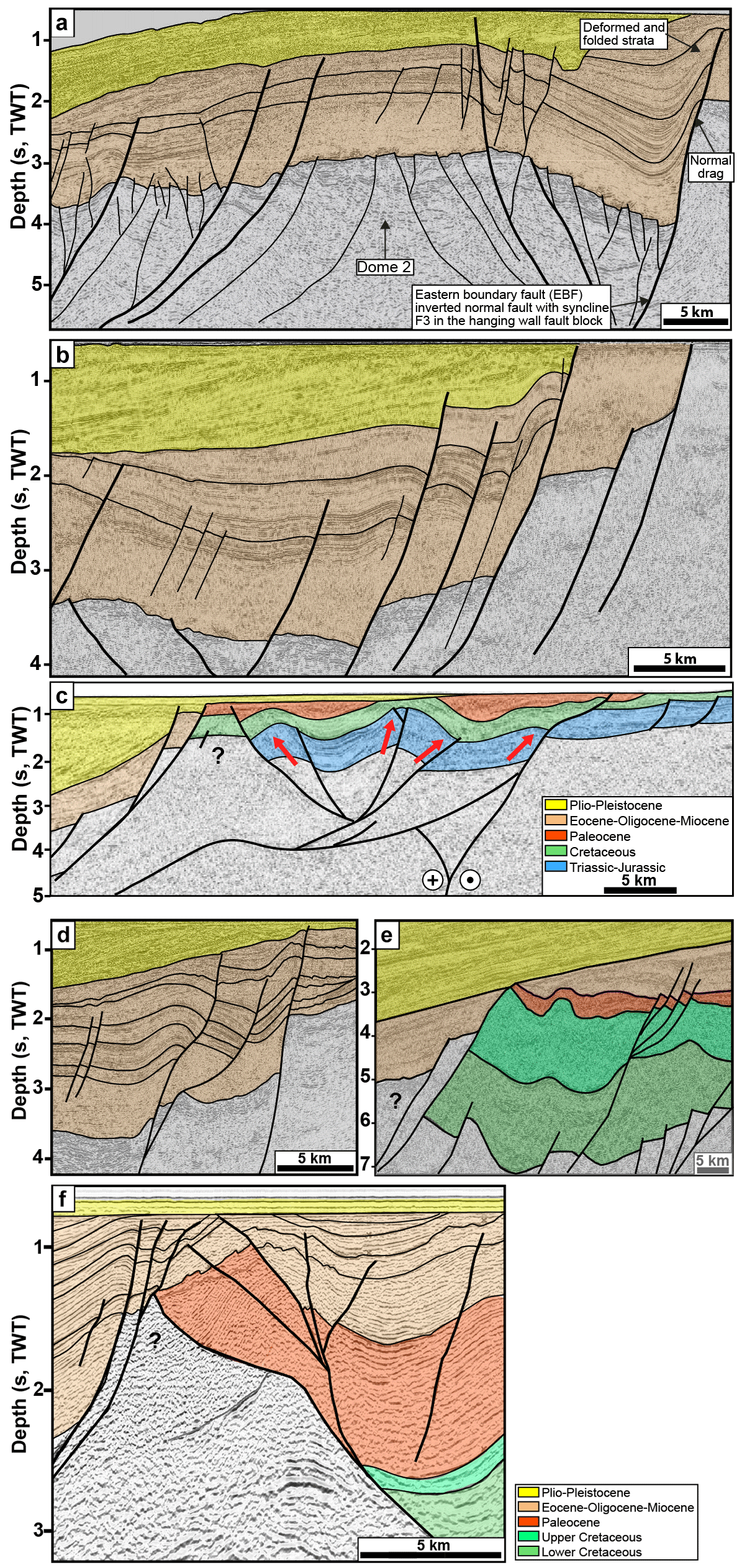
Figure 2Seismic examples from the Vestbakken Volcanic Province. (a) Gentle, partly collapsed, NE–SW-striking anticline and/or dome of uncertain origin in the eastern terrace domain of the southern Vestbakken Volcanic Province. (b, c) Asymmetrical folds (fold family 2; Giannenas, 2018) situated along the eastern margin of the Vestbakken Volcanic Province. These may represent primary SPE-4 structures focused in the hanging walls along margins of master fault blocks, representing reactivated SPE-2 structures. (d) Trains of symmetrical folds with upright fold axes (corresponding to PSE-5 structures) are preserved inside larger fault blocks. See the text for an explanation of SPE structures. (e) Section through a push-up associated with restraining bend (PSE-4 structure). (f) Flower (PSE-2) structure in the area dominated by neutral shear.
In the following sections we provide definitions and a short description of the main structural elements constituting the study area. The structural elements are presented in sequence from north to south (Fig. 1b).
The greater Barents Shear Margin is a part of the more extensive de Geer zone mega shear system which linked the Norwegian–Greenland Sea and the Arctic Eurasia system (Eldholm et al., 1987, 2002; Faleide et al., 1988; Breivik et al., 1998, 2003). Together with its conjugate Greenland counterpart it carries evidence of post-Caledonian extension that culminated with Cenozoic break-up of the North Atlantic (e.g. Brekke, 2000; Gabrielsen et al., 1990; Faleide et al., 1993; Gudlaugsson et al., 1998). Two shear margin segments are separated by a central rift-dominated segment along the Barents Shear Margin (Myhre et al., 1982; Vågnes, 1997; Myhre and Eldholm, 1988; Ryseth et al., 2003; Faleide at al., 1988, 1993, 2008). Each segment maintained the structural and magmatic characteristics of the crust during its development. Of these the Senja Shear Margin is the southernmost segment, originally termed the Senja Fracture Zone by Eldholm et al. (1987). Here NNW–SSE-striking folds interfere with NE–SW-striking structures (Giannenas, 2018). Strain partitioning characterizes the shear zone system (e.g. western Spitsbergen, Leever et al., 2011a, b; the Sørvestsnaget Basin, Kristensen et al., 2017).
The Hornsund Fault Zone and western Spitsbergen fold-and-thrust belt form the northernmost segment of the Barents Shear Margin. It coincides with the southern continuation of the de Geer zone and the Senja Shear Margin. The Hornsund Fault Zone belongs to this system and provides a type setting for transpression and strain partitioning together with the western Spitsbergen fold-and-thrust belt (Harland, 1965, 1969, 1971; Lowell, 1972; Gabrielsen et al., 1990; Maher et al., 1997; Leever et al., 2011 a, b). Plate tectonic reconstructions suggest that the plate boundary accommodated ca. 750 km along-strike dextral displacement and 20–40 km of shortening in the Eocene (Bergh et al., 1997; Gaina et al., 2009).
The Knølegga Fault Zone can be seen as a part of the Hornsund Fault system extending from the southern tip of Spitsbergen (Gabrielsen et al., 1990). It trends NNE–SSW to N–S and defines the western margin of the Stappen High. The vertical displacement approaches 6 km. Although the main movements along the fault may be Tertiary in age, it is likely that it was initiated much earlier. The Tertiary displacement may have a lateral (dextral) component (Gabrielsen et al., 1990).
The Vestbakken Volcanic Province is the main topic of this contribution. It represents the central rifted segment of the Barents Shear Margin and links the sheared margin segments to the north and south, occupying a right double-stepping (eastward) releasing bend setting. Prominent volcanoes and sill intrusions suggest three distinct volcanic events in the Vestbakken Volcanic Province (Jebsen and Faleide, 1998; Faleide et al., 2008; Libak et al., 2012). It is constrained to its east by the eastern boundary fault (EBF in Fig. 1b), which is part of the Knølegga Fault Complex, separating the Vestbakken Volcanic Province from the marginal Stappen High to the east. To the south and southeast the Vestbakken Volcanic Province drops gradually towards the Sørvestsnaget Basin across the southern extension of the eastern boundary fault and its associated faults. To the west and north the area is delineated by the continent–ocean boundary and/or transition. The Vestbakken Volcanic Province includes both extensional and contractional structures (e.g. Jebsen and Faleide, 1998; Faleide et al., 2008; Blaich et al., 2017). Two main episodes of Cenozoic extensional faulting were identified in the Vestbakken Volcanic Province: (i) a late Paleocene–early Eocene event, which correlates in time with the continental break-up in the Norwegian–Greenland Sea, and (ii) an early Oligocene event that is tentatively correlated with plate reorganization around 34 Ma activating NE–SW-striking faults. Volcanic activity coincides with these events.
The Sørvestsnaget Basin occupies the area east of the COT between 71 and 73∘ N and is characterized by an exceptionally thick Cretaceous–Cenozoic sequence (Gabrielsen et al., 1990). To the west it is delineated by the Senja Shear Margin, and to the northeast it is separated from the Bjørnøya Basin by the southern part of the Knølegga Fault Complex (Faleide et al., 1988). The position of the Senja Ridge coincides with the southeastern border of the Sørvestsnaget Basin (Fig. 1b), whereas the Vestbakken Volcanic Province is situated to its north. An episode of Cretaceous rifting in the Sørvestsnaget Basin climaxed in the Cenomanian–middle Turonian (Breivik et al., 1998), succeeded by Late Cretaceous–Paleocene fast sedimentation (Ryseth et al., 2003). The later stages of the basin formation in particular were strongly influenced by the opening of the North Atlantic (Hanisch, 1984; Brekke and Riis, 1987). Salt diapirism also contributed to the development of this basin (Perez-Garcia et al., 2013).
The Senja Ridge (SR in Fig. 1b) runs parallel to the continental margin and coincides with the western border of the Tromsø Basin. It is characterized by a N–S-trending gravity anomaly which is interpreted as buried mafic–ultramafic intrusions associated with the Seiland Igneous Province (Fichler and Pastore, 2022). The structural development of the Senja Ridge has been associated with shear affiliated with the development of the shear margin (Riis et al., 1986), and though it documented that it was a positive structural element from the mid-Cretaceous to the Pliocene, it may have been activated at an even earlier stage (Gabrielsen et al., 1990).
The Senja Shear Margin was active during the Eocene opening of the Norwegian–Greenland Sea dextral shear, causing splitting off of slivers of continental crust. These slivers became embedded in the oceanic crust during continued seafloor spreading (Faleide et al., 2008). The Senja Shear Margin coincides with the western margin of a basin system superimposed on an area of significant crustal thinning. This part of the shear margin was characterized by composite architecture even during the earliest stages of its development (Faleide et al., 2008). The basin system accumulated sedimentary sequences that reached thicknesses of up to 18–20 km. Subsequent shearing contributed to the development of releasing and restraining bends, associated pull-apart basins, neutral strike-slip segments, flower structures, and fold systems (sensu Crowell, 1974a, b; Biddle and Christie-Blick, 1985a, b; Cunningham and Mann, 2007a, b). The hanging wall west of the Knølegga Fault Complex (see below) of the Barents Shear Margin was particularly affected by wrench deformation as seen from several push-ups and fold systems (Grogan et al., 1999; Bergh and Grogan, 2003). The structural development of the margin was complicated by active halokinesis (Knutsen and Larsen, 1997; Gudlaugsson et al., 1998; Ryseth et al., 2003).
The dataset of this study includes 2D seismic reflection data from several surveys and well data from the Vestbakken Volcanic Province. Data coverage is less dense in the northern part of the study area. Typical spacing of seismic lines is 4 km. Well 7316/5-1 was used to correlate the seismic data with formation tops in the study area, while previously published correlations provided the calibration and age of each seismic horizon (e.g. Eidvin et al., 1988, 1993; Ryseth et al., 2003). Three stratigraphic groups are encountered in the well, namely the Nordland Group (between 473–945 m), the Sotbakken Group (between 945–3752 m), and the Nygrunnen Group (between 3752–4014 m) (Eidvin et al., 1993, 1998; https://www.npd.no, last access: 29 August 2023). Several folds of regional significance and with axial traces that can be followed along-strike for 2–3 km or more occur in the Vestbakken Volcanic Province. The folds are commonly situated in the hanging walls of extensional faults, and the fold traces and the structural grain of the thick-skinned master faults are generally parallel. This shows that the position and orientation of the folds were determined by the pre-existing basement structural fabric. The mapping of the folds is constrained by the spacing of refection seismic lines, so each fold trace may include undetected overlap zones or axial offsets. The folds were identified on the lower Eocene, Oligocene, and lower Miocene levels. All the mapped folds are either positioned in the hanging walls of extensional (sometimes inverted) master faults or are dissected by younger faults with minor throws.
Shear margins and strike-slip systems are structurally complex and highly dynamic so that the ultimate architecture of such systems contains structural elements that were not contemporaneous (e.g. Graymer et al., 2007; Crowell, 1962, 1974a, b; Woodcock and Fischer, 1986; Mousloupoulou et al., 2007, 2008). Analogue models offer the option to study the dynamics of such relations; they therefore attracted the attention of early workers in this field (e.g. Cloos, 19281, 1955; Riedel, 1929) and have continued to do so until today. Early experimental works mostly utilized one-layer (“Riedel box”) models (e.g. Emmons, 1969; Tchalenko, 1970; Wilcox et al., 1973), which were soon to be expanded by the study of multilayer systems (e.g. Faugère et al., 1986; Naylor et al., 1986; Richard et al., 1991; Richard and Cobbold, 1989; Schreurs, 1990, 2003; Manduit and Dauteuil, 1996; Dateuil and Mart, 1998; Schreurs and Colletta, 1998, 2003; Ueta et al., 2000; Dooley and Schreurs, 2012). The systematics and dynamics of strike-slip systems have been focused upon in a number of summaries like Sylvester (1985, 1988), Biddle and Christie-Blick (1985a, b), Cunningham and Mann (2007), Dooley and Schreurs (2012), Nemcok et al. (2016), and Peacock et al. (2016). Concepts and nomenclature established in these works are used in the following descriptions and analysis. Also, following Christie-Blick and Biddle (1985a, b) and Dooley and Schreurs (2012) we apply the term principal deformation zone (PDZ) for the junction between the movable polythene plates underlying the experiment. The contact between the fixed and movable base defined a nonstationary velocity discontinuity (VD; Ballard et al., 1987; Allemand and Brun, 1991; Tron and Brun, 1991).
Several experimental works have particularly focused on the geometry and development of pull-apart basins in releasing bend settings (Mann et al., 1983; Faugére et al., 1986; Richard et al., 1991; Dooley and McClay, 1997; Basile and Brun, 1997; Sims et al., 1999; Le Calvez and Vendeville, 2002; Mann, 2007; Mitra and Paul, 2011). The pull-apart basin was described by Burchfiel and Stewart (1966) and Crowell (1974a, b) as formed at a releasing bend or at a releasing fault step-over along a strike-slip zone (Biddle and Christe-Blick, 1985a, b). This basin type has also been termed a “rhomb graben” (Freund, 1971) and “strike-slip basin” (Mann et al., 1983), and it is commonly considered to be synonymous with the extensional strike-slip duplex (Woodcock and Fischer, 1986; Dooley and Schreurs, 2012). In the descriptions of our experiments, we found it convenient to distinguish between extensional strike-slip duplexes in the context of Woodcock and Fischer (1986) or Twiss and Moores (2007, p. 140–141) and pull-apart basins (rhomb grabens: Crowell, 1974a, b; Aydin and Nur, 1993) since they reflect slightly different stages in the development in our experiments (see the Discussion section).
To study the kinematics of complex shear margins, a series of analogue experiments was performed at the tectonic modelling laboratory (TecLab) of Utrecht University, the Netherlands. All experiments were built on two overlapping 1 mm thick plastic sheets (each 100 cm long and 50 cm wide) that were placed on a flat, horizontal table surface. The boundary between the underlying movable and overlying stationary plastic sheets had the shape of the mapped continent–ocean boundary (COB; Fig. 1b). The moveable sheet was connected to an electronic engine, which pulled the sheet at constant velocity during all three deformation stages. Displacement rates were therefore not scaled. The modelling material was then placed on these sheets where the layers on the stationary sheet represent the continental crust including the continent–ocean transition (COT), whereas those on the mobile sheet represent the oceanic crust. The model layers were confined by aluminium bars along the long sides and sand along the short sides (Fig. 3a). The continental crust tapers off towards the oceanic crust with a relatively constant gradient. A sand wedge with a constant dip angle determined by the difference in thickness between the intact and the stretched crust, and that covered the width of the silicon putty layer, was made to simulate the ocean–continent transition (Fig. 3b). The taper angle was kept constant for all models.
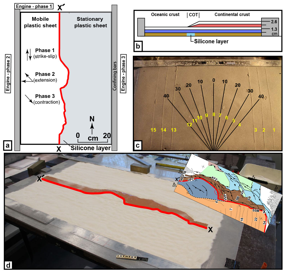
Figure 3(a) Schematical set-up of the BarMar3 experiment as seen in map view. (b) Section through the same experiment before deformation, indicating stratification and thickness relations. (c) Standard positions and orientation for sections cut in all experiments in the BarMar series. Yellow numbers are section numbers. Black numbers indicate the angle between the margins of the experiment (relative to N–S) for each profile. (d) Outline of the silicone putty layer as applied in all experiments. The inset shows the original structural map of the Barents Margin used to define the width of the thinned crust. The red line (X-X') indicates the western limit of the thinned zone.
The precut shape of the plate boundary includes major releasing bends positioned so that they correspond to the geometry of the COB and the three main structural segments of the Barents Shear Margin as follows. Segment 1 of the BarMar experiments (Fig. 4) contained several sub-segments with releasing and restraining bends as well as segments of “neutral” (Wilcox et al., 1973; Mann et al. 1983; Biddle and Christie-Blick, 1985b) or “pure” (Richard et al., 1991) strike-slip. Segment 2 had a basic crescent shape, thereby defining a releasing bend at its southern margin in a position similar to that of the Vestbakken Volcanic Province that merged into a neutral shear segment along the strike, whereas a restraining bend occupied the northern margin of the segment. Segment 3 was a straight basement segment, defining a zone of neutral shear, and corresponds to the strike-slip segment west of Svalbard (Fig. 1).
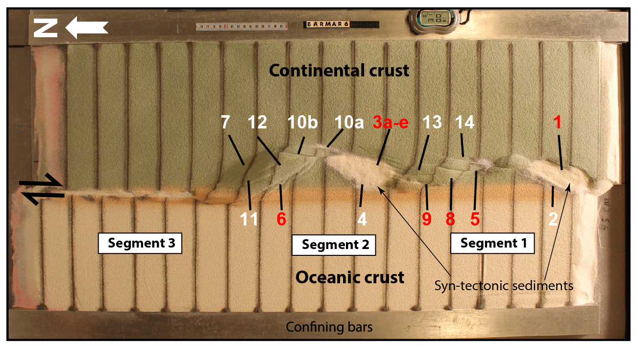
Figure 4Position of segments and major structural elements as referred to in the text and subsequent figures (see particularly Figs. 5 and 6). This example is taken from the reference experiment BarMar6. All experiments (BarMar6–9) followed the same pattern, and the same nomenclature was used in the description of all experiments and provides the template for the definition of structural elements in Fig. 7.
The experiments included three stages of deformation with constant rates of movement of the mobile sheet at 10 cm h−1 in all three stages. The relative angles of plate movements in the experiments were taken from post-late Paleocene opening directions in the northeastern Atlantic (Gaina et al., 2009). Dextral shear was applied in the first phase in all experiments by pulling the lower plastic sheet by 5 cm. In the second phase the left side of the experiment was extended by 3 cm orthogonally (BarMar6) or obliquely (315∘; BarMar8 and 9) to the trend of the shear margin, whereas plate motion was reversed during the third phase of deformation, leading to inversion of earlier formed basins that had been developed in the strike-slip and extensional phases. Sedimentary basins that develop due to strike-slip (phase 1) or extension (phase 2) were filled with layers of coloured feldspar sand by sieving so that a smooth surface was obtained. These layers are primarily important for discriminating among deformation phases and thus act as marker horizons. Phase 3 was initiated by inverting the orthogonal (BarMar6) or oblique (BarMar8 and 9) extension of phase 2 to contraction as a proxy for ridge push that was likely initiated when the mid-oceanic ridge was established in Miocene times in the North Atlantic (Mosar et al., 2002; Gaina et al., 2009). Contraction generated by ridge push has been inferred from the mid-Norwegian continental shelf (Vågnes et al., 1998; Pascal and Gabrielsen, 2001; Faleide et al., 2008; Gac et al., 2016) and seems to still prevail in the northern areas of Scandinavia (Pascal et al., 2005), although far-field compression generated by other processes has been suggested (e.g. Doré and Lundin, 1996).
Coloured layers of dry feldspar sand represent the brittle oceanic and continental crust. This material has proven suitable for simulating brittle deformation conditions (Willingshofer et al., 2005; Luth et al., 2010; Auzemery et al., 2021). It is characterized by a grain size of 100–200 µm, a density of 1300 kg m−3, a cohesion of ∼ 16–45 Pa, and a peak friction coefficient of 0.67 (Willingshofer et al., 2018). Additionally, an 8 mm thick and variable-width silicone putty mixed with fillers corresponding to the transition zone (as mapped in reflection seismic data) of “Rhodorsil Gomme GSIR” (Sokoutis, 1987) was used as a proxy for the thinned and weakened continental crust at the ocean–continent transition (Figs. 1b and 3a, b). This Newtonian material (n=1.09) has a density of 1330 k gm−3 and a viscosity of 1.42 × 10⁴ Pa⋅s.
The experiments were scaled following standard scaling procedures as described by Hubbert (1937), Ramberg (1967), or Weijermars and Schmeling (1986), assuming that inertial forces are negligible when modelling tectonic processes on geologic timescales (see Ramberg, 1981, and Del Ventisette et al., 2007, for a discussion on this topic). The models were scaled so that 10 mm in the model approximates ca. 10 km in nature, yielding a length scale ratio of 1.00 × 10⁻⁶. As such, the model oceanic and continental crusts scale to 18 and 26 km in nature, respectively, which, although slightly overestimating the oceanic crustal thickness (10–12 km), is in full agreement with the estimated thickness of the thinned oceanward segment of the continental crust (30–20 km; Breivik et al., 1998).
The brittle crust made of dry feldspar sand deforms according to the Mohr–Coulomb fracture criterion (Horsfield, 1977; Mandl et al., 1977; McClay, 1990; Richard et al., 1991; Klinkmüller et al., 2016), whereas silicone putty promotes ductile deformation and folding. The configuration applied in the present experiments is accordingly well suited for the study of the COB in the Barents Shear Margin (Breivik et al., 1998).
When complete, the experiments were covered with a thin layer of sand to further stabilize the surface topography before the models were saturated with water and cross-sections that were oriented transverse to the velocity discontinuity were cut in a fan-shaped pattern (Fig. 3c). All experiments have been monitored with a digital camera, providing top-view images at regular time intervals of 1 min.
All experiments performed were oriented in a N–S coordinate framework to facilitate comparison with the western Barents Sea area and had a three-stage deformation sequence (dextral shear, extension, contraction). All descriptions and figures relate to this orientation. It was noted that all experiments reproduced comparable basic geometries and structural types, demonstrating robustness against variations in contrasting strength of the “ocean–continent” transition zone, which included a zone of silicone putty with variable width below an eastward-thickening sand wedge (Fig. 3b). The experiments were terminated before the full closure of the basin system, in accordance with the extension vector > contraction vector as in the North Atlantic (see Vågnes et al., 1998; Pascal and Gabrielsen, 2001; Gaina et al., 2009).
A series of nine experiments (BarMar1–9) with the set-up described above was performed. Experiments BarMar1–5 were used to calibrate and optimize geometrical outline, deformation rate, and angles of relative plate movements and are not shown here. The optimized geometries and experimental conditions were utilized for experiments BarMar6–9, of which BarMar6 and 8 (and some examples from BarMar9) are illustrated here. They yielded similar results in that all crucial structural elements (faults and folds) were reproduced in all experiments as described in the text (Fig. 4). It is emphasized that the extensional basins affiliated with the extension phase (phase 2) were wider for the orthogonal (BarMar6) compared to the oblique extension experiments (BarMar8) (Figs. 5 and 6). Furthermore, the fold systems generated in the experiments that utilized oblique contraction of ∘ (BarMar8–9) produced more extensive systems of non-cylindrical folds. These folds also had continuous but more curved fold traces compared to the experiments with orthogonal extension–contraction (BarMar6). The fold axes generally rotated to become parallel to the (extensional) master faults delineating the pull-apart basins generated in deformation stage 1 in experiments with an oblique opening and closing angle.
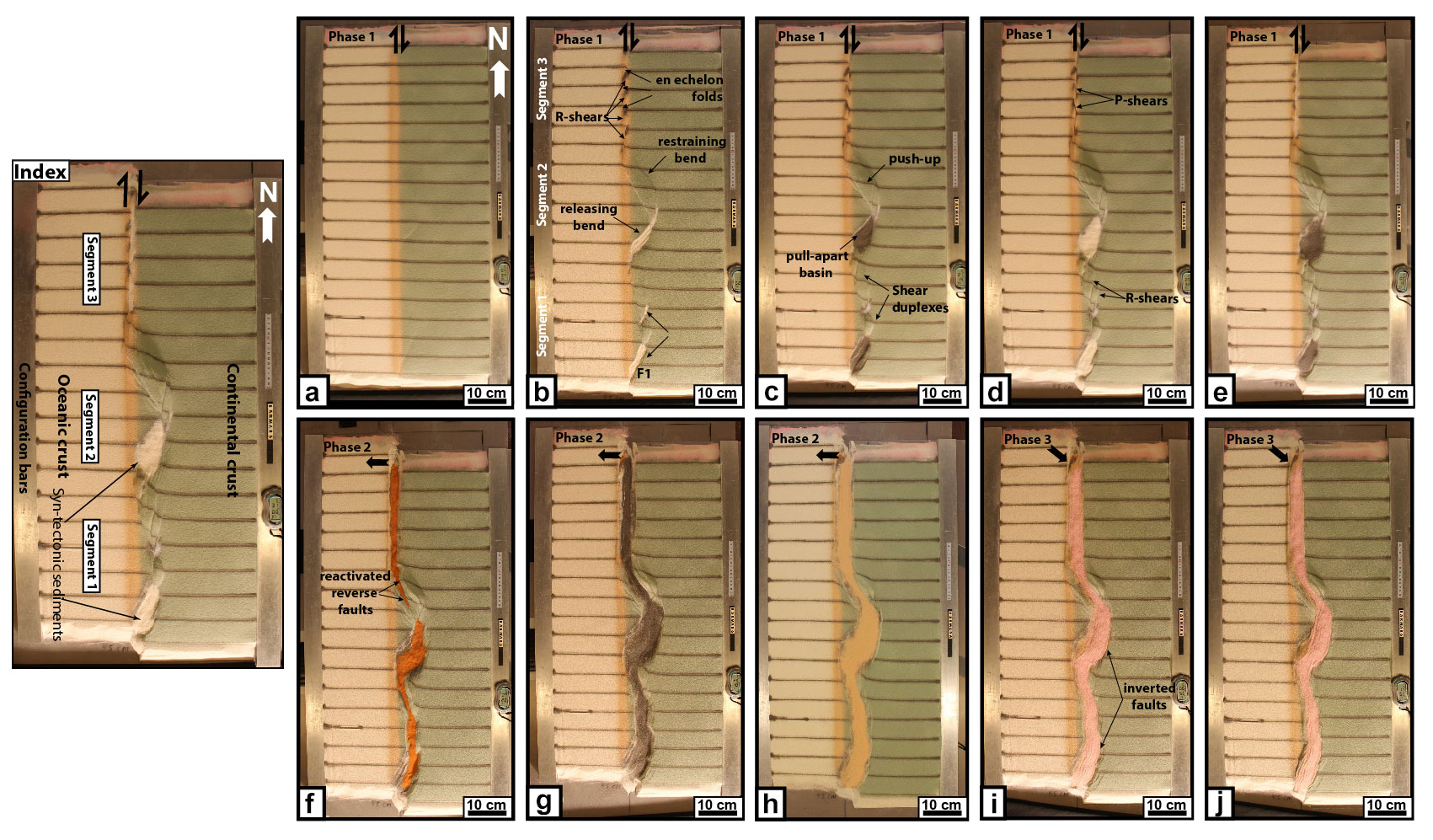
Figure 5Sequential development of experiment BarMar6 by 0.5, 2.4, 3.5, 4.0, and 5.0 cm of dextral shear (steps a–e), orthogonal extension (steps f–h), and oblique contraction (steps i–j). The master fault strands are numbered in Fig. 4, and the sequential development for each structural family is shown in Fig. 7. The reference panel to the upper left shows the positions of the segments.
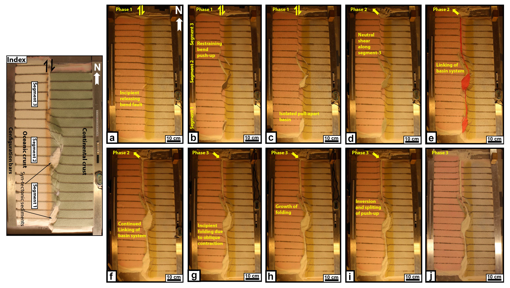
Figure 6Sequential development of experiment BarMar8 by 0.5, 2.4, 3.5, 4.0, and 5.0 cm of dextral shear (steps a–e), oblique extension (steps f–h), and oblique contraction (steps i–h). The master fault strands are numbered in Fig. 3, and the sequential development for each structural family is shown in Fig. 7. Phases 2 and 3 involved oblique (3150) extension and contraction in this experiment. The reference panel to the upper left shows the positions of the segments.
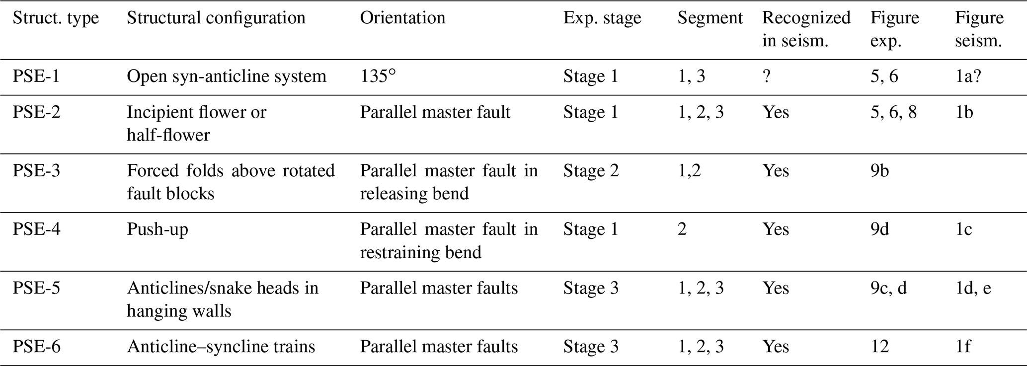
Examples of the sequential development are displayed in Figs. 5 and 6 and summarized in Fig. 7. Elongated positive structural elements with fold-like morphology as seen on the surface were detected during the various stages of the present experiments. The true nature of those was not easily determined until the experiments were terminated and transects could be examined. Such structures included buried push-ups (sensu Dooley and Schreurs, 2012), anti-formal stacks, back-thrusts, positive flower structures, fold trains, and simple anticlines. For convenience, we use the non-genetic term “positive structural elements” (PSEs) for such structure types as seen in the experiments in the following description. In the following the deformation in each segment is characterized for the three deformation phases (Table 1).
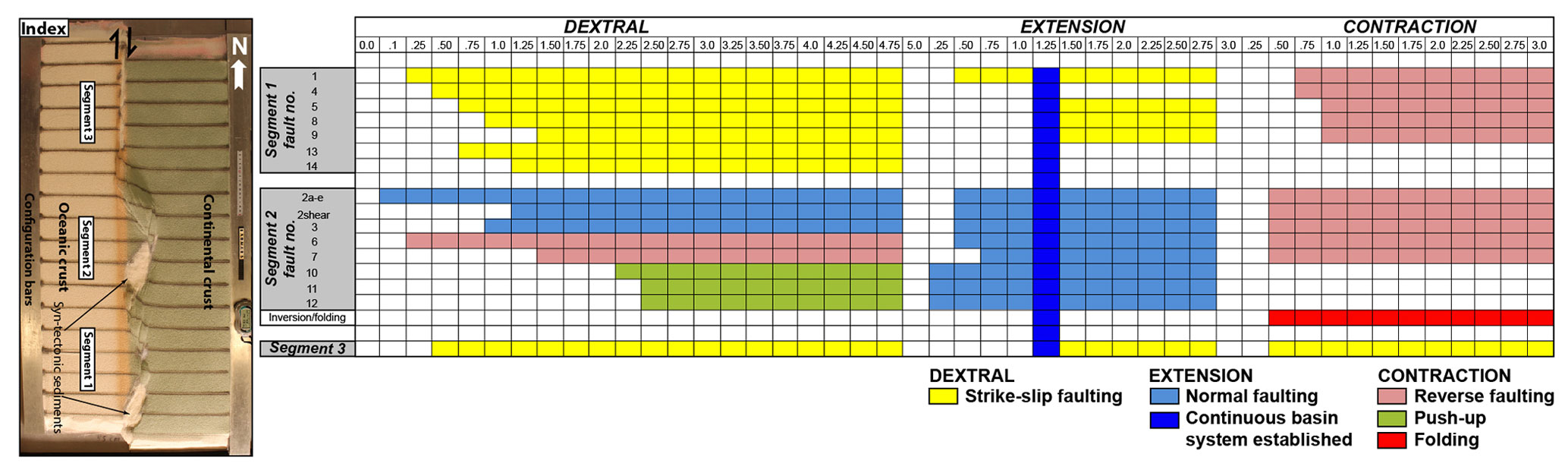
Figure 7Summary of sequential activity in each master fault in experiment BarMar6 (Fig. 5) (for the position of each fault, see Fig. 4). The type and amount of displacement are shown in the two upper horizontal rows. The vertical blue bar indicates the stage at which full along-strike communication became established between marginal basins. The colour code (see inset) indicates the type of displacement at any stage. The reference panel to the left shows the positions of the segments.
Table 1Characteristics of positive structural elements (PSE-1–6) as described in the text and shown in figures. Note that the PSE-1 structures that were developed in the earliest stages of the experiments became cannibalized during the continued deformation. No candidates for these structures were identified in the reflection seismic sections.
6.1 Deformation phase 1: dextral shear stage
In segment 1, differences in the geometry of the precut fault trace between segments 1, 2, and 3 became visible after the first deformation stage. In segments 1 and 3 in particular, an array of oblique en échelon folds between Riedel shear structures (PSE-1 structures) oriented ca. 135∘ (NW–SE) to the regional VD be came visible before rotating towards NNW–SSE by continued shear (Fig. 8; see also Campbell, 1958; Wilcox et al., 1973; Ordonne and Vialon, 1983; Richard et al., 1991; Dooley and Schreurs, 2012). These were simple, harmonic folds with upright axial planes and fold axial traces extending a few centimetres beyond the surface shear zone described above. They had amplitudes on the scale of a few millimetres and wavelengths on the scale of 5 cm. The PSE-1 structures interfered with or were dismembered by younger structures (Y shears and PSE-2 structures; see below), causing northerly rotation of individual intra-fault zone lamellae (remnant PSE-1 structures; Fig. 8). Structures similar to PSE-1 fold arrays are known from almost all strike-slip experiments reported and described in the literature (e.g. Cloos, 1928; Riedel, 1929; see Dooley and Schreurs, 2012, for a summary) and are therefore not given further attention here.
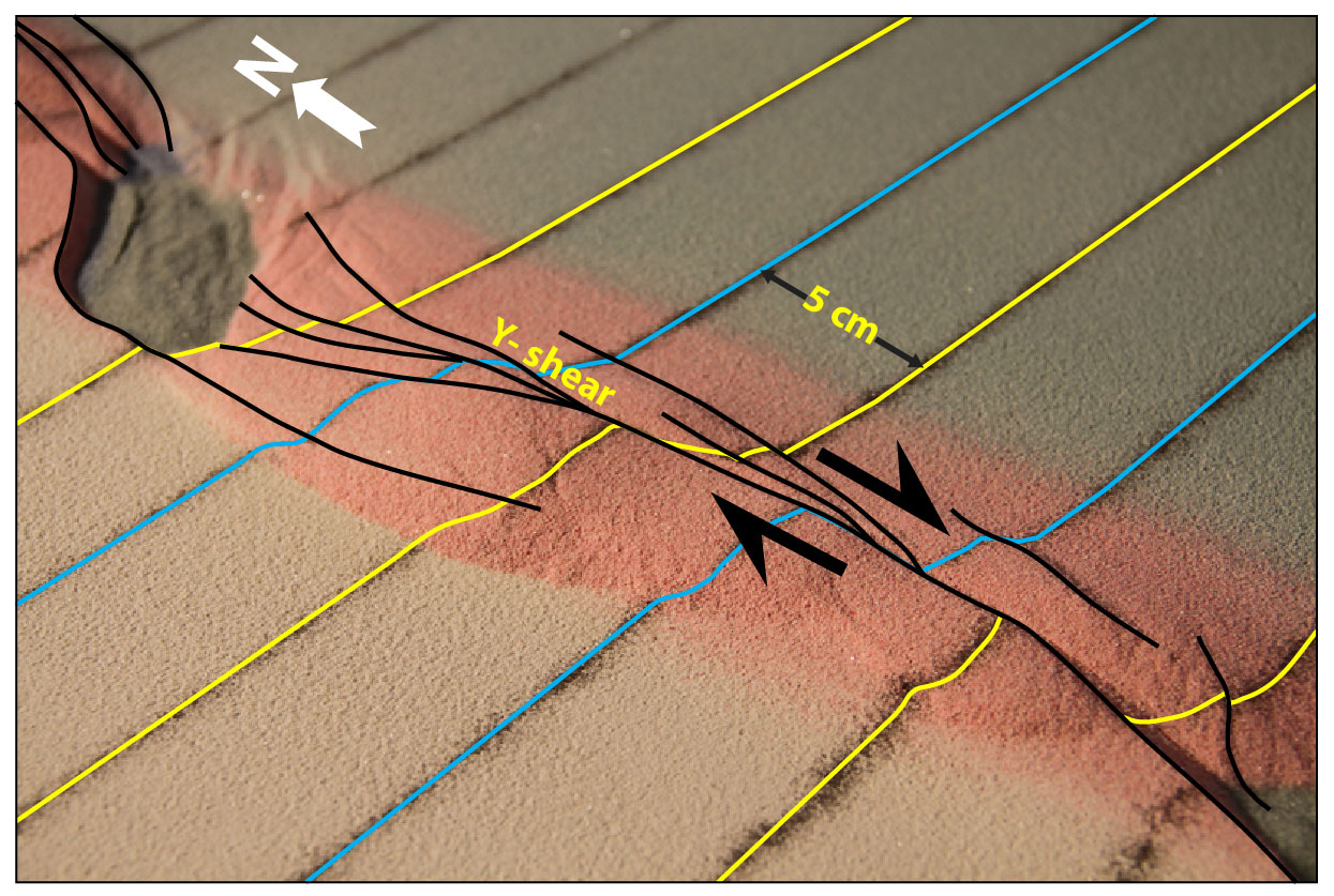
Figure 8PSE-1 anticline–syncline pairs in segment 1 of experiment BarMar6 in an oblique view (see Fig. 4 for the position of segment 1). PSE-1 folds (indicated by relief defined by blue and yellow markers) were constrained to the central fault zone (defined by Y shear and its splay faults) and extended only 3–4 cm beyond it. PSE-2 structures (incipient push-ups and positive flower structures) were delineated by shear faults (black lines) and completely cannibalized PSE-1 structures by continued shear. Yellow and blue reference lines illustrate the rotation of the fold axial trace caused by dextral shear. The pre-shear distance between the markers (blue and yellow lines) was already 5 cm. The black arrow indicates the shear direction.
By 0.25 cm of horizontal displacement in segment 1, which included releasing and restraining bends separated by a central strand of neutral shear, a slightly curvilinear surface trace of a NE–SW-striking, top-NW normal fault in the southernmost part of segment 1 developed. This co-existed with the PSE-1 structures and became paralleled by a normal fault with opposite dip (fault 2, Fig. 4) so that the two faults constrained a crescent- or spindle-shaped incipient extensional shear duplex (Figs. 5b and 6b; see also Mann et al., 1983).
A system of separate en échelon N–S- to NNE–SSE-striking normal and shear fault segments became visible in segment 1 after ca. 1 cm of shear (Fig. 5c, d). These faults did not have the orientations as expected for R (Riedel) and R' (anti-Riedel) shears (that would be oriented with angles of approximately 15 and 75∘ from the master fault trace) but became progressively linked with along-strike growth and the development of new faults and fault segments. They thereby acquired the characteristics of Y shears (oriented sub-parallel to the master fault trace), dissecting the PSE-1 structures. By 2.4 cm of shear, segment 1 had become one unified fault array (Figs. 5d and 6d), delineating a system of incipient push-ups or positive flower structures (PSE-2 structures; Figs. 8 and 10, Sects. B1 and B3).
The PSE-2 structures had amplitudes of 1–2 cm and wavelengths of 3–5 cm as measured on the surface with fault surfaces that steepened downward, with the deepest parts of the structures having cores of sand layers deformed by open to tight folds. The folds had upright or slightly inclined axial planes, dipping up to 55∘, mainly to the east. The structures also affected the shallowest layers down to 1–2 cm in the sequence, but the shallowest sequences developed at a later stage of deformation and were characterized by simple gentle to open anticlines. These structures were constrained to a deformation zone directly above the trace of the basement fault, similar to that commonly seen along shear zones (e.g. Tchalenko, 1971; Crowell, 1974a, b; Dooley and Schreurs, 2012). This zone was 3–4 cm wide, remained stable throughout deformation stage 1, and was restricted to the close vicinity of the basement shear fault itself. A horsetail-like fault array developed by ca. 3 cm of shear at the transitions between segments 1 and 2 (Figs. 5b–d and 6b–d).
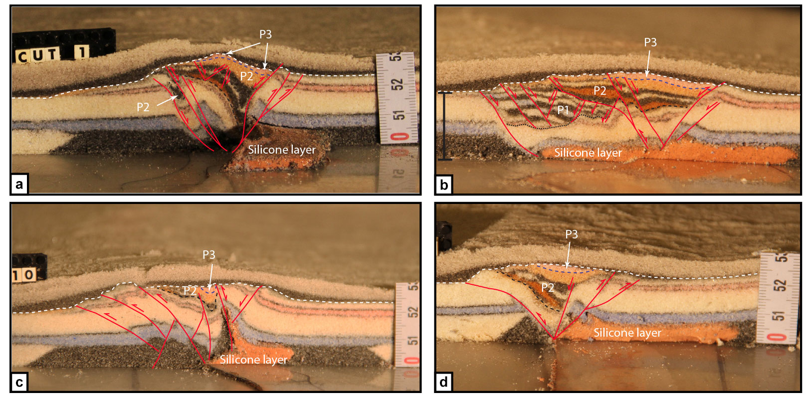
Figure 9Cross-sections through PSE-2-related structures. PSE structures are marked with P and PSE numbers as described in the text (see also Table 1). (a) Folded core of incipient push-up and positive flower structure in segment 1 for experiment BarMar6. The fold structure is completely enveloped by shear faults that have a twisted along-strike geometry. Note that the eastern margin of the structure developed into a negative structure at a late stage in the development (filled by a black–pink sand sequence) and that the silicone putty sequence (basal pink sequence) was entirely isolated in the footwall. (b) Similar structure type in experiment BarMar8. However, the basal silicone putty layer here bridged the basal high-strain zone so that folding occurred in the footwall as well as in the hanging wall. Folds propagated up-section into the sand layers (blue). The folds in upper (pink) layers are younger and were associated with the contractional stage (PSE-6 structures). (c) Contraction associated with the “crocodile structure” in the footwall of the main fault in segment 1 for experiment BarMar8. Note the disharmonic folding with contrasting fold geometries in the hanging wall and footwall as well as at different stratigraphic levels in the footwall, indicating that a shifting stress situation in time and space occurred in the experiment. (d) Transitional fault strand between two more strongly sheared fault segments (experiment BarMar9).
The structuring in segment 2 was determined by the precut crescent-shaped basement fault (velocity discontinuity), which caused the development of a releasing bend along its southern border, and a restraining bend along its northern border (Fig. 11). The first fault of fault array 3a–e in the southern part of segment 2 (Fig. 4) was activated after ca. 0.15 cm of bulk horizontal displacement (Fig. 7). It was situated directly above the southernmost precut releasing bend, defining the margin of crescent-shaped incipient extensional strike-slip duplexes (in the context of Woodcock and Fischer, 1986, Woodcock and Schubert, 1994, and Twiss and Moores, 2007, p. 140–141). The developing basin got a spindle-shaped structure and developed into a basin with a lazy-S shape (Cunningham and Mann, 2007; Mann, 2007). The basin widened towards the east by stepwise footwall collapse, generating sequentially rotating crescent-shaped extensional fault blocks that became trapped as extensional horses in the footwall of the releasing bend (Fig. 11). In the areas of the most pronounced extension the crestal part of the rotational fault blocks became elevated above the basin floor, generating ridges that influenced the basin floor topography and hence the sedimentation. By continued rotation of the fault blocks and simultaneous sieving of sand the crests of the blocks became sequentially uplifted, generating forced folds (Hamblin, 1965; Stearns, 1978; Groshong, 1989; Khalil and McClay, 2017) (Fig. 10a). In the analysis we used the term PSE-3 structures for these features. Simultaneously, an expanding sand sequence became trapped in the footwalls of the master faults, defining typical growth fault geometries.
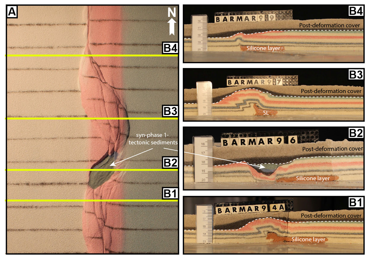
Figure 10(a) Contrasting structural styles along the master fault system in segment 2 in map view and (b) cross-sections of experiment BarMar9. SL denotes the silicone layer; the stippled line is the boundary between pre- and syn-deformation layers, and the dashed white line is the boundary with the post-deformation layers.
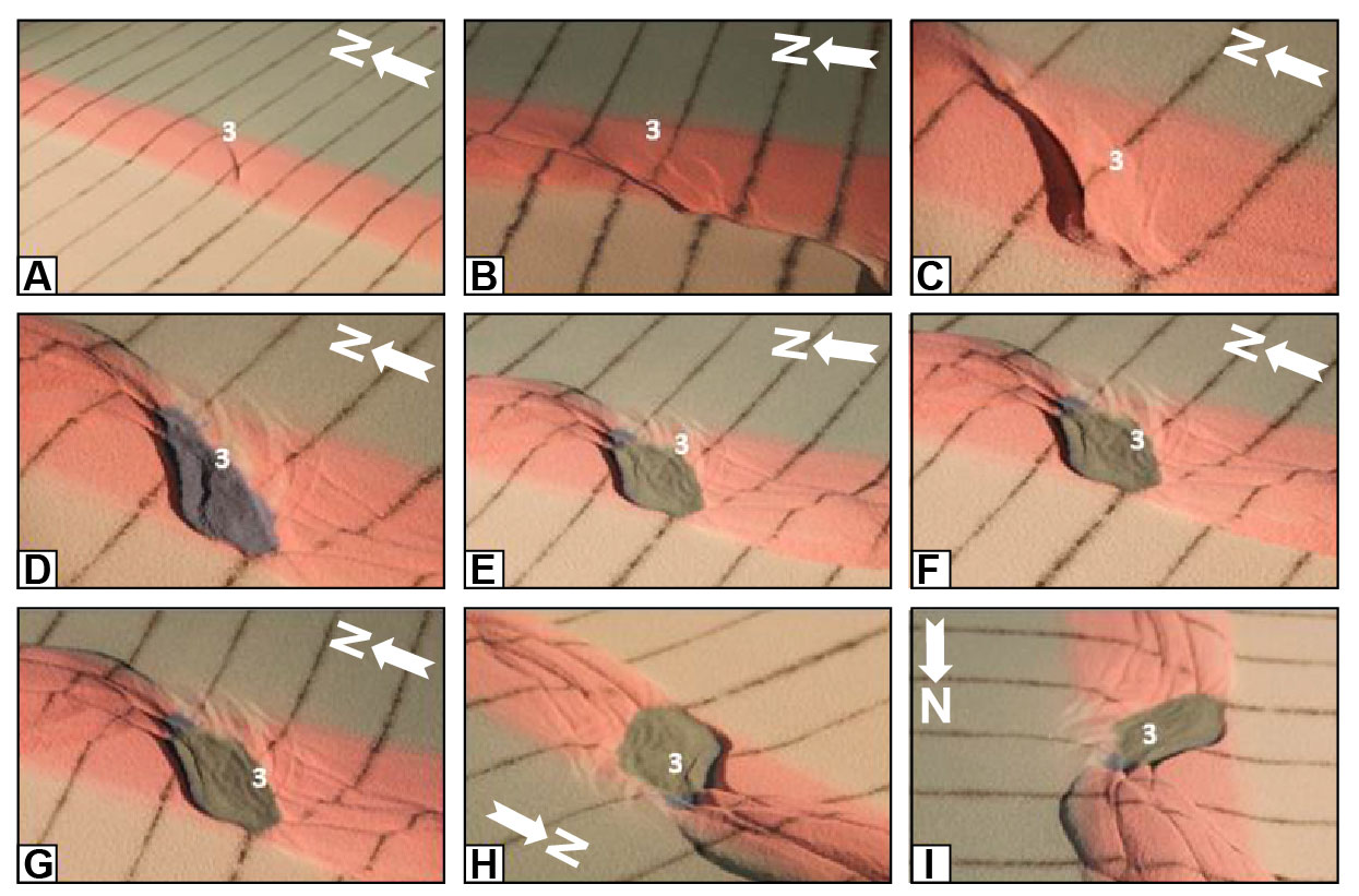
Figure 11Nine stages in the development of the extensional shear duplex system above the releasing bend in experiment BarMar9. The master faults that developed at an incipient stage (e.g. fault 3 that constrained the eastern margin of the extensional shear duplex, marked with a ”3” in the figure; see also Fig. 7) remained stable and continued to be active throughout the experiment but became overstepped by new faults in the footwall. These were reactivated as contraction faults at the later stages (stages h and i in this figure). The developing basement was stabilized by infilling of grey sand during this part of the experiment. Fault 3 continued to breach the basin infill, also after the basin infill overstepped the original basin margin. The distance between the markers (dark lines) is 5 cm. The white arrow marks the north direction. Note that panels (h) and (i) (bottom right) are viewed from different directions than the other panels.
By a shear displacement of 0.55 cm additional curved splay faults were initiated from the northern tip of the master fault of fault 3f (Fig. 7), delineating the northern margin of a rhombohedral pull-apart basin (Mann et al., 1983; Mann, 2007; Christie-Blick and Biddle, 1985) and with a geometry that was indistinguishable from pull-apart basins or rhomb grabens affiliated with unbridged en échelon fault arrays (Crowell, 1974a, b; Aydin and Nur, 1993). Although sand was filled into the subsiding basins to minimize the graben relief and to prevent gravitational collapse, the sub-basins that were initiated in the shear stage were affected by internal cross-faults, and the initial basin units remained the deepest so that the buried internal basin topography maintained a high relief with several apparent depocentres separated by intra-basinal platforms. Systems of linked shear faults and PSE structures became established in the central part with neutral shear that separate the releasing and restraining bends, with development similar to that seen for segment 3 (see below). These structures were, however, soon destroyed by the interaction between the northern and southern tips of the extensional and contractional shear duplexes (Fig. 10).
The first structure to develop in the regime of the restraining bend (segment 2) was a top-to-the-southwest (antithetic) thrust fault at an angle of 135∘ with the regional trend of the basement border as defined by segments 1 and 3 (fault 6). It became visible by 0.5 cm of displacement. However, the northern part of segment 2 became dominated by a synthetic contractional top-to-the-northeast fault that was initiated by 0.85 cm of shear (fault 7; Figs. 5 and 6). Thus, faults 6 and 7 delineated a growing half-crescent-shaped 5–7 cm wide push-up structure (Aydin and Nur, 1982; Mann et al., 1983) south of the restraining bend (Fig. 9; PSE-4 structures). Continued shearing gave these structures the characteristics of an anti-formal stack.
Segment 3 defined a straight strand of neutral shear. Its development in the BarMar experiments strictly followed that known from numerous published experiments (e.g. Tchalenko, 1970; Wilcox et al., 1973; Harding, 1974; Harding and Lowell, 1979; Naylor et al., 1986; Sylvester, 1988; Richard et al., 1991; Woodcock and Schubert, 1994; Dauteuil and Mart, 1998; Mann, 2007; Casas et al., 2001; Dooley and Schreurs, 2012). A train of Riedel shears, occupying the full length of the segment, appeared simultaneously on the surface after a shear displacement of 0.5 cm, occupying a restricted zone with a width of 2–3 cm. The Riedel shears dominated the continued structural development of segment 3. Riedel shears were absent throughout the experiments, as should be expected for a sand-dominated sequence (Dooley and Schreurs, 2012). P shears developed via continued shear, creating linked rhombic structures delineated by the Riedel and P shears generating positive structural elements with NW–SE- and NNE–SSE-striking axes (see also Morgenstern and Tchalenko, 1967), soon coalescing to form Y shears. Transverse sections document the fact that these structures were cored by push-up anticlines, positive half-flower structures, and full-fledged positive flower structures in the advanced stages of shear (PSE-4 structures) (Figs. 5 and 6; see also Fig. 10). These were accompanied by the development of en échelon folds and flower structures as commonly reported from strike-slip faults in nature and in experiments. The width of the zone above the basal fault remained almost constant throughout the experiments but was somewhat wider in experiments with thicker basal silicone polymer layers, similar to what is commonly described from comparable experiments (e.g. Richard et al., 1991).
6.2 Deformation phase 2: extension
The late Cretaceous–Paleocene dextral shear was followed by pure extension that accompanied the opening along the Barents Shear Margin in the Oligocene. Our experiments focused on the effects of oblique extension, acknowledging that plate tectonic reconstructions of the North Atlantic suggest an extension angle of 315∘ (Gaina et al., 2009).
All strike-slip basins widened in the extensional stage, and as one would expect, the basins generated in orthogonal extension became wider than those generated in oblique extension. In both cases, however, extension promoted enhanced relief that had been generated in the shear stage. In the earliest extensional stage, the strike-slip basin in segment 2 dominated the basin configuration. By continued extension the linear segments and the minor pull-apart basins in segments 1 and 2 started to open and became interlinked, subsequently generating a linked basin system that runs parallel to the entire shear margin (Figs. 5f–g, 6f–g). The basins had become completely interlinked by an extension of 1.25 cm (marked by the vertical dark blue line in Fig. 7). The orthogonal extension phase also reactivated and linked several master faults that were established in deformation phase 1 (Figs. 5a and 6a). This became evident by an extension of 0.25–0.50 cm and included the southern fault margin, the push-up, and the splay faults defining the crestal collapse graben (faults 6, 11, and 12; Fig. 4). Among the faults that remained inactive throughout the extension phase was the antithetic contractional fault delineating the push-ups in segment 2 (fault 6; Fig. 4). The Y shear in segment 3 was reactivated as a straight, continuous extensional fault in phase 2. Total extension in stage 2 was 5 cm.
6.3 Deformation phase 3: contraction
In our experiments the extension stage was followed by oblique contraction (parallel to the direction of extension as applied for each experiment). Some of the early-stage contraction was accommodated along new faults. More commonly, however, faults that had been generated in the strike-slip and extensional stages became reactivated and rotated. So was the development of isolated folds, which were commonly associated with inverted fault traces, generating snake-head or harpoon structures (Cooper et al., 1989; Coward, 1994; Allmendinger, 1998; Yameda and McClay, 2004; Pace and Calamitra, 2014; PSE-5 structures). The predominant structures affiliated with the contractional stage were still new folds with traces oriented orthogonal to the shortening direction and sub-parallel to the pre-existing master fault systems that defined the margin and basin margins (Fig. 12). Also, some deep fold sets that had been generated during the strike-slip phase and seen as domal surface features became reactivated, causing renewed growth of surface structures (see Fig. 10 and the explanation in figure caption). These folds were generally upright cylindrical buckle folds in the initial contraction with a very large trace-to-amplitude ratio (SPE-6 structures). Some intra-basin folds, however, defined fold arrays that crossed the basins in a diagonal fashion. Particularly the folds situated along the basin margins developed into fault propagation folds above low-angle thrust planes. Such faults aligning the western basin margins could have an antithetic attitude relative to the direction of contraction.
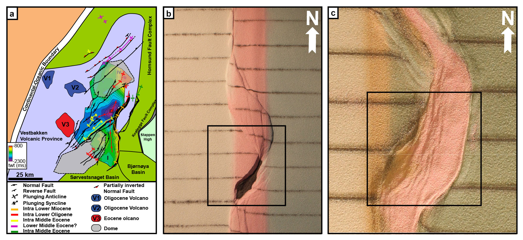
Figure 12PSE-5 folds generated during phase 3 inversion for experiment BarMar8. Note that fold axes are mainly parallel to the basin rims but that they deviate in some cases in the central parts of the basins. The folds are best developed in segment 2, which accumulated extension in the combined shear and extension stages.
During the contractional phase the margin-parallel, linked basin system immediately started to narrow, and several fault strands became inverted. The basin closure was a continuous process until the end of the experiment by 3 cm of contraction. The contraction was initiated as a proxy for an ESE-directed ridge-push stage. The first effect of this deformation stage was heralded by uplift of the margin of the established shear zone that had developed into a rift during deformation stage 2. This was followed by the reactivation and inversion of some master faults (e.g. fault a2; Fig. 4) and thereafter by the development of a new set of low-angle top-to-the-ESE contractional faults. These faults displayed a sequential development (fault family 1; Fig. 7) and were associated with folding of the strata in the rift structure, probably reflecting foreland-directed in-sequence thrusting (SPE-5 and PSE-6 fold populations).
The break-up and subsequent opening of the Norwegian–Greenland Sea constitute a multi-stage event (Fig. 13) that imposed shifting stress configurations overprinting the already geometrically complex Barents Shear Margin. Therefore, scaled experiments were designed to illuminate its structural development. The experiments utilized three main segments that correspond to the Senja Fracture Zone (segment 1), the Vestbakken Volcanic Province (segment 2), and the Hornsund Fault Zone (segment 3) and three deformation phases (dextral shear, oblique extension, and contraction). Several structural families (PSE-1–6) generated in the experiments correspond to structural features observed in reflection seismic sections. In the following discussion we utilize these two datasets in explaining the sequential development of each segment of the shear margin.
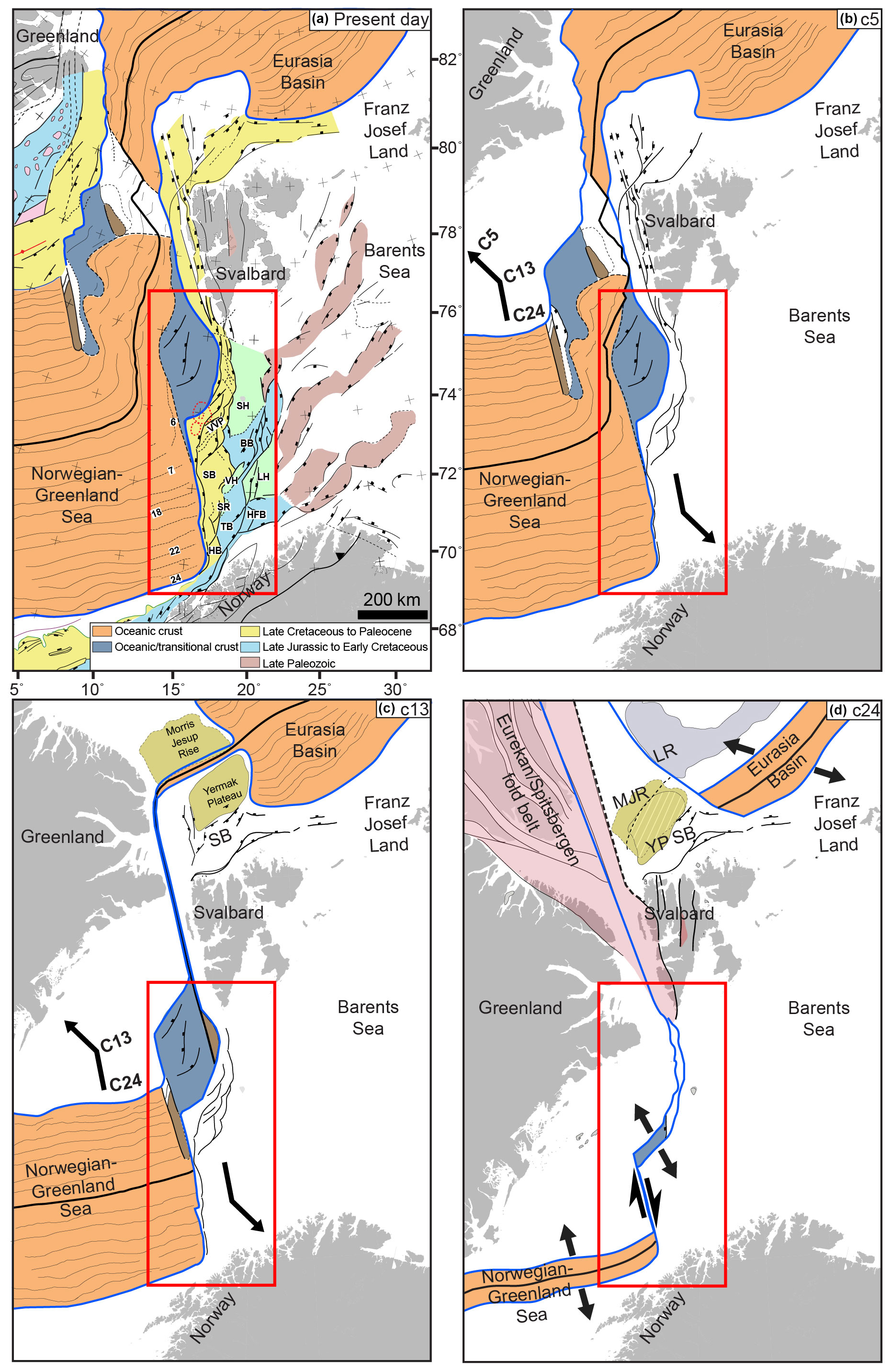
Figure 13Main stages in opening of the North Atlantic. The figure builds on Fig. 5 in Faleide et al. (2008) and has been updated and redrawn.
7.1 Structures of phase 1 (dextral shear)
Segment 1 (corresponding to the Senja Fracture Zone) was dominated by neutral dextral shear, although jogs in the (precut) fault provided minor sub-segments with subordinate releasing and restraining bends. PSE-1 folds seen in the incipient shear phase were confined to the area just above the basal master fault (VD) and its immediate vicinity (see also experiments in series “e” and “f” of Mitra and Paul, 2011). Counterparts to the PSE-1 structural population were not identified in the seismic data, although some isolated, local anticlinal features could be dismembered remnants of such. Because of their constriction to the near vicinity of the master fault it is reasonable that structures generated at an early stage of shear are vulnerable to cannibalization by younger structures with axes striking parallel to the main shear fault (Y shears; SPE-2 structures). We therefore conclude that this structure population was destroyed during the later stages of shear and during the subsequent stages of extension and contraction. PSE-1 folds that developed at an incipient stage were immediately followed by the development of two sets of NNE–SSW-striking normal faults with opposite throws in the releasing bend areas (e.g. fault 2, Fig. 4). The two faults defined crescent- or spindle-shaped incipient extensional shear duplexes. These structures were stable during the remainder of the experiments, and their master faults became reactivated during the extensional and contractional phases (see below). The most prominent of these structures corresponds to the position of the Sørvestsnaget Basin (Fig. 1b).
Segment 2, which was controlled by a precut crescent-shaped discontinuity in the experiments, corresponds to the Vestbakken Volcanic Province and the southern extension of the Knølegga Fault Complex of the Barents Shear Margin (Figs. 1b and 4). The Vestbakken Volcanic Province is dominated by interfering NNW–SSE- and NE–SW-striking fold-and-fault systems in its central part, whereas N–S structures are more common along its eastern margin (Fig. 12a) (Jebsen and Faleide, 1998; Giannenas, 2018). Intra-basinal highs and other internal configurations seen in the BarMar experiments mainly reflect stepwise collapse of the intrinsic basin that generated rotational fault blocks, the crests of which separated local sediment accumulations.
Such structures are common in strike-slip basins (e.g. Dooley and McClay, 1997; Dooley and Schreurs, 2012) and are consistent with the intra-basin depocentres seen within the Vestbakken Volcanic province and in the Sørvestsnaget Basin (Knutsen and Larsen, 1997; Jebsen and Faleide, 1998; Fig. 13). The crests of the rotating fault blocks are termed PSE-3 structures above, and such eroded fault block crests define the footwalls of major faults in the Vestbakken Volcanic Province, providing space for sediment accumulation in the footwalls. The area that was affected by the basin formation in the extensional shear duplex stage seems to have remained the deepest part of the Vestbakken Volcanic Province. The part formed by basin widening through sequential footwall collapse formed a shallower sub-platform (sensu Gabrielsen, 1986) (Fig. 11).
The Knølegga Fault Complex occupies a kilometre-wide zone in segment 2. The master fault strand is paralleled by faults with significant normal throws in its hanging wall side and is part of the larger Knølegga Fault Complex (EBF, eastern boundary fault; Giannenas, 2018; Fig. 12a). The EBF zone is a top-west normal fault with maximum throw of nearly 3000 m. It can be followed along its strike for more than 60 km and seems to die out by horse-tailing at its tip points. The areas around the master faults of the Knølegga Fault Complex locally display isolated elongate positive structures constrained by steeply dipping faults. These structures sometimes display internal reflection patterns that seem exotic in comparison to the surrounding sequences. Some of these structures resemble positive flower structures or push-ups or define narrow anticlines. They are located in both the footwall and hanging wall of the boundary faults and strike parallel to them, and the axes of these structures are parallel to the master faults. The traces of such structures can be followed over shorter distances than the master faults and do not occur in the central parts of the Vestbakken Volcanic Province. We suggest that the composite geometry of the Knølegga Fault Complex is due to the development of PSE-2 structures within the realm of a pre-existing normal fault zone.
Due to the right-stepping geometry during dextral shear in segment 2, the southern and northern parts were in the releasing and restraining bend positions, respectively (e.g. Christie-Blick and Biddle, 1985). Hence, the southern part of segment 2 was subject to oblique extension, subsidence, and basin formation, while the northern part was subject to oblique contraction, shortening, and uplift. The southern segment expanded to the east and northeast by footwall collapse and activation of rotating fault blocks that contributed to a basin floor topography that affected the pattern of sediment accumulation (Fig. 9a, b).
The positive structural elements that prevail in segment 3 belong to the PSE-2 structure population. The structures affiliated with segment 3 in the BarMar experiments are similar to those seen in the reflection seismic sections along parts of the Spitsbergen and the Senja shear margins (Myhre et al., 1982) as well as elsewhere (Cloos, 1928; Riedel, 1929; Tchalenko, 1970; Wilcox et al., 1973). In the experiments én echelon folds (corresponding to PSE-1 structures) first became visible, to be succeeded by the development of Riedel and P shears (R' shears were subdued as expected for sand-dominated sequences; Dooley and Schreurs, 2012). Continued shear followed by collapse and interaction between Riedel and P shears as well as the subsequent development of Y shears initiated a push-up and flower structure with N–S axis (PSE-2) structures that were expressed as non-cylindrical (double-plunging) anticlines on the surface (e.g. Tchalenko, 1970; Naylor et al., 1986). Structures similar to the PSE-2 structures that were initiated in the present experiments are common in scaled experiments with mechanically stratified sequences where viscous basal strata are covered by sand (e.g. Richard et al., 1991; Dauteuil and Mart, 1998).
7.2 Structures of phase 2 (extension)
It is expected that (regional) basin subsidence and (local) fault block subsidence became accelerated during phase 2 (extension), more so in the orthogonal extension experiments (BarMar6) than in the experiments with oblique extension (BarMar8). However, due to stabilization of basins by infilling of sand, this was not documented in the final photographs. The widening occurred mainly by fault-controlled collapse of the footwalls and dominantly along the master faults that correspond to the Knølegga Fault Complex. However, new transverse faults within the basin that had developed during the shear stage (see above) were also reactivated and contributed to the complexity of the basin topography. It is unlikely that a stage was reached where all (pull-apart) basin units along the margin became fully linked, although sedimentary communication along the margin may have occurred.
During the oblique extension stage segment 1 of experiments BarMar7–9 the basin subsidence was focused in the minor pull-apart basins, which soon became linked along the regional N–S-striking basin axis. Remains of several such basin centres, of which the Sørvestsnaget Basin (Knutsen and Larsen, 1997; Kristiansen et al., 2017) is the largest, are preserved and found in seismic data (Fig. 1b). During the experiments a continuous basin system developed in the hanging wall side of the master fault. It is, however, not likely that linking of shear basins occurred prior to the opening stage along the Barents Shear Margin.
7.3 Structures of phase 3 (contraction)
The contraction phase (phase 3) reactivated both normal and shear faults in the master fault zone, also causing folding in the hanging wall. Simultaneously, rotation of (intra-basinal) fault blocks and steepening of pre-existing faults occurred. New fold populations (PSE-5 folds) with axial traces parallel to the basin axis and the master faults characterized the inversion stage. Remnants of such folds are locally preserved in the thickest sedimentary sequences affiliated with the Senja Shear Margin.
Fold systems with fold axes paralleling the basin margins as seen in the experiments are also common in the Vestbakken Volcanic Province. Although shortening occurred inside individual reactivated fault blocks via large-wavelength bulging of the entire sedimentary sequence, trains of folds with larger amplitude and shorter wavelength also developed at this stage (Fig. 12b, c). Thus, the tectonic inversion was focused along the N–S-striking basin margins but also occurred along some pre-existing NE–SW-striking faults and in the central parts of the basin.
During phase 3 the restraining bend configuration in the northern part of segment 2 was characterized by increasing contraction across strike-slip fault strands that splayed out to the northwest from the central part of segment 2 in an early stage of dextral shear. This deformation was terminated by the end of phase 1 by stacking of oblique contraction faults (PSE-5 and PSE-6 structures), defining an anti-formal stack-like structure. This type of deformation falls outside the mapped area, but to the north this type of oblique shortening during the Eocene (phase 1) was accommodated by regional-scale strain partitioning (Leever et al., 2011a, b).
Also, the Vestbakken Volcanic Province is characterized by extensive regional shortening. The onset of this event of inversion–contraction is dated to the early Miocene (Jebsen and Faleide, 1998, Giannenas, 2018), and this deformation included two main structural fold styles. The first includes upright to steeply inclined, closed to open anticlines that are typically present in the hanging wall of master faults. These folds typically have wavelengths of the order of 2.5 to 4.5 km and amplitudes of several hundred metres. Most commonly they appear with head-on snake-head structures and are interpreted as buckle folds, although a component of shear may occur in the areas of the most intense deformation. The second style includes gentle to open anticline–syncline pairs with upright or steep to inclined axial planes with wavelengths on the order of 5 to 7 km and amplitudes of several tens of metres to several hundred metres. We associate those with the PSE-4-type structures as defined in the BarMar experiments. These folds are situated in positions where sedimentary sequences have been pushed against buttresses provided by master faults along the basin margins. The PSE-6 folds developed as fold trains in the interior basins, where buttressing against larger fault walls was uncommon. Also, this pattern fits well with the development and geometry seen in the BarMar experiments, where folding started in the central parts of the closing basins before folding of the marginal parts of the basin. In the closing stage the folding and inversion of master faults remained focused along the basin margins.
The experiments clearly demonstrated that contraction by buckle folding was the main shortening mechanism of the margin-parallel basin system generated in phase 2 (orthogonal or oblique extension) in all segments. In the Vestbakken Volcanic Province segments of the Knølegga Fault Complex, the EBF and the major intra-basinal faults contain clear evidence of tectonic inversion, whereas this is less pronounced in others. The hanging wall of the EBF is partly affected by fish-hook-type inversion anticlines (Ramsey and Huber, 1987; Griera et al., 2018) (Fig. 2d, e), isolated hanging wall anticlines, or pairs or trains of synclines and anticlines (e.g. Roberts, 1989; Coward et al., 1991; Cartwright, 1989; Mitra, 1993; Uliana et al., 1995; Beauchamp et al., 1996; Gabrielsen et al. ,1997; Henk and Nemcok, 2008), with the fold style and associated faults probably being influenced by the orientation and steepness of the pre-inversion fault (Williams et al., 1989; Cooper et al., 1989; Cooper and Warren, 2010). Some structures of this type can still be followed for many kilometres, having consistent geometry and attitude. These structures are not much modified by reactivation and are invariably found in the proximal parts of the footwalls of master faults, suggesting that these are inversion structures. They correlate with PSE-5-type structures in the experiments that developed in areas of focused contraction along pre-existing fault scarps during Oligocene inversion.
Trains of folds with smaller amplitudes and higher frequency are sometimes found in fault blocks in the central part of the Vestbakken Volcanic Province (Fig. 12a). Although these structures cannot be dated by seismic stratigraphical methods (on-lap configurations, etc.) we assume that these folds can be correlated with the tight folds generated in the inversion stage in the experiments (PSE-6 structures) and that they are contemporaneous with the PSE-5 structures.
Segment 1 in the experiments, which corresponds to the Senja Shear Margin, displays a structural pattern that is a hybrid between segments 1 and 2: it contains incipient structural elements that were developed in full in segments 2 and 3, with segment 2 being dominated by releasing and restraining bend configurations and segment 3 dominated by neutral shear. Because of internal configurations, the three segments were affected by secondary (oblique) opening and contraction in various fashions. Understanding these differences was facilitated by the comparison of seismic and model data.
7.4 Some considerations about multiphase deformation in shear margins
The Barents Shear Margin is a challenging target for structural analysis because it represents a geometrically complex structural system with a multi-stage history, but also because high-quality (3D) reflection seismic data are limited and many structures and sedimentary systems generated in the earlier tectono-thermal stages have been overprinted and obliterated by younger events. This makes analogue experiments very useful in the analysis, since they offer a template for what kind of structural elements can be expected. By constraining the experimental model according to the outline of the margin geometry and introducing a dynamic stress model consistent with the current understanding of the tectono-sedimentological evolution, we were able to interpret the observations from the reflection seismic data in a new light.
Continental margins are commonly segmented, containing primary or secondary transform elements, and pure strike-slip transforms are relatively rare (e.g. Nemcok et al., 2016). Such margins, however, invariably become affected by extension following break-up and sometimes contraction due to ridge push or far-field stress, perhaps related to plate reorganization. The complexity of shear margins has ignited several conceptual discussions. One such discussion concerns the presence of zones of weakness prior to break-up (e.g. Sibuet and Mascle, 1978; Taylor et al., 2009; Gibson et al., 2013; Basile, 2015). In the case of the Barents Shear Margin the de Geer zone provides such a pre-existing zone of weakness, and this premise was acknowledged when the scaled model was established. The relevance of our model is therefore constrained to cases in which a crustal-scale zone of weakness existed before break-up. Furthermore, in cases with pre-existing zones of weakness, our model shows that the initial architecture of the margin is indeed important, and the detailed geometry and width of the pre-existing weak zone must be mapped and included in the model.
Our observations confirmed that the main segments of the Barents Shear Margin, albeit undergoing the same regional stress regime, display contrasting structural configurations. The deformation in segment 2 in the BarMar experiments was determined by releasing and restraining bends in the southern and northern parts, respectively. Thus, the southern part, corresponding to the Vestbakken Volcanic Province, was dominated by the development of a regional-scale extensional shear duplex as defined by Woodcock and Fischer (1983) and Twiss and Moores (2007). Through continued shear the basin developed into a full-fledged pull-apart basin or rhomb graben (Crowell, 1974; Aydin and Nur, 1982) in which rotating fault blocks were trapped. The pull-apart basin became the nucleus for greater basin systems to develop in the following phase of extension, also providing the space for folds to develop in the contractional phase.
We conclude that fault-and-fold systems found in the realm of the Vestbakken Volcanic Province are in accordance with a three-stage development that includes dextral shear followed by oblique extension and contraction (∘) along a shear margin with composite geometry. Folds with NE–SW-trending fold axes are dominant in wider areas of the Vestbakken Volcanic Province and are dominated by folds in the hanging walls of (older) normal faults, sometimes characterized by narrow snake-head- or harpoon-type structures that are typical for tectonic inversion (Cooper et al., 1989; Coward, 1994; Allmendinger, 1998; Yameda and McClay, 2004; Pace and Calamitra, 2014).
Comparison of seismic mapping and analogue experiments shows that one of the major challenges in analysing the structural pattern in shear margins of complex geometry and multiple reactivation is the low potential for preservation of structures formed in the earliest stages of development.
The 2D seismic data are released and available through DISKOS, the Norwegian National Data Repository for petroleum data: https://www.npd.no/en/diskos/seismic/ (DISKOS, 2021).
RHG: contributions to outline, design and performance of experiments, first writing and revisions of the paper, first drafts of figures. PAG: seismic interpretation in the Vestbakken Volcanic Province, identification and description of fold families. DS: main responsibility for set-up, performance, and handling of experiments; revisions of the paper. EW: performance and handling of experiments, revisions of the paper, design and revisions of figure material. MH: background seismic interpretation, discussions and revisions of the paper, design and revisions of figure material. JIF: regional interpretations and design of experiments, participation in performance and interpretations of experiments, revisions of the paper, design and revisions of figure material.
At least one of the (co-)authors is a guest member of the editorial board of Solid Earth for the special issue “Analogue modelling of basin inversion”. The peer-review process was guided by an independent editor, and the authors also have no other competing interests to declare.
Publisher's note: Copernicus Publications remains neutral with regard to jurisdictional claims in published maps and institutional affiliations.
This article is part of the special issue “Analogue modelling of basin inversion”. It is not associated with a conference.
The work was supported by ARCEx (Research Centre for Arctic Petroleum Exploration), which was funded by the Research Council of Norway (grant no. 228107) together with 10 academic and 6 industry (Equinor, Vår Energi, Aker BP, Lundin Energy Norway, OMV, and Wintershall Dea) partners. Muhammad Hassaan was funded by the Suprabasins project (Research Council of Norway, grant no. 295208). We thank Schlumberger for providing us with academic licenses for Petrel software to do seismic interpretation. Two anonymous reviewers and the editors of this special issue provided comments, suggestions, and advice that enhanced the clarity and scientific quality of the paper.
This research has been supported by Norges Forskingsråd grants ARCEx (Research Council of Norway, grant no. 228107) and Suprabasins (Research Council of Norway, grant no. 295208).
This paper was edited by Federico Rossetti and Michael Rudolf and reviewed by two anonymous referees.
Allemand, P. and Brun, J. P.: Width of continental rifts and rheological layering of the lithosphere, Tectonophysics, 188, 63–69, 1991.
Allmendinger, R. W.: : Inverse and forward numerical modeling of threeshear fault-propagation folds, Tectonics, 17, 640–656, 1998.
Auzemery, A., Willingshofer, E., Sokoutis, D., Brun, J. P., and Cloetingh S. A. P. L.: Passive margin inversion controlled by stability of the mantle lithosphere, Tectonophysics, 817, 229042, https://doi.org/10.1016/j.tecto.2021.229042, 2021.
Aydin, A. and Nur, A.: Evolution of pull-apart basins and their scale independence, Tectonics, 1, 91–105, 1982.
Ballard, J.-F., Brun, J.-P., and Van Ven Driessche, J.: Propagation des chevauchements au-dessus des zones de décollement: modèles expérimentaux, CR Acad. Sci., 11, 305, 1249–1253, 1987.
Basile, C.: Transform continental margins – Part 1: Concepts and models. Tectonophysics, 661, 1–10, https://doi.org/10.1016/j.tecto.2015.08.034, 2015.
Basile, C. and Brun, J.-P.: Transtensional faulting patterns ranging from pull-apart basins to transform continental margins: an experimental investigation, J. Struct. Geol., 21, 23–37, 1997.
Beauchamp, W., Barazangi, M., Demnati, A., and El Alji, M.: Intracontinental rifting and inversion: Missour Basin and Atlas Mountains, Morocco, AAPG Bull., 80, 1455–1482, 1996.
Bergh, S. G. and Grogan, P.: Tertiary structure of the Sørkapp-Hornsund Region, South Spitsbergen, and implications for the offshore southern extension of the fold-thrust-belt, Norw. J. Geol., 83, 43–60, 2003.
Bergh, S. G., Braathen, A. and Andresen, A.: Interaction of basement-involved and thin-skinned tectonism in the Tertiary fold-and-thrust belt of Central Spitsbergen, Svalbard, APPG Bull., 81, 637–661, 1997.
Biddle, K. T. and Christie-Blick, N.: Strike-Slip Deformation, Basin Formation, and Sedimentation, Soc. Econ. Pa., 37, 386 pp., 1985a.
Biddle, K. T. and Christie-Blick, N.: Glossary – Strike-slip deformation, basin formation, and sedimentation, in: Biddle, K.T., and Christie-Blick, N. (eds.): Strike-Slip Deformation, Basin Formation, and Sedimentation, Soc. Econ. Pa., 37, 375–386, 1985b.
Blaich, O. A., Tsikalas, F., and Faleide, J. I.: New insights into the tectono-stratigraphic evolution of the southern Stappen High and the transition to Bjørnøya Basin, SW Barents Sea, Mar. Petrol. Geol., 85, 89–105, https://doi.org/10.1016/j.marpetgeo.2017.04.015, 2017.
Breivik, A. J., Faleide, J. I., and Gudlaugsson, S. T.: Southwestern Barents Sea margin: late Mesozoic sedimentary basins and crustal extension, Tectonophysics, 293, 21–44, 1998.
Breivik, A. J., Mjelde, R., Grogan, P., Shinamura, H., Murai, Y., and Nishimura, Y.: Crustal structure and transform margin development south of Svalbard based on ocean bottom seismometer data, Tectonophysics, 369, 37–70, 2003.
Brekke, H.: The tectonic evolution of the Norwegian Sea continen- tal margin with emphasis on the Vøring and Møre basins, Geol. Soc. Eng. Geol. Sp., 136, 327–378, 2000.
Brekke, H. and Riis, F.: Mesozoic tectonics and basin evolution of the Norwegian Shelf between 60∘ N and 72∘ N, Norsk Geol. Tidsskr., 67, 295–322, 1987.
Burchfiel, B. C. and Stewart, J. H.: “Pull-apart” origin of the central segment of Death Valley, California, Geol. Soc. Am. Bull., 77, 439–442, 1966.
Campbell, J. D.: En échelon folding, Economical Geology, 53, 448–472, 1958.
Cartwright, J. A.: The kinematics of inversion in the Danish Central Graben, in: Inversion Tectonics, edited by: Cooper, M. A. and Williams, G. D., Geol. Soc. Spec. Publ., 44, 153–175, 1989.
Casas, A. M., Gapals, D., Nalpas, T., Besnard, K., and Román-Berdiel, T.: Analogue models of transpressive systems, J. Struct. Geol., 23, 733–743, 2001.
Christie-Blick, N. and Biddle, K. T.: Deformation and basin formation along strike-slip faults, in: Strike-slip deformation, basin formation and sedimentation, edited by: Biddle, K. T. and Christie-Blick, N., Society of Economic Mineralogists and Palaeontologists (Tulsa Oklahoma), Special Publication, 37, 1–34, 1985.
Cloos, H.: Experimenten zur inneren Tectonick, Zentralblatt für Mineralogie, Geologie und Palaentologie, 1928B, 609–621, 1928.
Cloos, H.: Experimental analysis of fracture patterns, Geol. Soc. Am. Bull., 66, 241–256, 1955.
Cooper, M. and Warren, M. J.: The geometric characteristics, genesis and petroleum significance of inversion structures, in: Continental Tectonics and Mountain Building: The Lagacy of Peache and Horne, edited by: Law, R. D., Butler, R. W. H., Holdsworth, R. E., Krabbendam, M., and Strachan, R. A., Geol. Soc. Spec. Publ., 335, 827–846, 2010.
Cooper, M. A., Williams, G. D., de Graciansky, P. C., Murphy, R. W., Needham, T., de Paor, D., Stoneley, R., Todd, S. P., Turner, J. P., and Ziegler, P. A.: Inversion tectonics – a discussion, Geol. Soc. Spec. Publ., 44, 335–347, 1989.
Coward, M.: Inversion tectonics, in: Continental Deformation, edited by: Hancock, P. L., Pergamon Press, 289–304, https://doi.org/10.1017/S0016756800011602, 1994.
Coward, M. P., Gillcrist, R., and Trudgill, B.: Extensional structures and their tectonic inversion in the Western Alps, in: The Geometry of Normal Faults, Roberts, A. M., Yielding, G., and Freeman, B., Geol. Soc. Spec. Publ., 56, 93–112, 1991.
Crowell, J. C.: Displacement along the San Andreas Fault, California, Geol. S. Am. S., 71, 59 pp., 1962.
Crowell, J. C.: Origin of late Cenozoic basins in southern California, in: Modern and ancient geosynclinal sedimentation, edited by: Dorr, R. H. and Shaver, R. H., SEPM Spec. P., 19, 292–303, 1974a.
Crowell, J. C.: Implications of crustal stretching and shortening of coastal Ventura Basin, in: Aspects of the geological history of the Calefornia continental Borderland, edited by: Howell, D. G., AAPG Bull., 24, 365–382, 1974b.
Cunningham, W. D. and Mann, P.: Tectonics of Strike-Slip Restraining and Releasing Bends, Geol. Soc. Spec. Publ., 290, 482 pp., 2007a.
Cunningham, W. D. and Mann, P.: Tectonics of Strike-Slip Restraining and Releasing Bends, in: Tectonics of Strike-Slip Restraining and Releasing Bends, edited by: Cunningham, W. D. and Mann, P., Geol. Soc. Spec. Publ., 290, 1–12, 2007b.
Dauteuil, O. and Mart, Y.: Analogue modeling of faulting pattern, ductile deformation, and vertical motion in strike-slip fault zones, Tectonics, 17, 303–310, 1998.
Del Ventisette, C., Montanari, D., Sani, F., Bonini, M., and Corti, G.: Reply to comment by J. Wickham on “Basin inversion and fault reactivation in laboratory experiments”, J. Struct. Geol., 29, 1417–1418, 2007.
DISKOS: The Norwegian National Data Repository for petroleum data, DISKOS [data set], https://www.npd.no/en/diskos/seismic/ (last access: 25 November 2021), 2021.
Dooley, T. and McClay, K.: Analog modeling of pull-apart basins, Am. Assoc. Petr. Geol. B., 81, 1804–1826, 1997.
Dooley, T. P. and Schreurs, G.: Analogue modelling of intraplate strike-slip tectonics: A review and new experimental results, Tectonophysics, 574–575, 1–71, 2012.
Doré, A. G. and Lundin, E. R.: Cenozoic compressional structures on the NE Atlantic margin: nature, origin and potential significance for hydrocarbon exploration, Petrol. Geosci., 2, 299–311, 1996.
Doré, A. G., Lundin, E. R., Jensen, L. N., Birkeland, Ø., Eliassen, P. E., and Fichler, C.: Principal tectonic events in the evolution of the northwest European Atlantic margin, in: Petroleum Geology of Northwest Europe: Proceedings of the Fifth Conference, edited by: Fleet, A. J. and Boldy, S. A. R., Geological Society of London, 41–61, https://doi.org/10.1144/0050041, 1999.
Doré, A. G., Lundin, E. R., Gibbons, A., Sømme, T. O., and Tørudbakken, B. O.: Transform margins of the Arctic: a synthesis and re-evaluation in: Transform Margins,: Development, Control and Petroleum Systems, edited by: Nemcok, M., Rybár, S., Sinha, S. T., Hermeston, S. A., and Ledvényiová, L., Geol. Soc. Spec. Publ., 431, 63–94, 2016.
Eidvin, T., Goll, R. M., Grogan, P., Smelror, M., and Ulleberg, K.: The Pleistocene to Middle Eocene stratigraphy and geological evolution of the western Barents Sea continental margin ta well site 731675-1 (Bjørnøya West area), Norsk Geol. Tidsskr., 78, 99–123, 1988.
Eidvin, T., Jansen, E., and Riis, F.: Chronology of Tertiary fan deposits off the western Barents Sea: Implications for the uplift and erosion history of the Barents Shelf, Mar. Geol., 112, 109–131, 1993.
Eldholm, O., Faleide, J. I., and Myhre, A. M.: Continent-ocean transition at the western Barents Sea/Svalbard continental margin, Geology, 15, 1118–1122, 1987.
Eldholm, O., Tsikalas, F., and Faleide, J. I.: Continental margin off Norway 62–75∘ N: Paleogene tectono-magmatic segmentation and sedimentation, Geol. Soc. Spec. Publ., 197, 39–68, 2002.
Emmons, R. C.: Strike-slip rupture patterns in sand models, Tectonophysics, 7, 71–87, 1969.
Faleide, J. I., Myhre, A. M., and Eldholm, O.: Early Tertiary volcanism at the western Barents Sea margin, in: Early Tertiary volcanism and the opening of the NE Atlantic, edited by: Morton, A. C. and Parsons, L. M., Geol. Soc. Spec. Publ., 39, 135–146, 1988.
Faleide, J. I., Vågnes, E., and Gudlaugsson, S. T.: Late Mesozoic – Cenozoic evolution of the south-western Barents Sea in a regional rift-shear tectonic setting, Mar. Petrol. Geol., 10, 186–214, 1993.
Faleide, J. I., Tsikalas, F., Breivik, A. J., Mjelde, R., Ritzmann, O., Engen, Ø., Wilson, J., and Eldholm, O.: Structure and evolution of the continental margin off Norway and the Barents Sea, Episodes, 31, 82–91, 2008.
Faleide, J. I., Bjørlykke, K., and Gabrielsen, R. H.: Geology of the Norwegian Shelf, in: Petroleum Geoscience: From Sedimentary Environments to Rock Physics, edited by: Bjørlykke, K., 2nd edn., Springer-Verlag, Berlin Heidelberg, Chap. 25, 603–637, https://doi.org/10.1007/978-3-642-34132-8_25, 2015.
Faugère, E., Brun, J.-P., and Van Den Driessche, J.: Bassins asymmétriques en extension pure et en détachements: Modèles expérimentaux, Bulletin Centre Recherche Exploration et Production Elf Aquitaine, 10, 13–21, 1986.
Fichler, C. and Pastore, Z.: Petrology and crystalline crust in the southwestern Barents Sea inferred from geophysical data, Norw. J. Geol., 102, 1–41, https://doi.org/10.17850/njg102-2-2, 2022.
Freund, R.: The Hope Fault, a strike-slip fault in New Zealand, New Zealand Geological Survey Bulletin, 86, 1–49, 1971.
Gabrielsen, R. H.: Structural elements in graben systems and their influence on hydrocarbon trap types, in: Habitat of Hydrocarbons on the Norwegian Continental Shelf, edited by: Spencer, A. M., Norw. Petrol. Soc., 55–60, 1986.
Gabrielsen, R. H., Færseth, R. B., Jensen, L. N., Kalheim, J. E., and Riis, F.: Structural elements of the Norwegian Continental Shelf. Part I: The Barents Sea Region, Norwegian Petroleum Directorate, Bulletin, 6, 1–33, 1990.
Gabrielsen, R. H., Grunnaleite, I., and Rasmussen, E.: Cretaceous and Tertiary inversion in the Bjørnøyrenna Fault Complex, south-western Barents Sea, Mar. Petrol. Geol., 142, 165–178, 1997.
Gac, S., Klitzke, P., Minakov, A., Faleide, J. I., and Scheck-Wenderoth, M.: Lithospheric strength and eleastic thickness of the Barents Sea and Kara Sea region, Tectonophysics, 691, 120–132, https://doi.org/10.1016/j.tecto.2016.04.028, 2016.
Gaina, C., Gernigon, L., and Ball, P.: Palaeocene – Recent plate boundaries in the NE Atlantic and the formation of the Jan Mayen microcontinent, J. Geol. Soc., London, 166, 601–616, 2009.
Ganerød, M., Smethurst, M. A., Torsvik, T. H., Prestvik, T., Rousse, S., McKenna, C., van Hinsberen, D. J. J., and Hendriks, W. W. H.: The North Atlantic Igneous Province reconstructed and its relation to the Plume Generation Zone: the Antrim Lava Group revisited, Geophys. J. Int., 182, 183–202, https://doi.org/10.1111/j.1365-246X.2010.04620.x, 2010.
Giannenas, P. A.: The Structural Development of the Vestbakken Volcanic Province, Western Barents Sea. Relation between Faults and Folds, unpublished Ms.Sci.thesis, University of Oslo, 89 pp., http://urn.nb.no/URN:NBN:no-66933 (last access: 29 August 2023), 2018.
Gibson, G. M., Totterdell, J. M., White, N., Mitchell, C. H., Stacey, A. R., M. P. Morse, M. P., and Whitaker, A.: Preexisting basement structures and its influence on continental rifting and fracture development along Australia's southern rifted margin, J. Geol. Soc. London, 170, 365–377, 2013.
Graymer, R. W., Langenheim, V. E., Simpson, R. W., Jachens, R. C. and Ponce, D. A.: Relative simple through-going fault planes at large-earthquake depth may be concealed by surface complexity of strike-slip faults, in: Tectonics of Strike-Slip Restraining and Releasing Bends, edited by: Cunningham, W. D. and Mann, P., Geol. Soc. Spec. Publ., 290, 189–201, 2007.
Griera, A., Gomez Rivas, E., and Llorens, M.-G.: The influence of layer-interface geometry of single-layer folding, Geol. Soc. Spec. Publ. 487, 59–79, https://doi.org/10.1144/SP487.4, 2018.
Grogan, P., Østvedt-Ghazi, A.-M., Larssen, G. B., Fotland, B., Nyberg, K., Dahlgren, S., and Eidvin, T.: Structural elements and petroleum geology of the Norwegian sector of the northern Barents sea, in: Petroleum Geology of Northwest Europe: Proceedings of the 5th Conference, edited by: Fleet, A. J. and Boldry, S. A. R., Geological Society of London, 247–259, https://doi.org/10.1144/0050247, 1999.
Groshong, R. H.: Half-graben structures: balanced models of extensional fault bend folds, Geol. Soc. Am. Bull., 101, 96–195, 1989.
Gudlaugsson, S. T., Faleide, J. I., Johansen, S. E., and Breivik, A. J.: Late Palaeozoic structural development of the south-western Barents Sea, Mar. Petrol. Geol., 15, 73–102, 1998.
Hamblin, W. K.: Origin of “reverse drag” on the down-thrown side of normal faults, Geol. Soc. Am. Bull., 76, 1145–1164, 1965.
Hanisch, J.: The Cretaceous opening of the Northeast Atlantic, Tectonophysics, 101, 1–23, 1984.
Harding, T. P.: Petroleum traps associated with wrench faults, AAPG Bull., 58, 1290–1304, 1974.
Harding, T. P. and Lowell, J. D.: Structural styles, their plate tectonic habitats, and hydrocarbon traps in petroleum provinces, AAPG Bull., 63, 1016–1058, 1979.
Harland, W. B.: The tectonic evolution of the Arctic-North Atlantic Region, in: Discussion, A Symposium on Continental Drift, edited by: Taylor, J. H., Rutten, M. G., Hales, A. L., Shackelton, R. M., Nairn, A. E., and Harland, W. B., Philos. T. R. Soc. S.-A, 258, 59–75, 1965.
Harland, W. B.: Contributions of Spitsbergen to understanding of tectonic evolution of North Atlantic Region, AAPG Bull., 12, 817–851, 1969.
Harland, W. B.: Tectonic transpression in Caledonian Spitsbergen, Geol. Mag., 108, 27–42, 1971.
Henk, A. and Nemcok, M.: Stress and fracture prediction in inverted half-graben structures, J. Struct. Geol., 30, 81–97, 2008.
Horni, J.Á., Hopper, J. R., Blischke, A., Geisler, W. H., Stewart, M., Mcdermott, K., Judge, M., Erlendsson, Ö., and Árting, U. E.: Regional Distribution of Volcanism within the North Atlantic Igneous Province. The NE Atlantic Region: A Reappraisal of Crustal Structure, Tectonostratigraphy and Magmatic Evolution, Geol. Soc. Spec. Publ., 447, 105–125, https://doi.org/10.1144/SP447.18, 2017.
Horsfield, W. T.: An experimental approach to basement-controlled faulting, Geol. Mijbouw, 56, 363–370, 1977.
Hubbert, M. K.: Theory of scale models as applied to the study of geologic structures, Bull. Geol. Soc. Am., 48, 1459–1520, 1937.
Jebsen, C. and Faleide, J. I.: Tertiary rifting and magmatism at the western Barents Sea margin (Vestbakken volcanic province), III international conference on Arctic margins, ICAM III, abstracts, plenary lectures, talks and posters, p. 92, 1998.
Khalil, S. M. and McClay, K. R.: 3D geometry and kinematic evolution of extensional fault-related folds, NW Red Sea, Egypt, in: The Geometry and Growth of Normal Faults, edited by: Childs, C., Holdswort, R. E., Jackson, C. A. L., Manzocchi, T., Walsh, J. J., and Yielding, G., Geol. Soc. Spec. Publ., 439, 409–430, https://doi.org/10.1144/SP439.11, 2017.
Klinkmüller, M., Schreurs, G., Rosenau, M., and Kemnitz, H.: Properties of granular analogue model materials: a community wide survey, Tectonophysics, 684, 23–38, https://doi.org/10.1016/j.tecto.2016.01.017, 2016.
Knutsen, S.-M. and Larsen, K. I.: The late Mesozoic and Cenozoic evolution of the Sørvestsnaget Basin: A tectonostratigraphic mirror for regional events along the Southwestern Barents Sea Margin?, Mar. Petrol. Geol., 14, 27–54, 1997.
Kristensen, T. B., Rotevatn, A., Marvik, M., Henstra, G. A., Gawthorpe, R. L., and Ravnås, R.: Structural evolution of sheared basin margins: the role of strain partitioning. Sørvestsnaget Basin, Norwegian Barents Sea, Basin Res., 2017, 1–23, https://doi.org/10.1111/bre.12235, 2017.
Le Calvez, J.-H. and Vendeville, B. C.: Experimental designs to mode along strike-slip fault interaction, in: Analogue Modeling of large-scale Tectonic Processes, edited by: Scellart, W. P. and Passcheir, C., Journal of Virtual Explorer, 7, 7–23, 2002.
Leever, K. A., Gabrielsen, R. H., Sokoutis, D., and Willingshofer, E.: The effect of convergence angle on the kinematic evolution of strain partitioning in transpressional brittle wedges: insight from analog modeling and high resolution digital image analysis, Tectonics, 30, 1–25, https://doi.org/10.1029/2009TC002649, 2011a.
Leever, K. A., Gabrielsen, R. H., Faleide, J. I., and Braathen, A.: A transpressional origin for the West Spitsbergen Fold and Thrust Belt – insight from analog modeling, Tectonics, 30, 1–24, https://doi.org/10.1029/2010TC002753, 2011b.
Libak, A., Mjelde, R., Keers, H., Faleide, J. I., and Murai, Y.: An intergrated geophysical study of Vestbakken Volcanic Province, western Barents Sea continental margin, and adjacent oceanic crust, Mar. Geophys. Res., 33, 187–207, 2012.
Lorenzo, J. M.: Sheared continental margins: an overview, Geo-Mar. Lett., 17, 1–3, 1997
Lowell, J. D.: Spitsbergen Tertiary orogenic belt and the Spitsbergen fracture zone, Geol. Soc. Am. Bull., 83, 3091–3102, https://doi.org/10.1130/0016-7606(1972)83[3091:STOBAT]2.0.CO;2, 1972.
Lundin, E. R. and Doré, A. G.: A tectonic model for the Norwegian passive margin with implications for the NE Atlantic: Early Cretaceous to break-up, J. Geol. Soc. London, 154, 545–550, 1997.
Lundin, E. R., Doré, A. G., Rønning, K., and Kyrkjebø, R.: Repeated inversion in the Late Cretaceous-Cenozoic northern Vøring Basin, offshore Norway, Petrol. Geosci., 19, 329–341, 2013.
Luth, S., Willingshofer, E., Sokoutis, D., and Cloetingh, S.: Analogue modelling of continental collision: Influence of plate coupling on manle lithosphere subduction, crustal deformation and surface topography, Tectonophysics, 4184, 87–102, https://doi.org/10.1016/j.tecto.2009.08.043, 2010.
Maher Jr., H. D., Bergh, S., Braathen, A., and Ohta, Y.: Svartfjella, Eidembukta, and Daudmannsodden lineament: Tertiary orogen-parallel motion in the crystalline hinterland of Spitsbergen's fold-thrust belt, Tectonics, 16, 88–106, https://doi.org/10.1029/96TC02616, 1997.
Mandl, G., de Jong, L. N. J., and Maltha, A.: Shear zones in granular material, Rock Mech., 9, 95–144, 1977.
Manduit, T. and Dauteuil, O.: Small scale modeling of oceanic transform zones, J. Geophys. Res., 101, 20195–20209, 1996.
Mann, P.: Global catalogue, classification and tectonic origins o frestraining and releasing bends on active and ancient strike-slip fault systems, in: Tectonics of Strike-Slip Restraining and Releasing Bends, edited by: Cunningham, W. D. and Mann, P., Geol. Soc. Spec. Publ., 290, 13–142, 2007.
Mann, P., Hempton, M. R., Bradley, D. C., and Burke, K.: Development of pull-apart basins, J. Geol., 91, 529–554, 1983.
Mascle, J. and Blarez, E.: Evidence for transform margin evolution from the Ivory Coast Ghana continental margin, Nature, 326, 378–381, 1987.
McClay, K. R.: Extensional fault systems in sedimentary basins. A review of analogue model studies, Mar. Petrol. Geol., 7, 206–233, 1990.
Mitra, S.: Geometry and kinematic evolution of inversion structures, American Assiciation of Petroleum Geologists Bulletin, 77, 1159–1191, 1993.
Mitra, S. and Paul, D.: Structural geology and evolution of releasing and constratrining bends: Insights from laser-scanned experimental models, AAPG Bull., 95, 1147–1180, 2011.
Morgenstern, N. R. and Tchalenko, J. S.: Microscopic structures in kaolin subjected to direct shear, Géotechnique, 17, 309–328, 1967.
Mosar, J., Torsvik, T. H., and the BAT Team: Opening of the Norwegian and Greenland Seas: Plate tectonics in mid Norway since the late Permian, in: BATLAS. Mid Norwegian plate reconstruction atlas with global and Atlantic perspectives, edited by: Eide, E., Geological Survey of Norway, 48–59, 2002.
Mouslopoulou, V., Nicol, A., Little, T. A., and Walsh, J.J.: Terminations of large-strike-slip faults: an alternative model from New Zealand, in: Tectonics of Strike-Slip Restraining and Releasing Bends, edited by: Cunningham, W. D. and Mann, P., Geol. Soc. Spec. Publ., 290, 387–415, 2007.
Mouslopoulou, V., Nicol, A., Walsh, J. J., Beetham, D., and Stagpoole, V.: Quaternary temporal stability of a regional strike-slip and rift fault interaction, J. Struct. Geol., 30, 451–463, 2008.
Myhre, A. M. and Eldholm, O.: The western Svalbard margin (74–80∘ N), Mar. Petrol. Geol., 5, 134–156, 1988.
Myhre, A. M., Eldholm, O., and Sundvor, E.: The margin between Senja and Spitsbergen Fracture Zones: Implications from plate tectonics, Tectonophysics, 89, 33–50, 1982.
Naylor, M. A., Mandl, G., and Sijpestijn, C. H. K.: Fault geometries in basement-induced wrench faulting under different initial stress states, J. Struct. Geol., 8, 737–752, 1986.
Nemcok, M., Rybár, S., Sinha, S. T., Hermeston, S. A., and Ledvényioviá, L.: Transform margins: development, controls and petroeum systems – an introduction, in: Transform Margins,: Development, Control and Petroleum Systems, edited by: Nemcok, M., Rybár, S., Sinha, S. T., Hermeston, S. A., and Ledvényiová, L., Geol. Soc. Spec. Publ., 431, 1–38, 2016.
Odonne, F. and Vialon, P.: Analogue models of folds above a wrench fault, Tectonophysics, 990, 31–46, 1983.
Pace, P. and Calamita, F.: Push-up inversion structures v. fault-bend reactivation anticlines along oblique thrust ramps: examples from the Apennines fold-and-thrust-belt, Italy, J. Geol. Soc. London, 171, 227–238, 2014.
Pascal, C. and Gabrielsen, R. H.: Numerical modelling of Cenozoic stress patterns in the mid Norwegian Margin and the northern North Sea, Tectonics, 20, 585–599, 2001.
Pascal, C., Roberts, D., and Gabrielsen, R. H.: Quantification of neotectonic stress orientations and magnitudes from field observations in Finnmark, northern Norway, J. Struct. Geol., 27, 859–870, 2005.
Peacock, D. C. P., Nixon, C. W., Rotevatn, A., Sanderson, D. J., and Zuluaga, L. F.: Glossary of fault and other fracture networks, J. Struct. Geol., 92, 12–29, https://doi.org/10.1016/j.jsg.2016.09.008, 2016.
Perez-Garcia, C., Safranova, P. A., Mienert, J., Berndt, C., and Andreassen, K.: Extensional rise and fall of a salt diapir in the Sørvestsnaget Basin, SW Barents Sea, Mar. Petrol. Geol., 46, 129–134, 2013.
Ramberg, H.: Gravity, deformation and the Earth's crust, Academic Press, New York, 214 pp., ISBN 978-0125768603, 1967.
Ramberg, H.: Gravity, deformation and the Earth's crust, 2nd edn., Academic Press, New York 452 pp., ISBN 9780125768603, 1981.
Ramsay, J. G. and Huber, M. I.: The techniques of modern structural geology. Vol. 2: Folds and fractures, Academic Press, London, 309–700, ISBN 0-12-576922-9, 1987.
Richard, P. and Krantz, R. W.: Experiments on fault reactivation in strike-slip mode, Tectonophysics, 188, 117–131, 1991.
Richard, P. D. and Cobbold, P. R.: Structures et fleur positives et décrochements crustaux: mdélisation analogiuque et interpretation mechanique, C. R. Acad. Sci. Paris, 308, 553–560, 1989.
Richard, P., Mocquet, B., and Cobbold, P. R.: Experiments on simultaneous faulting and folding above a basement wrench fault, Tectonophysics, 188, 133–141, 1991.
Riedel, W.: Zur Mechanik geologischer Brucherscheinungen. Centralblatt für Mineralogie, Geologie und Palentologie, 1929B, 354–368, 1929.
Riis, F., Vollset, J., and Sand, M.: Tectonic development of the western margin of the Barents Sea and adjacent areas, in: Future petroleum provinces of the World, edited by: Halbouty, M. T., AAPG Bull., 40, 661–667, 1986.
Roberts, D. G.: Basin inversion in and around the British Isles, in: Inversion Tectonics, edited by: Cooper, M. A. and Williams, G. D., Geol. Soc. Spec. Publ., 44, 131–150, 1989.
Ryseth, A., Augustson, J. H., Charnock, M., Haugsrud, O., Knutsen., S.-M., Midbøe, P. S., Opsal, J. G., and Sundsbø, G.: Cenozoic stratigraphy and evolution of the Sørvestsnaget Basin, southwestern Barents Sea, Norw. J. Geol., 83, 107–130, 2003.
Saunders, A. D., Fitton, J. G., Kerr, A. C., Norry, M. J., and Kent, R. W.: The North Atlantic Igneous Province: Geophysical Monograph 100, American Geophysical Union, 45–93, 1997.
Scheurs, G.: Experiments on strike-slip faulting and block rotation, Geology, 22, 567–570, 1990.
Schreurs, G.: Fault development and interaction in distributed strike-slip shear zones: an experimental approach, in: Intraplate Strike-slip Deformation Belts, edited by: Storti, F., Holdsworth, R. E., and Salvini, F., Geol. Soc. Spec. Publ., 210, 35–82, 2003.
Schreurs, G. and Colletta, B.: Analogue modelling of faulting in zones of continental transpression and transtension, in: Continental Transpressional and Transtensional Tectonics, edited by: Holdsworth, R. E., Strachan, R. A., and Dewey, J. F., Geol. Soc. Spec. Publ., 135, 59–79, 1998.
Schreurs, G. and Colletta, B.: Analogue modelling of continental transpression and transtension, in: Analogue Modelling of Large-scale Tectonic Processes, edited by: Scellart, W. P. and Passchier, C., Journal of the Virtual Explorer, 7, 103–114, 2003.
Seiler, C., Fletcher, J. M., Quigley, M. C., Gleadow, A. J., and Kohn, B. P.: Neogene structural evolution of the Sierra San Felipe, Baja California: evidence of proto-gulf transtension in the Gulf Extensional Province?, Tectonophysics, 488, 87–109, 2010.
Sibuet, J. C. and Mascle, J.: Plate kinematic implications of Atlantic equatorial fracture zone trends, J. Geophys. Res., 85, 3401–3421, 1978.
Sims, D., Ferrill, D. A., and Stamatakos, J. A.: Role of a brittle décollement in the development of pull-apart basins: experimental results and natural examples, J. Struct. Geol., 21, 533–554, 1999.
Sokoutis, D.: Finite strain effects in experimental mullions, J. Struct. Geol., 9, 233–249, 1987.
Stearns, D. W.: Faulting and forced folding in the Rocky Mountains Foreland, Geol. Soc. Am. Mem., 151, 1–38, 1978
Sylvester, A. G.: Wrench Fault Tectonics, Selected papers reprinted from the AAPG Bulletin and other geological journals, AAPG Bull., 28, 374 pp., ISBN 978-0891815501, 1985.
Sylvester, A. G.: Strike-slip faults, Geol. Soc. Am. Bull., 100, 1666–1703, 1988.
Taylor, B., Goodlife, A., and Martinez, F.: Intiation of transform faults at rifted continental margins, C. R. Geosci., 341, 428–438, 2009.
Talwani, M. and Eldholm, O.: Evolution of the Norwegian-Greenland Sea, Geol. Soc. Am. Bull., 88, 969–999, 1977.
Tchalenko, J. S: Similarities between shear zones of different magnitudes, Geol. Soc. Am. Bull., 81, 1625–1640, 1970.
Tron, V. and Brun J.-P.: Experiments on oblique rifting in brittle-ductile systems, Tectonophysics, 188, 71–84, 1991.
Twiss, R. J. and Moores, E. M.: Structural Geology, 2nd edn., Freedman and Co., New York, 736 pp., ISBN 978-0716749516 2007.
Ueta, K., Tani, K., and Kato, T.: Computerized X-ray tomography analysis of three-dimensional fault geometries in basement-induced wrench faulting, Eng. Geol., 56, 197–210, 2000.
Uliana, M. A., Arteaga, M. E., Legarreta, L., Cerdan, J. J., and Peroni, G. O.: Inversion structures and hydrocarbon occurrence in Argentia, in: Basin Inversion, edited by: Buchanan, J. G. and Buchanan, P. G., Geol. Soc. Spec. Publ., 88, 211–233, 1995.
Vågnes, E.: Uplift at thermo-mechanically coupled ocean-continent transforms: modeled at the Senja Fracture Zone, southwestern Barents Sea, Geo-Mar. Lett., 17, 100–109, 1997.
Vågnes, E., Gabrielsen, R. H., and Haremo. P.: Late Cretaceous-Cenozoic intraplate contractional deformation at the Norwegian continental shelf: timing, magnitude and regional implications, Tectonophysics, 300, 29–46, 1998.
Weijermars, R. and Schmeling, H.:. Scaling of Newtonian and non-Newtonian fluid dynamics without inertia for quantitative modelling of rock flow due to gravity (including the concept of rheological similarity, Phys. Earth Planet. In., 43, 316–330, 1986.
Wilcox, R. E., Harding, T. P., and Selly, D. R.: Basic wrench tectonics, Am. Assoc. Petr. Geol. B, 57, 74–69, 1973.
Williams, G. D., Powell, C. M., and Cooper, M. A.: Geometry and kinematics of inversion tectonics, in: Inversion Tectonics, edited by: Cooper, M. A. and Williams, G. D., Geol. Soc. London Spec. Publ., 44, 3–16, 1989.
Willingshofer, E., Sokoutis, D., and Burg, J.-P.: Lithosprer-scale analogue modelling of collsion zones with a pre-existing weak zone, in: DeformatiomMechanisms, Rhology and Tectonics: from Minerals to the Litohsphere, edited by: Gapais, D., Brun, J. P., and Cobbold, P. R., Geol. Soc. Spec. Publ., 43, 277–294, 2005.
Willingshofer, E., Sokoutis, D., Beekman, F., Schönebeck, F., Warsitzka, J.-M., Michael, M., and Rosenau, M.: Ring shear test data of feldspar sand and quartz sand used in the Tectonic Laboratory (TecLab) at Utrecht University for experimental Earth Science applications, V1, GFZ Data Service, https://doi.org/10.5880/fidgeo.2018.072, 2018.
Woodcock, N. H. and Fisher, M.: Strike-slip duplexes, J. Struct. Geol., 8, 725–735, 1986.
Woodcock, N. H. and Schubert, C.: Continental strike-slip tectonics, in: Continental Deformation, edited by: Hancock, P. L., Pergamon Press, 251–263, ISBN 0 08 037931 1, 1994.
Yamada, Y. and McClay, K. R.: Analog modeling of inversion thrust structures, experiments of 3D inversion structures above listric fault systems, in: Thrust Tectonics and Petroleum Systems, edited by: McClay, K. R., AAPG Memoir., 82, 276–302, 2004.
- Abstract
- Introduction
- Regional background
- Reflection seismic data and structural interpretation
- Strike-slip systems and analogue shear experiments
- Experimental set-up
- Modelling results
- Discussion
- Summary and conclusions
- Data availability
- Author contributions
- Competing interests
- Disclaimer
- Special issue statement
- Acknowledgements
- Financial support
- Review statement
- References