the Creative Commons Attribution 4.0 License.
the Creative Commons Attribution 4.0 License.
 | 23 Mar 2026
Impact of differential stress on fracture due to volume increasing hydration
Ikuko Wada
Kazuki Yoshida
Hiroyuki Shimizu
Atsushi Okamoto
The volume increase that accompanies many hydration reactions can stress and fracture the surrounding rock, a process commonly called reaction-induced fracturing. Reaction-induced fracturing accelerates the rate of hydration by creating new pathways for fluids to migrate into reactive rock and by generating new reactive surface areas. The evolution of reaction-induced fractures also depends on the background stress state, which varies among different tectonic environments. We investigate the impact of tectonic stresses on reaction-induced fracturing using 2-D hydraulic-chemical-mechanical distinct element models. The results indicate that the general pattern of reaction-induced fractures depends on the orientation of background tectonic stresses relative to fluid-supplying channels. A spalling fracture pattern characterized by short cracks parallel to and along fluid-supplying channels occurs when the maximum principal tectonic stress is parallel to the channels whereas a branching fracture pattern characterized by long tensile cracks that propagate in a hierarchical manner into unreacted parts of the rock is expected when the tectonic stress is hydrostatic or when the maximum principal tectonic stress is normal to fluid-supplying channels. Spalling localizes hydration and fluid flow along the channels whereas branching promotes spatially extensive hydration and fluid flow away from the fluid supply. The results indicate tectonic stresses may guide the hydration distribution in the oceanic lithosphere at mid-ocean ridges and outer rises and in the cold mantle wedge corner in subduction zones.
- Article
(5285 KB) - Full-text XML
-
Supplement
(2193 KB) - BibTeX
- EndNote


Hydration of Earth materials is frequently accompanied by a solid volume increase and reaction-induced stress (also called crystallization pressure/stress) that can cause fractures in the surrounding rock, impacting subsequent fluid flow and hydration (Macdonald and Fyfe, 1985; Uno et al., 2022; Okamoto and Shimizu, 2015; Yoshida et al., 2020; Renard, 2021; Zheng et al., 2018; Plümper et al., 2012, 2022; Rudge et al., 2010; Jamtveit et al., 2009, 2008; Kelemen and Hirth, 2012; Malvoisin et al., 2017; Evans et al., 2020). For example, hydration of ultramafic mantle rock to serpentinites results in up to ∼50 % volume increase (Klein and Le Roux, 2020; Malvoisin et al., 2020; Coleman and Keith, 1971), and reaction-induced fractures have been inferred from serpentinites from mid-ocean ridges (Shimizu and Okamoto, 2016; Roumejon and Cannat, 2014; Macdonald and Fyfe, 1985), mantle wedge corners in subduction zones (Dandar et al., 2019; Uno and Kirby, 2019), and near-surface environments (Malvoisin et al., 2017; Katayama et al., 2021). Such reaction-induced fractures likely play a role in local fluid flow. Therefore, understanding reaction-induced fracturing during hydration reactions is potentially critical to understanding fluid migration and the distribution of hydration.
In addition to the reaction-induced stress, tectonic stresses impact the formation, distribution, and orientation of fractures (e.g., Seno, 2005). At mid-ocean ridges and outer rises along subduction margins, the state of stress in the upper portion of the lithosphere is approximately deviatoric tension parallel to the direction of plate motion due to gravitational sliding and plate bending, respectively, as inferred from the formation of normal faults (e.g., Ranero et al., 2003; Buck et al., 2005). In subduction zones, the tectonic stresses in the arc-ward part of the forearc region (the inner forearc) of the overriding lithosphere vary from margin-normal deviatoric tension to compression (Wang and He, 1999; Wang and Suyehiro, 1999; Balfour et al., 2011; Yoshida et al., 2015; Saito et al., 2018) (Fig. 1). Experiments have been conducted on volume-expanding hydration reactions under axial compression, investigating reaction-induced fractures (Zheng et al., 2018; Okamoto et al., 2025). However, how the fracture behavior changes with differential stress is still unclear.
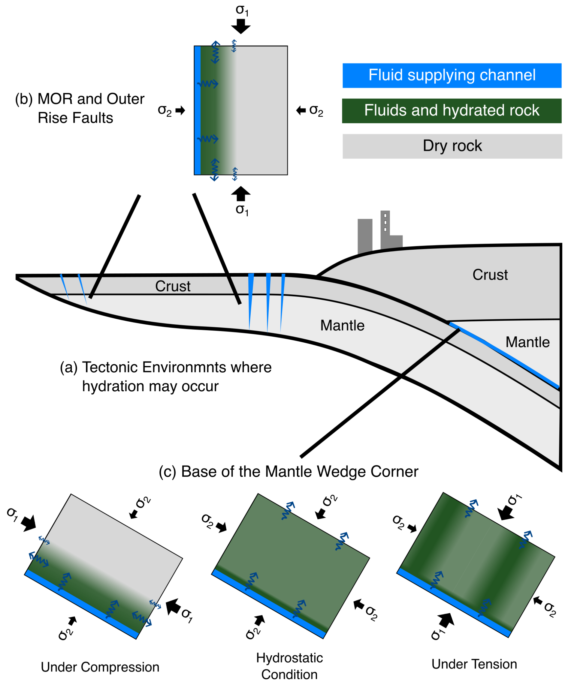
Figure 1Schematic diagram, illustrating (a) tectonic environments in which hydration can impact fracture evolution and fluid migration, and (b, c) possible fluid and hydration distributions that might be expected from the evolution of fracture due to volume-increasing hydration at (b) mid-ocean ridges and outer rises and (c) the base of the mantle wedge corner under compression, hydrostatic condition, and tension.
Here, we study the impact of reaction-induced stress and background differential stress on fracture evolution through 2-D hydraulic-chemical-mechanical modeling (Shimizu et al., 2011; Okamoto and Shimizu, 2015). Previous studies that employ similar numerical modeling approaches investigate reaction-induced fracturing at hydrostatic conditions (Yoshida et al., 2020; Shimizu and Okamoto, 2016; Zhang et al., 2019; Malthe-Sørenssen et al., 2006; Jamtveit et al., 2009). They report that the solid volume change associated with hydration leads to fracture that enhances the permeability of the reacting rock and its surroundings. However, the evolution of reaction-induced fracturing is likely impacted by the stresses associated with a given tectonic environment. Here, we take a step further by applying a range of differential stresses and investigate the relation between the differential stress and fracture evolution.
We use the 2-D numerical code DEFraG previously developed by Shimizu et al. (2011) and modified for simulating reaction-induced fracturing by Okamoto and Shimizu (2015). The code employs the distinct element method (DEM; Cundall and Strack, 1979; Potyondy and Cundall, 2004) and calculates the volume expansion in response to increasing fluid pressure, stress due to the volume expansion, and fracture due to the induced stress. A previous version of this code and similar codes have been used to investigate reaction-induced fracturing at hydrostatic conditions (Yoshida et al., 2020; Shimizu and Okamoto, 2016). These studies provide a foundation for the work presented here and support the veracity of the approach. The modeling approach is described in detail in Shimizu et al. (2011) and Okamoto and Shimizu (2015). Here, we provide a brief description.
2.1 Mechanical Modelling Approach
The modeled system is represented by a lattice of disks connected by elastic bonds, representing a small portion of rock relative to the length scale of the assumed fluid source (Fig. 2). The elastic properties of the bonds are described in terms of shear, tensile, and rotational stiffnesses (ks, kn, and kθ, respectively). The tensile and rotational stiffnesses are calculated based on Bernoulli-Euler beam theory, and the shear stiffness is calculated based on a chosen ratio between shear and tensile stiffnesses.
where is the cross-sectional area of the bond, defined as , where is the harmonic mean of the radii of the bonded disks and h is the thickness of the disk, which we take to be one, I is the moment of inertia, is the mean Young's modulus of the two disks, which scales the stiffness of the bond, ks0 is a constant, and L is the sum of the disk radii, representing the equilibrium length of the bond. The increment of contact force at a bond (ΔF) depends on the relative normal and shear displacements (Δn and Δs, respectively) of the disks at the bond:
Normal and shear stresses (σn and τs, respectively) on the contact are calculated based on the total force (F) on the bond.
where Fn and Fs are the normal and shear components of F. Compression results when disks overlap and tension results when bonded disks are displaced further from each other. At prescribed critical normal and/or shear stresses (σn,max and τs,max, respectively), the bond breaks and is replaced by a crack (hereafter we refer to breakage between two disks as a crack and longer breakage as a fracture). When a crack forms, the crack is classified as either shear or tensile in the model based on the maximum of the shear and tensile stress:
Contact forces at a crack only occur when disks overlap. Velocity and displacement of disks are calculated explicitly using the force on each disk. The velocity () and displacement increment (Δu) at time step t are given by (Cundall and Strack, 1979)
where Fd is the total force vector acting on a disk from all of its bonds, and Δt is the duration of the time step. Note that the force imparted on a disk by a bond may be either the positive or the negative of the contact force (Eq. 2), depending on the relative orientation of the disk to the bond.
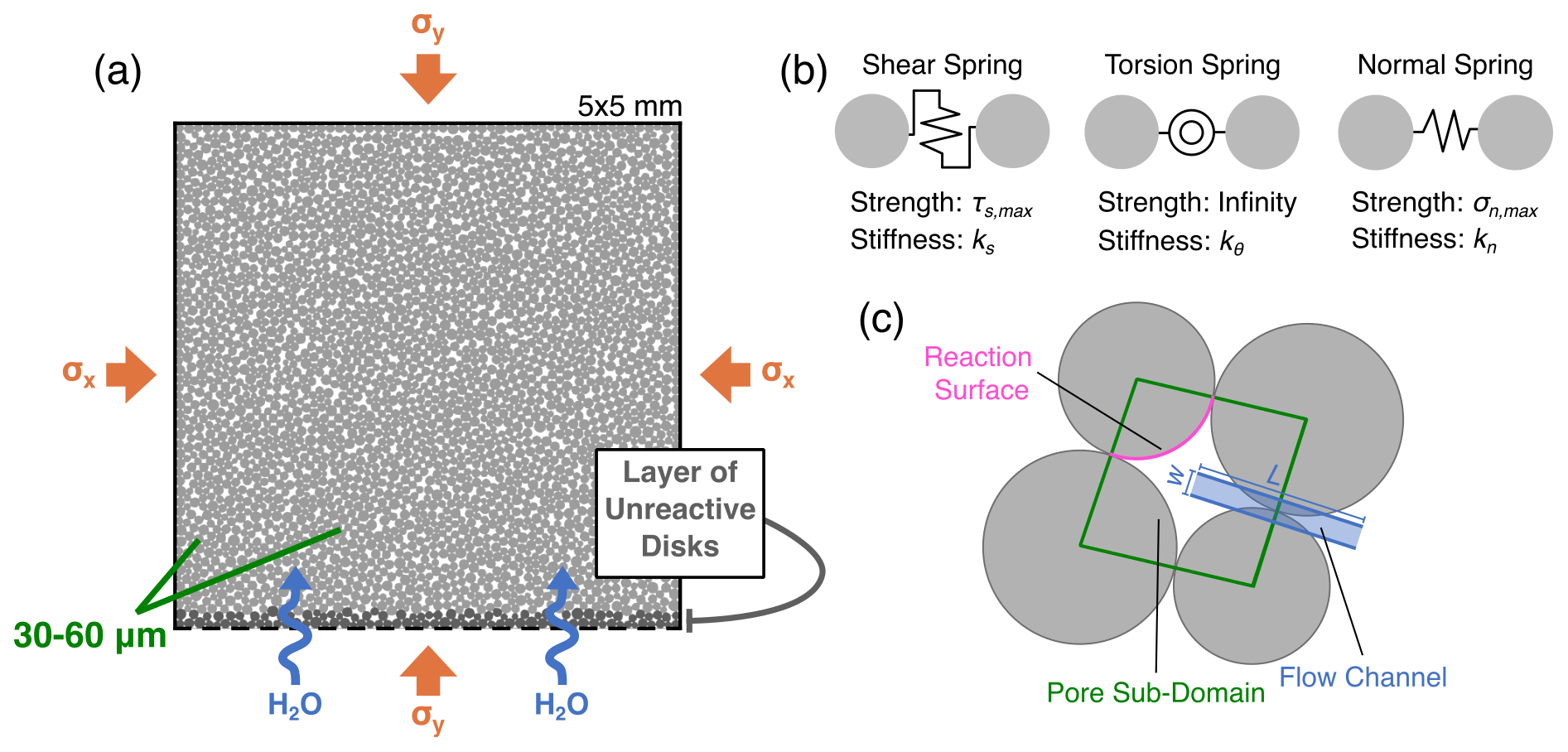
Figure 2(a) Model setup. Fluid pressure of 30 MPa is prescribed at the base of the model (black dashed line). The left, right, and top black solid lines indicate no-flow boundary conditions. Disk size is not necessarily representative of mineral grain size, but rather the length scale of heterogeneity in the rock strength. A highly permeable layer that consists of unreactive disks is placed at the base of the model to minimize boundary effects on the bottom-most reactive disks. (b) Shear, torsion, and normal springs representing components of elastic bonds. (c) Fluid flow model schematic. Green lines outline a pore sub-domain, and blue region represents an illustrative example of a flow channel between two adjacent pore sub-domains with L and w defined in Sect. 2.2, and pink surface represents example reaction surface for a single disk along a pore.
Because the model is formulated as a large number of bonds and disks, the macroscopic behavior is emergent such that parameters of the bonds must be calibrated to produce a desired macroscopic behavior. The calibration procedure is detailed in Shimizu and Okamoto (2016), and we use their calibrated microscopic mechanical properties: constant values of 30 MPa, 116 MPa, and infinity for the normal (σn,max), shear (τs,max), and rotational strengths, respectively, and 348 and 126 GPa for Young's moduli of the bonds between unreacted and fully reacted disks, respectively. In addition, we prescribe the ratios of shear to normal stiffness and rotational to normal stiffness to be 0.241 and 1, respectively, for unreacted disks, and 0.206 and 1, respectively, for fully reacted disks. Although we vary the elastic properties with the degree of hydration, previous modeling studies that employ similar approaches have reported that variations in both elastic properties and strengths of the rocks have relatively small effects on the overall pattern of reaction-induced fractures under hydrostatic conditions (Zhang et al., 2019; Okamoto and Shimizu, 2015).
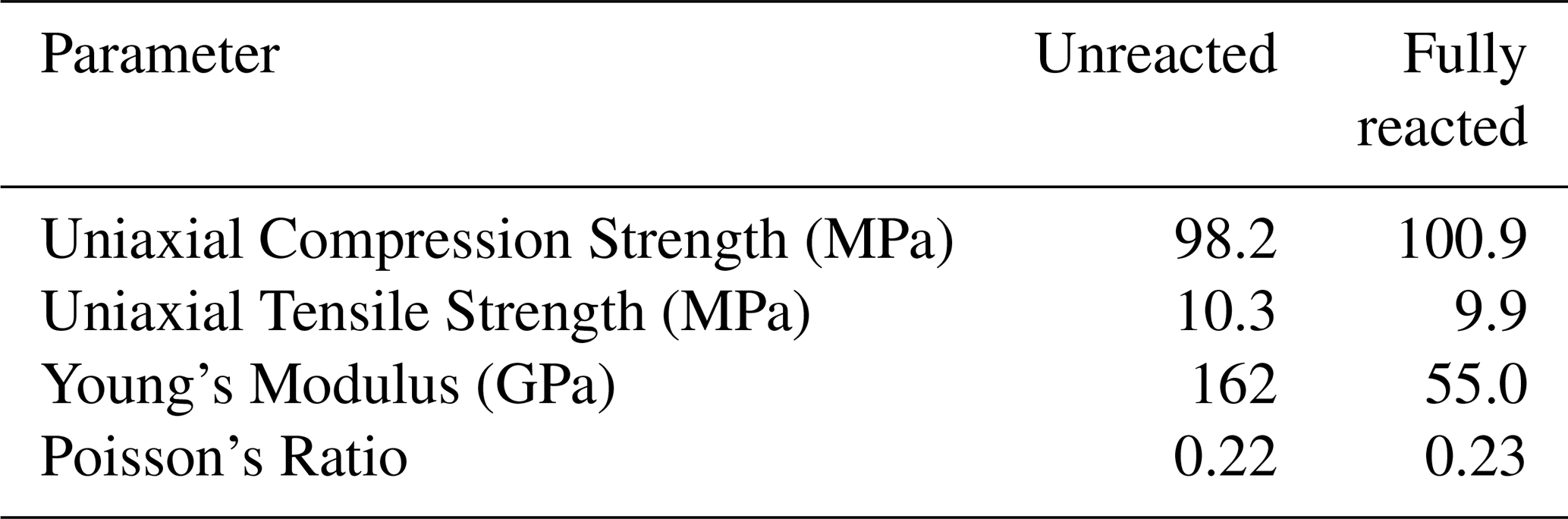
To verify that the chosen microscopic parameters produce reasonable macroscopic behavior, uniaxial compression and uniaxial tension strength tests were simulated using models composed completely of unreacted or fully reacted disks (Fig. S1 in the Supplement). These microscopic parameter values yield macroscopic elastic properties (i.e., Young's modulus and Poisson's ratio) of unreacted and reacted disks that are comparable to values reported in the literature for peridotite and an average of those for pure lizardite and pure brucite, respectively (Christensen, 2004) (Table 1). These analogs are useful given the prevalence of peridotite hydration to serpentinite in ultramafic tectonic environments. Additionally, both unreacted and reacted material exhibits approximately 10 MPa uniaxial tensile strength and 100 MPa uniaxial compressive strength, which are comparable to the strengths of common rock (Pollard and Fletcher, 2005). The choice of these values maintains consistency with previous studies (Shimizu and Okamoto, 2016) and is also useful for comparison.
Table 1Macroscopic mechanical properties of models composed entirely of unreacted and reacted disks.
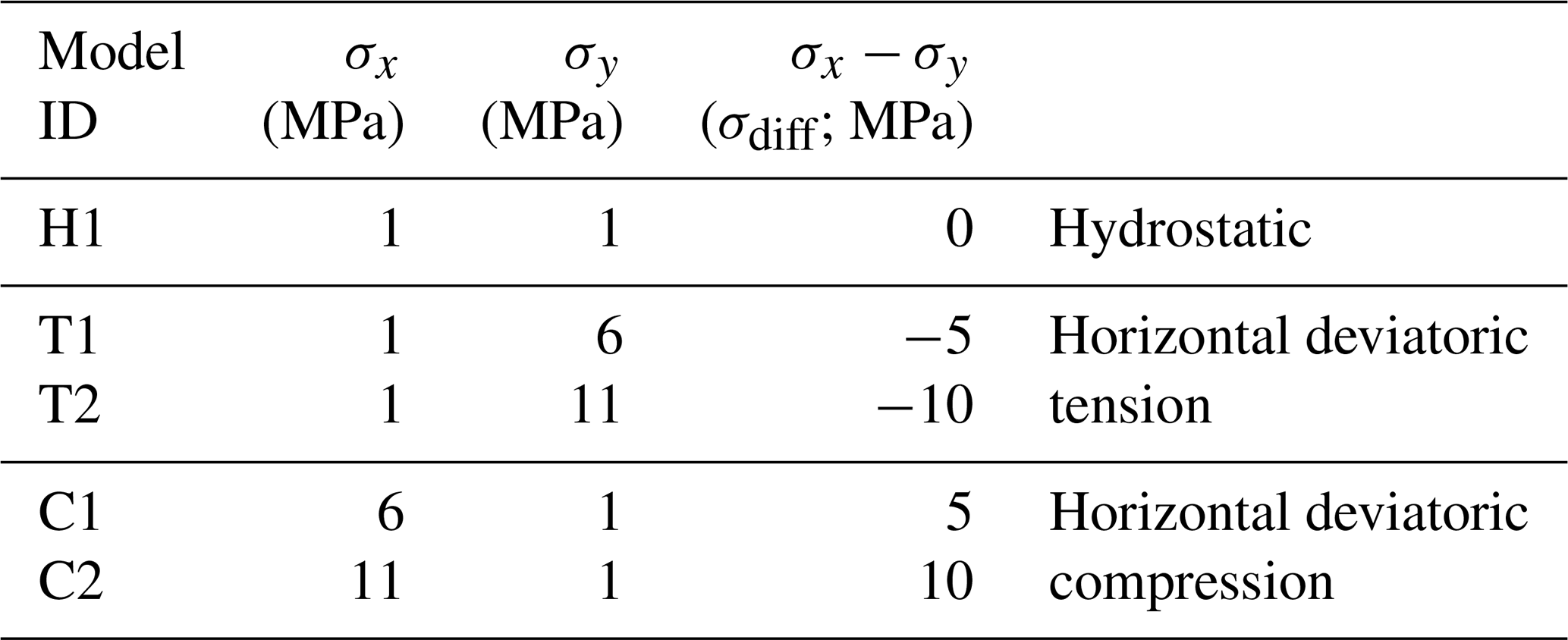
All models are 5 mm in width and height and consist of 3151 disks with 30–60 µm radii (average of 44.7 µm). The disks are packed randomly into the model domain, but the packing is identical in the simulations presented in this study. Previous work indicates that the variance of model behavior due to differences in the initial disk packing is small (Shimizu et al., 2010). An additional set of simulations with a different initial disk packing (Fig. S2 in the Supplement) displays similar behavior to those in Figs. 3–6, although there are minor variations. The confining pressure σc is 1 MPa for all models. For non-hydrostatic conditions, we vary the magnitudes of the horizontal and vertical stresses (σx and σy, respectively) (Fig. 2) and describe the stress condition as either horizontal deviatoric compression or tension (hereafter simply referred to as compression and tension, respectively) (Table 2). The left, right, top, and bottom boundaries are rigid but can move to maintain the applied stress.
2.2 Hydraulic Modeling Approach
Fluid flow is modeled using a pore network style approach (Fatt, 1956). Pore sub-domains between disks are occupied by fluids. Pore sub-domains are delineated by boundaries connecting the centers of neighboring disks. The volume of each pore, which we call the pore space, is equal to the space in each hydraulic sub-domain that is not occupied by the disks. Due to the circular shape of the disks, the porosity in the model is unrealistically large. Therefore, we scale the pore space in the simulation to be 1 % of the actual pore space.
Fluid flow driven by fluid pressure gradients occurs between pores via channels between bonded disks and cracks that form between disks. We refer to these two types of flow as matrix flow and fracture flow, respectively. Matrix flow represents flow governed by the initial permeability of the reacting material governed by, for example, connectivity of pores, diffusion, or thermal cracking (e.g., Yoshida et al., 2020; Roumejon and Cannat, 2014; Boudier et al., 2009). In both cases, imaginary pipes are placed between disks to represent flow channels, and the volumetric flow (Q) through the channel is calculated using the laminar flow equation
where ΔP is the pressure gradient, ν is the fluid viscosity, and w is the aperture of the channel. is the length of the channel (Fig. 2). For disks that are in contact at a bond or crack, the channel aperture depends on the force (Fn) acting on the channel
where w0 is the characteristic aperture of a channel subject to no forces, defined separately as wm at a bond and wf at a crack. F0 is the force necessary to close the channel halfway (i.e. ). Therefore, the aperture of a channel decreases under compression. This is one key difference between the methodology of this study and the methodology in Shimizu and Okamoto (2016), where only the channel aperture at cracks depended on the compressive stress on the channel, and the channel aperture at bonds was constant. Additionally, for two disks that have a crack and are not in contact, the aperture is taken as the sum of the disk separation distance and wf. The increment of pore pressure (ΔPd) in a sub-domain depends on the total inflow from neighboring sub-domains, ∑QΔt, the change in pore space volume in the sub-domain, ΔVd, and the volume of fluids consumed by the reaction, ΔVfluid, described in Sect. 2.3:
Kf is the bulk modulus of the fluid, and Vd is the volume of the pore space.
The initial fluid pressure in all models is set everywhere to the minimum value of fluid pressure (Pmin) that needs to be overcome before the reaction can proceed. The maximum fluid pressure (Pmax) at which the reaction proceeds at a prescribed maximum rate (Zmax) is maintained at the base of the model. The other three boundaries are impermeable, mimicking standard experimental setup (i.e. Uno et al., 2022), and they also prevent long computation times that arise from continuous, rapid flow within fractures between the fluid supply and draining boundaries. We use Pmin of 29 MPa and Pmax of 30 MPa. Pore fluids do not exert pressure on the model boundaries. Therefore, the simulation behavior is not sensitive to the magnitude of Pmax. The difference between Pmax and Pmin is less than the strength of the bonds such that hydrofracturing does not occur. This choice is made to evaluate the effects of reaction-induced and tectonic stresses on fracture in the absence of hydrofracturing. Fluids may exert significant stresses and contribute to fracture in tectonic settings where the pore pressure is high and sharp fluid pressure gradients are present. The scenario modeled in this study is one where pore pressure gradients are relatively low such that hydrofracture is negligible. Additionally, the difference between Pmax and Pmin is much smaller than the pore pressure decrease caused by 100 % reaction of an average radius disk. As a result, the reaction rate is controlled by the rate of fluid flow/supply to pore spaces. The relation between the reaction rate and the fluid pressure is further described in Sect. 2.3 below.
2.3 Chemical Modelling Approach
When disks are in contact with fluid and the fluid pressure is greater than Pmin, they react and consume the fluid. In our simulation, the complete reaction is accompanied by a 50 % solid volume increase and a 20 % total (solid + fluid) volume decrease. These values are comparable to those reported for serpentinization, which involves dissolution and replacement of the reacting material (Malvoisin et al., 2015, 2021, 2020; Malvoisin, 2015; Klein and Le Roux, 2020). In the model, this volume expansion occurs as a radially symmetric expansion of the reacting disks. The elastic parameters of partially reacted disks vary linearly between those of unreacted and completely reacted disks (Sect. 2.1) as the reaction of each disk progresses.
Disks consume fluids at a reaction rate Z. We use the following reaction rate equation (Shimizu and Okamoto, 2015):
where P is the local fluid pressure. A positive, linear, fluid-pressure dependence is reported for serpentinization (Wegner and Ernst, 1983). The increment of reacting volume of a disk (ΔVr=ZArΔt, where Ar is the area of reaction surface; Fig. 2c) results in an increment of fluid volume change (ΔVfluid=αΔVr). The solid volume increase is isotropic across each disk, and the radius of the disk (r) is a function of reaction degree ξdisk:
where r0 is the initial radius of the disk before any reaction. The constants α and β are −0.7 and 1.5, which were chosen to produce the specified effective 20 % total volume decrease and 50 % solid volume increase, respectively. In the model, if Zmax is too high, large stress gradients develop in a single timestep, resulting in artificial spontaneous fracture, and the resulting cracks have previously been referred to as “inertial cracks” (Shimizu and Okamoto, 2016). Previous studies report stable reaction rates that minimize the occurrence of inertial cracks at hydrostatic stress conditions (e.g., Shimizu and Okamoto, 2016; Okamoto et al., 2017) but not under differential stresses. Through a series of simulations with different Zmax values, we find that the crack density loses its reaction-rate dependence when Zmax is lower than 25 s−1, and inertial cracks are largely absent although the orientation of cracks and the ratio of shear to tensile cracks vary with the reaction rate, impacting the resulting fracture texture (Fig. S3 in the Supplement). Further analyses indicate that the ratio of shear to tensile cracks converges near Zmax=5 s−1. To avoid the formation of artificial cracks and minimize the impact of Zmax on fracture texture, we use Zmax=5 s−1 for all models except the hydrostatic case, for which we use Zmax=1 s−1 to reduce the fluid flow rate to avoid anomalously long computation times (Sect. S1 in the Supplement).
In the model calculation, very small time steps ( s) are required to maintain numerical stability. To keep computation times reasonable, reaction rates much faster than expected to be in nature are used. The maximum reaction rate Zmax is roughly eight orders of magnitude larger than the rate reported in lab experiments on olivine powders at 300 °C (Malvoisin et al., 2012; Shimizu and Okamoto, 2016). Therefore, fluid flow rates are scaled by the reaction rate:
where Qm is the characteristic volumetric matrix flow rate between two bonded disks, Qf is the characteristic volumetric fracture flow rate in a crack, and Qr is the characteristic volumetric rate of fluid consumption, as described in Shimizu and Okamoto (2016). Qm and Qf are calculated based on chosen values for w0 for channels between bonded disks and cracks, respectively. Laboratory experiments on the hydration of periclase to brucite, commonly used as a proxy for general volume increasing reactions, and computer modeling work on reaction-induced fracturing indicate that the behavior of these systems depends on ψ rather than the absolute reaction rate and permeability (Uno et al., 2022; Shimizu and Okamoto, 2016, Ulven et al., 2014b). In particular, reaction-induced fracturing only occurs when ψm is below a critical value of 100, and textures similar to those seen in nature develop only when ψf is above a critical value of 1000 (Uno et al., 2022; Shimizu and Okamoto, 2016). In this study, we run models with either moderate or high value of ψm (1 or 10) for reactive disks and use ψf of 10 000 for all models.
In all cases, fluid is supplied at the base of the model. We include a layer of unreactive material at the base of the model domain to minimize the effects of nonrandom bond orientations due to alignment of disks against the boundary (Fig. 2). Exclusion of this layer results in artificially high apparent strengths of the bonds between the first disks to react. We use ψm of 10 000 for the unreactive layer. Fluids supplied to the base of the model domain percolate upwards through this layer and begin reacting with the reactive material above it. The scenario is akin to fluid migration away from a fluid-supplying channel, such as a pre-existing fracture, a fault, or a subduction interface, represented by the base of the model, into the neighboring rock.
Models were run to a bulk reaction completion, Δ, of 1.5 %–3.0 % depending on the computation time. Previous work has shown that existing fractures accommodate subsequent deformation past a few reaction percent (Yoshida et al., 2020; Shimizu and Okamoto, 2016), and field observations indicate the majority of reaction-induced cracking occurs during early stages of serpentinization (e.g., Kelemen and Hirth, 2012). Furthermore, at the conditions of the models, the volume expansion is so large that stresses sufficient to fracture the model can be achieved at only small reaction percentages. Therefore, the simulated degree of reaction completion is likely sufficient to capture the primary fracture behavior.
We limit our analysis to three stress conditions: hydrostatic, deviatoric tension, and deviatoric compression. We define the latter two conditions based on the orientation of the maximum compressive principal stress (σ1) relative to the initial fluid-supplying channel (Fig. 2): σ1 normal (σ1=σy) and parallel (σ1=σx) to the channel, respectively. The effective confining pressure in all simulations is 1 MPa unless stated otherwise. This relatively low confining pressure is used to ensure numerical stability in the calculation of stress due to volume expansion as in previous studies. Given the sensitivity of reaction-induced fracturing to numerous parameters, as established in previous studies (Ulven et al., 2014b; Shimizu and Okamoto, 2016), the results of this study are used to investigate the trend in the fracture behavior with differential stress, and the aim is not to investigate reaction-induced fracturing in a specific tectonic environment. However, we later assess the implication of the modeling results to the interpretation of geophysical and geologic observations of hydration in the oceanic lithosphere at mid-ocean ridges and outer rises and the forearc mantle wedge corner in subduction zones.
We run simulations under deviatoric tension, a hydrostatic condition, and deviatoric compression (Table 2; Figs. 3–6). We first describe the model under a hydrostatic condition and use it as a reference model.
3.1 Reference Model under the Hydrostatic Condition
In simulations under the hydrostatic condition (1 MPa) (Model H1; Table 2; Fig. 3c), expansion of the bottommost reactive disks generates lateral compression amongst those reactive disks and lateral tension in the interior of the model, consistent with stress distributions observed in previous studies (Ulven et al., 2014b). The lateral tension in the interior causes localized sub-vertical mode I fractures to form. These tensile fractures are initially isolated from available fluids because the fluids cannot propagate across the layer of reacting disks that are under lateral compression. However, heterogeneities in the layer of reacting disks and shear cracks that form with continued reaction facilitate further formation of tensile fractures across the layer of reacting disks and allow eventual connection between the interior tensile fractures and the fluid supply at the base of the model. These tensile fractures subsequently channel large volumes of fluid into the model. Fluids are consumed by disks along these newly fluid-filled channels, generating new tensile stresses parallel to the channels and causing a second generation of tensile fractures to form subnormal to the first generation of fractures. We categorize the fracture pattern that develops under the hydrostatic condition as a branching fracture style. It is a result of hierarchical fracturing associated with a positive feedback loop, in which reaction-induced stresses generate tensile fractures that act as new fluid-supplying channels penetrating into the surrounding unreacted material, increasing its permeability and allowing further fluid infiltration and reaction. This branching process partitions the model domain into smaller sub-domains that are bounded by newly generated fractures. This branching fracture is distinct from the branching fracture patterns that are described to occur during solid volume reducing reactions (Okamoto and Shimizu, 2015). Because new tensile fractures propagate away from existing fluid filled channels, this fracture pattern consists of a relatively uniform mixture of low and high angle cracks (Figs. 3c.ii and 4c), and efficiently channels fluids into unreacted regions of the model, promoting spatially extensive hydration (Fig. 5c.i and ii).
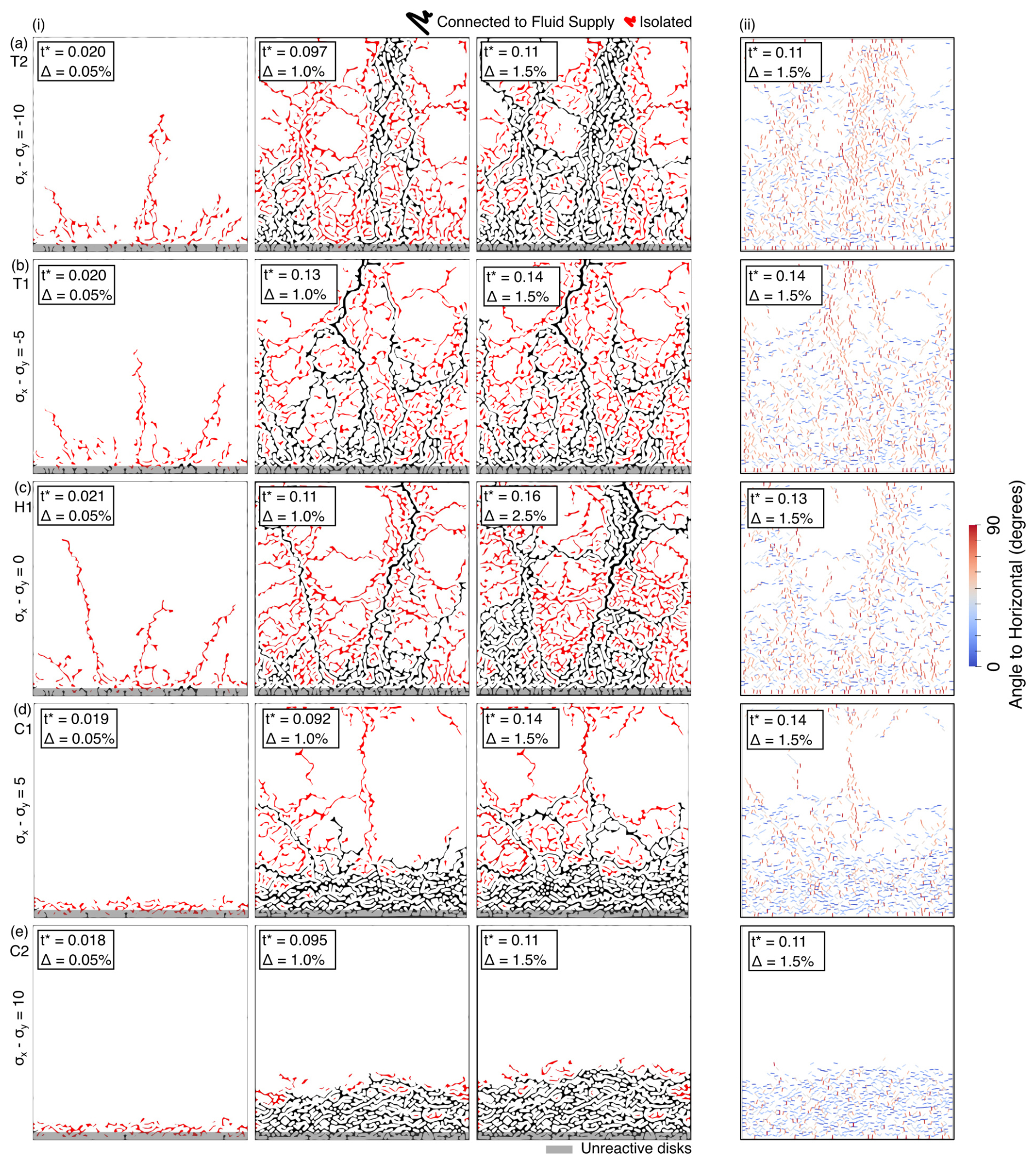
Figure 3(i) Fracture evolution (left three columns) and (ii) crack angle, ranging from 0° (horizontal; blue) to 90° (vertical; red) under (a, b) lateral deviatoric tension with differential stress (i.e., σx−σy) of −10 and −5 MPa, respectively, (c) hydrostatic condition, and (d, e) lateral deviatoric compression with differential stress of 5 and 10 MPa, respectively. t∗ is the nondimensionalized time. Black and red paths indicate fractures that are connected to and isolated from the fluid supply at the base of the model, respectively. The gray layer at the bottom of the model domain represents a region with unreactive disks. Hydrostatic condition is shown up to Δ=2.5 % to better illustrate progressive hierarchical fracturing.
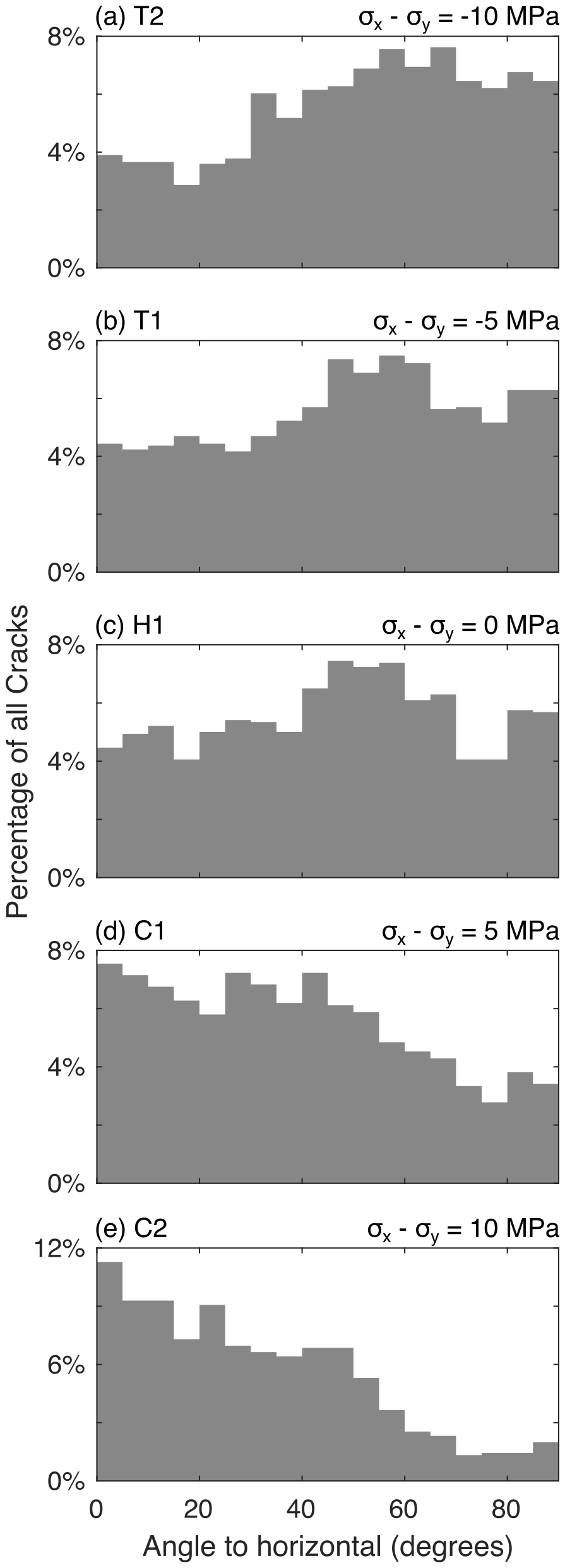
Figure 4Distribution of crack angles at Δ=1.5 % under (a, b) lateral deviatoric tension with differential stress (i.e., σx−σy) of −10 MPa, −5 MPa, (c) hydrostatic condition, and (d, e) lateral deviatoric compression with differential stress of 5 and 10 MPa, respectively.
We use the pore fluid pressure distribution to assess fluid migration into the system through fractures (Fig. 5c.i). High fluid pressures are localized along branching fractures that are connected to the fluid-supplying channel but decrease with distance from the fluid supply at the base of the model. The evolution of fluid pressure does not strictly follow that of fracture as many fractures are neither directly nor indirectly connected to the fluid supply at the base of the model. High fluid pressures are constrained to the cracks that are connected to the fluid supply because the matrix permeability is low and there is little fluid migrating away from the cracks. The hydration distribution generally follows the fluid distribution with some delay due to the time-dependence of hydration, and the highest reaction completion is along the base of the model (Fig. 5c.ii). Both the fluid and hydration distributions are impacted by crack aperture, which controls the fracture permeability. Fractures that are oriented normal to the initial layer of reacting disks have the largest aperture and therefore host the highest fluid flow rates, playing a critical role in hydrating the interior (Fig. 5c.iii). As new layers of reacting disks develop at the boundaries of the first generation of high aperture cracks, the resulting tensile stresses will then increase the aperture of a second generation of high aperture cracks normal to the first, allowing efficient flow into sub-domains. This results in a pore pressure distribution distributed throughout the interior of the model but localized along the fractures and a reaction distribution that is relatively low but distributed throughout the model along fluid channels, where it is localized.
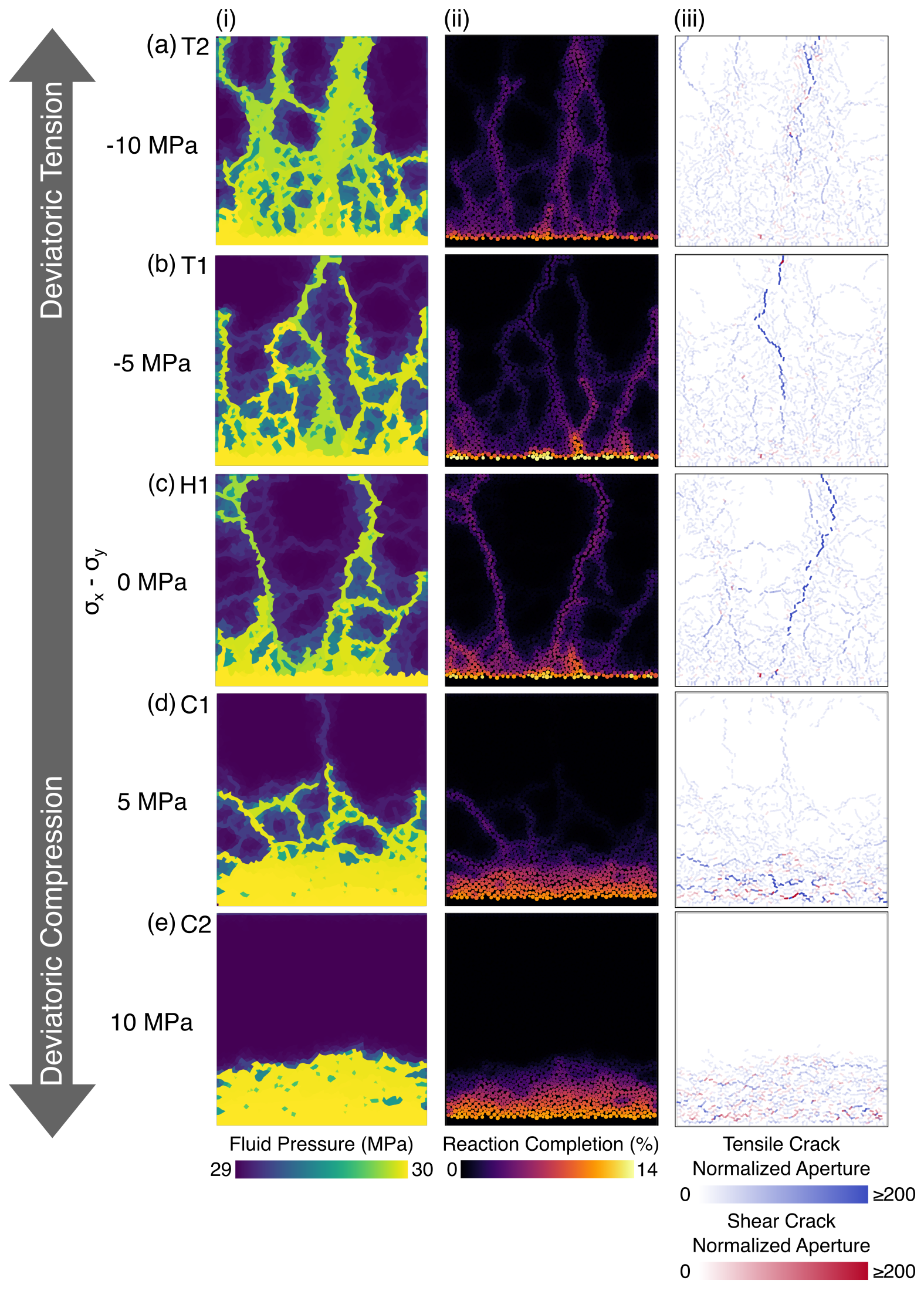
Figure 5(i) Fluid distribution, as measured by pore fluid pressure, (ii) reaction completion, indicating the level of volume expansion, and (iii) crack aperture at Δ=1.5 % under (a–e) lateral deviatoric tension with differential stress (i.e., σx−σy) of −10 MPa, −5 MPa, hydrostatic condition, and lateral deviatoric compression with differential stress of 5 and 10 MPa, respectively. The aperture of tensile and shear cracks (orange and purple lines, respectively) are normalized by the aperture of bonded, unstressed disks (w0) that characterize the matrix permeability.
New fractures are not immediately connected to the fluid supply to form the next generation of fluid channels, and therefore the overall fracture evolution exhibits a cyclic behavior, interceded by periods of stress buildup. Such cyclic behavior has been observed and described in previous numerical modeling studies (Okamoto and Shimizu, 2015; Shimizu and Okamoto, 2016) and experiments (Okamoto et al., 2025). These successive branching episodes result in a stepwise increase in fracture density (that is, the percentage of connecting bonds that are broken in the model) and flow rate into the model (Fig. 6a and b), and they correspond to sudden increases in the bulk reaction rate () (Fig. 6c). Because the length of vertical tensile fractures is limited by the top boundary of the model, fluid inflow is likely underestimated once the fractures reach the top boundary (Sect. S4 in the Supplement). Therefore, we refrain from directly comparing them with the inflow and reaction rates from other models.
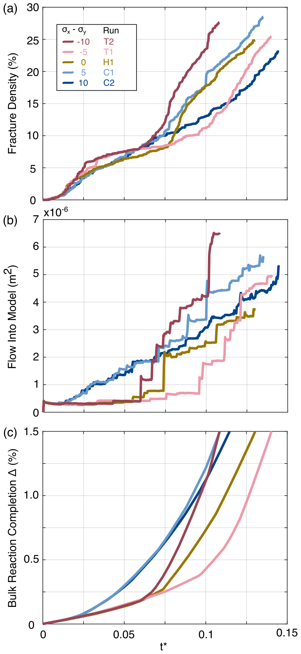
Figure 6Changes in (a) crack density, (b) fluid inflow rate, and (c) the bulk reaction completion (Δ) for the entire model domain with nondimensional time. In the tension and hydrostatic cases, crack density increases following each fluid in-flow pulse, before beginning to level off. The relative magnitudes of the values in (a)–(c) depend on the model dimensions (Sect. S4; Fig. S4 in the Supplement). Therefore, they cannot be directly compared with those measured in laboratory experiments.
3.2 Models under Horizontal Deviatoric Tension
The fracture evolution under vertical deviatoric tension is initially similar to those under the hydrostatic condition (Models T1 and T2; Table 2; Fig. 3a.i and b.i). Vertical tensile cracks propagate from the base of the model into the unreacted interior. Subsequent evolution indicates that when those fractures channel fluids, new cracks form normal to them, as in the hydrostatic case, but also parallel to them (Fig. 3a.ii and b.ii), resulting in more cracks with high angles relative to the distribution under the hydrostatic condition (Fig. 4a and b). This style of fracturing appears to be a hybrid of both the branching fracture described in the hydrostatic case, and a fracture style similar to “spalling” reported in previous studies (Ulven et al., 2014b; Jamtveit et al., 2009; Røyne et al., 2008). The spalling cracks are characterized by short, distributed fractures between and very near to reacting disks and, in our simulations, develop adjacent to fluid-filled channels that are parallel to σ1. Spalling cracks generally appear as layers of parallel cracks along fluid channels (Fig. 3a.ii and b.ii). Note that in the hydrostatic model, while cracks around vertical channels are largely of the branching type, some spalling cracks may develop along fluid channels due to the local deviatoric compression that develops due to the expansion of disks along the channel, but they are much less prevalent than in the models under tension.
Similar to the hydrostatic case, the distributions of fluid and hydration follow the distribution of fractures that are connected to the fluid supply (Fig. 5a.i, ii and b.i, ii). However, due to spalling around fluid channeling fractures, high pore pressure occurs in a wider zone along the channels. As a result, the width of reaction distribution along channels is large and increases as spalling occurs. Cracks oriented vertically have the highest apertures (Fig. 5a and b.iii). However, apertures in models under deviatoric tension are generally smaller than under hydrostatic conditions, likely because the larger number of fractures around the main channels leads to reaction-induced stresses that discourage the widening of neighboring channels (i.e., larger Fn in Eq. 2 in Methods). Both the fracture density and the inflow rate exhibit the same cyclic behavior as in the hydrostatic case, but due to the large number of vertical fractures, the average increase in inflow rate is significantly higher than in the hydrostatic case (Fig. 6).
3.3 Models under Horizontal Deviatoric Compression
Fracture evolution under horizontal deviatoric compression ( and 10 MPa) initially exhibits behavior that is significantly different from that of the hydrostatic and deviatoric tension conditions (Models C1 and C2; Table 2; Fig. 3d.i and e.i). Fracture evolution in these simulations occurs in two stages: an early stage dominated by spalling fracture, and a later stage dominated by branching fracture. The timing of the transition from the early to the later stage depends on the magnitude of deviatoric compression.
In the early stages of hydration, expansion of the bottommost disks generates compression in the reacting region, similar to those under the hydrostatic condition and horizontal deviatoric tension. However, cracks develop between and near the reacting disks before significant tensile stresses are able to build up in the unreacted interior. These cracks are both tensile and shear although tensile cracks are more common, and their pattern resembles the spalling fracture reported in the deviatoric tension simulations. They are predominantly at low angles and subparallel to the fluid supply at the base of the model, although there are a small number of high angle cracks (Fig. 3d.ii and e.ii), resulting in more cracks with low angles relative to the distribution under the hydrostatic condition (Fig. 4d and e). The interior of the model remains under horizontal deviatoric compression due to background stress, preventing the propagation of fractures into the unreacted interior.
Unlike in the hydrostatic and horizontal deviatoric tension cases, long sub-vertical tensile fractures do not form under horizontal deviatoric compression. Without those fractures, fluids are not channeled far into the unreacted rock, and spatially pervasive reaction does not occur throughout the model (Fig. 5d.i, ii and e.i, ii). Instead, the spalling fracture pattern results in high fluid pressures and reaction degrees in a wider zone along the fluid supply at the base of the model. This zone grows in width as spalling gradually propagates into the interior of the model. In these simulations, fractures with the largest aperture tend to be oriented subparallel to the fluid supply at the base of the model (i.e., in the direction of maximum principal stress) (Fig. 5d.iii and e.iii). All cracks near the base of the model quickly become well connected to each other and to the fluid supply. As a result, fluid flow into the model correlates more closely to the crack density than in the hydrostatic or deviatoric tension simulations (Fig. 6).
When the magnitude of horizontal deviatoric compression is small (i.e., MPa), once the spalling region expands sufficiently far into the model, a second stage occurs wherein tensile cracks develop at high angles to the layer of spalling fractures. This occurs because the remaining unreacted part of the rock can no longer support the tension due to the expansion of the reacted disks. For this reason, in simulations in which the model domain is taller, the second stage occurs later (Sect. S4). The tensile cracks that form as part of the second stage propagate into the unreacted interior, and a branching fracture pattern develops in their vicinity. However, they occur at a shorter length scale and curve sharply to align themselves with the applied horizontal compression. This second stage of fracturing occurs earlier in the simulation with a lower degree of compression (i.e. MPa) than in the more compressive case ( MPa), indicating that the timing of this second stage depends on the magnitude of horizontal deviatoric compression.
4.1 Primary Fracture Style and Its Transition with Differential Stress
Under the hydrostatic condition (Model H1; Fig. 3c), the reaction-induced local deviatoric tension that initially develops in the interior due to the hydration of the bottom most disks is parallel to the fluid-supplying channel, resulting in the branching primary fracture style, as discussed in Sect. 3.1. Under background differential stress, the primary fracture style depends on the orientation of the fluid-supplying channel relative to σ1. Under tension (Models T1 and T2), the initial fluid-supplying channel, corresponding to the bottom boundary of the model, is normal to σ1, resulting in branching style fracture. Conversely, under compression (Models C1 and C2), the initial fluid-supplying channel is parallel to σ1, resulting in spalling style fracture as the dominant style. As discussed in Sect. 3.1 and 3.2, some spalling does occur along subvertical fluid-supplying channels under tension, because these channels are parallel to σ1 in addition to the reaction-induced local deviatoric stress imposed by reacting regions, similar to the model under the hydrostatic condition. However, these spalling fractures are secondary.
Applied compression promotes spalling parallel to fluid channels by working with compressive reaction-induced stresses and working against tensile reaction-induced stresses. In our simulations, the transition in the primary fracture style occurs under compression near 5 MPa (Model C1). Near this transition, spalling is still the primary fracture style, but it gives way to branching after sufficient reaction completion. While a transition from branching to spalling with increasing background compression parallel to fluid-filled channels is a general trend, the background stress value at the transition is specific to our model setup because it is sensitive to the reaction-induced stress distribution, which depends on factors that may vary between individual settings, such as the initial permeability, reaction-induced volume change, and domain size (Ulven et al., 2014a, b; Røyne et al., 2008; Sect. S5 in the Supplement).
The occurrence of branching after some amount of spalling near the transition (Model C1) is consistent with field observations of weathered rocks (Røyne et al., 2008; Iyer et al., 2008), with numerical models (Røyne et al., 2008; Jamtveit et al., 2009), and with observations from laboratory experiments (Okamoto et al., 2025). Previous authors have argued the transition to branching to primarily be a result of changes in the unreacted domain size as spalling progresses (Røyne et al., 2008). This argument is consistent with our modeling results, which exhibit branching when spalling fractures have extended far enough into the model as discussed above. Those spalling fractures efficiently channel fluids into the rock in our models, and therefore the pore pressure and resultant reaction-induced stress distribution change as spalling progresses. The primary reaction-induced fracturing style under channel-parallel compression is then time-dependent, and spalling may represent only a first stage of reaction-induced fracturing. The orientations of branching fractures that occur under compression after spalling still follow the primary orientations of the spalling fractures and tend to be parallel to the maximum applied background stress because they curve to orient themselves with the background σ1. At higher compression, this fracture pattern evolution can happen after a longer period of simulation/hydration.
The transitional background stress of 5 MPa from our simulations reflects the magnitude of the local deviatoric stress that offsets the background stress. Based on upper bound thermodynamic estimates of the crystallization stress due to serpentinization, tensile crack propagation characteristic of the branching fracture pattern should be possible for background stresses of up to 100s of MPa (Malvoisin et al., 2017). The apparent discrepancy in the background stresses for branching fracture between the thermodynamic calculations and our models may occur because spalling cracks accommodate strain and hinder subsequent stress build-up. Kelemen and Hirth (2012) noted a similar contrast between theoretical and observed reaction-induced stresses in natural serpentinites and attributed the differences to strain accommodation by existing fractures. Although the exact value of differential stress for the fracture style transition in our simulations is specific to the model parameters and the initial and boundary conditions used, the results indicate that the style of reaction-induced fracturing may be sensitive to a relatively small change in the background stresses (e.g., a change from 0 to 10 MPa).
4.2 Fluid and Hydration Distributions
In both fracture styles, differential stress impacts the primary orientation of high-aperture cracks. Therefore, the contrasting fracture styles produced under differing background stress conditions might have significant impacts on fluid flow during hydration. Branching fracture results in a distributed fracture network that promotes a spatially extensive fluid and hydration distribution at the model scale. During branching, fractures that form sub-normal to fluid-supplying channels tend to have the highest apertures and propagate far into unreacted regions, channeling fluids into the interior of unreacted rock. In contrast, during spalling fractures parallel to fluid filled channels have the highest apertures, and the fluid and hydration distributions are localized along fluid channels. A similar spalling fracture pattern along the fluid supply is observed in experiments at high mean normal stress (Okamoto et al., 2025). Given the relative orientation of the fluid channel and spalling fractures, the region with relatively high fluid content and degree of hydration tends to form parallel to σ1. Additionally, the highest aperture cracks are parallel to σ1, potentially guiding mesoscale fluid flow direction under tectonic stress.
4.3 Implications of Fracture Styles for Geological Processes and Comparison to Observations
At mid-ocean ridges and outer rises, hydration of the oceanic crust and mantle occurs and plays an important role in sequestering water into the oceanic lithosphere. Sequestered fluids are released during subduction of the oceanic lithosphere, and some of the released fluids are taken up by hydration of the surrounding material, such as the overriding mantle wedge. Based on our modeling results, whether the hydration is localized or distributed in these environments could potentially depend on the orientations of fluid-supplying channels relative to σ1 (Fig. 1b and c).
At mid-ocean ridges and outer rises, the oceanic plate experiences approximately surface parallel deviatoric tension due to gravitational forces that pull the oceanic plate downslope, and bending, respectively (Fig. 1b). In both settings, the tectonic stress state results in normal faulting that provides an initial fluid channel into the lithosphere (Faccenda et al., 2009; Seno and Yamanaka, 1996). However, fluid migration away from these faults into the wall rock likely depends on the microscopic permeability of the wall rock (Hatakeyama et al., 2017), which may be impacted by reaction-induced fracturing. The faults are subvertical and subparallel to σ1, similar to the initial boundary conditions of models under compression (Models C1 and C2). These models predict spalling and localized hydration along the normal faults. Seismic and electromagnetic surveys indicate the presence of deep cutting normal faults and hydration along them (e.g., Ranero et al., 2003; Naif et al., 2015; Obana et al., 2019). Although the length scale of our simulations is much shorter, the model-predicted spalling fracture style may contribute to the inferred localization of hydration along deep-cutting faults.
Hierarchical fracture networks are frequently reported in serpentinites from mid-ocean ridges (Shimizu and Okamoto, 2016; Malvoisin et al., 2017; Roumejon and Cannat, 2014; Boudier et al., 2009; Jamtveit et al., 2009; Raleigh and Paterson, 1965). The hierarchical fracture network shares a similar fracture pattern to branching fracture in our hydrostatic simulations, but contrasts with the spalling that dominates under compression. Therefore, model-predicted spalling around the normal faults is inconsistent with textures of mid ocean ridge serpentinites. Since the transition from branching to spalling is predicted to occur under some compression parallel to the fluid channel, this may imply that the vertical stress relative to the horizontal stress may be too low to promote spalling. However, simulations under low differential stress (C1) indicate that the fracture pattern changes from spalling to branching after the spalling front has migrated a sufficient distance into the model. Therefore, the observed hierarchical fracture may record the fracture pattern from the later stage of hydration. Another interpretation is that the samples exhibiting hierarchical fracture may represent reaction-induced fracturing along fluid-supplying channels that form sub-normal to the normal faults. Alternatively, high initial permeability may promote branching, per previous studies (Ulven et al., 2014b). Recent studies have reported that normal faults that form in the mid-ocean ridge environment may be reactivated as thrust faults as the oceanic plate moves away from the ridge (Olive et al., 2024), indicating that σ1 can become subnormal to faults. Therefore, one additional possibility is that mesh-texture serpentinites formed under this condition, although it is not clear how much fluid can migrate down such faults that are being compressed.
At subduction zones, geophysically-inferred stress orientations and lithospheric deformation models indicate that the state of stress in the overriding lithosphere in the forearc region can be horizontal margin-normal deviatoric compression to tension (Fig. 1c) and has been attributed to the variation of the plate coupling force relative to the gravitational force (Wang and He, 1999; Sharma et al., 2025). The overriding forearc mantle wedge corner in subduction zones is decoupled from the subducting slab and cold (e.g., Furukawa, 1993; Wada and Wang, 2009), acting as part of the overriding lithosphere. The distribution of hydration by slab-derived fluids may be impacted by reaction-induced fracturing under background tectonic stress. Assuming that the subduction interface represents a fluid-supplying channel and that the interface is shallowly dipping, the horizontal margin-normal deviatoric compression and tension correspond to channel-parallel compression and tension for the initial stage of hydration, respectively. Our models indicate that these stress conditions promote spalling and branching, respectively.
In forearcs under margin-normal horizontal deviatoric tension and a near hydrostatic condition, hydration might be accompanied by branching fracture or a hybrid of branching and spalling similar to those predicted by Models H1, T1, and T2. Fractures in this case efficiently channel fluids into the interior of the mantle wedge corner and facilitate extensive hydration. In forearcs under margin-normal deviatoric tension or where the margin-normal and vertical stresses are similar, such as SW Japan (Saito et al., 2018) and Cascadia (Wang and He, 1999; Balfour et al., 2011; Sharma et al., 2025), a relatively high degree of mantle wedge corner serpentinization is reported (Bostock et al., 2002; Saita et al., 2015; Kato et al., 2010; Kamiya and Kobayashi, 2000). The branching fracture pattern is similar to hierarchical fracture patterns exhibited in exhumed serpentinites and carbonates from, for example, the New Caledonia and western Mongolia paleo-subduction zones (Dandar et al., 2019; Raia et al., 2022), potentially providing clues to the background tectonic stresses.
In forearcs under margin-normal horizontal deviatoric compression, more localized hydration at the base of the mantle wedge corner is expected due to the model-predicted spalling style fracture. Such spalling fracture might guide fluids updip along the interface and prevent extensive fluid flow into the mantle wedge corner. In fact, there are little observations that indicate spatially extensive serpentinization in the mantle wedge corner under margin-normal compression, such as in NE Japan (Miura et al., 2005) and Chile (Carlson and Miller, 2003). Furthermore, localized hydration at the base of the mantle wedge has been invoked to explain high Poisson's ratios observed atop the subduction interface in much of NE Japan (Kawakatsu and Watada, 2007). Experimental results report localized fluid flow within sheared serpentinites due to the resulting permeability anisotropy (Kawano et al., 2011; Okazaki et al., 2013). This mechanism may be operating in parallel with the mechanism we propose here for updip fluid migration. Exhumed mantle wedge serpentinites from the Sanbagawa belt exhibit foliations containing antigorite with textures that are somewhat comparable to the spalling in our horizontal compression models (Mizukami et al., 2014; Okamoto et al., 2024).
The results here are applied to the stagnant mantle wedge corner, which is at relatively low temperatures and likely undergoes brittle deformation. Modeling studies by Wilson et al. (2014), Cerpa et al. (2017, 2019), and Cerpa and Wada (2025) on fluid flow in a viscously deforming solid, indicate compaction pressure gradients generated by deformation of the solid matrix may impact fluid migration (McKenzie, 1984; Spiegelman, 1993). While they apply the model to regions in subduction zones that are generally at higher temperatures and pressures (higher Maxwell number) where brittle deformation is discouraged, as discussed in Cerpa and Wada (2025), brittle deformation, such as reaction-induced fracturing, may occur within their model domain of the subducting slab where the temperature is relatively low. Within the slab, both dehydration and hydration reactions can occur, potentially inducing reaction-induced fracturing. As shown in our study, the pattern of such fractures depends on the state of stress, impacting fluid migration. The slab tends to experience downdip tension at intermediate depths due likely to the slab pull, a key driving force of subduction (e.g., Isacks and Molnar, 1971; Vassiliou and Hager, 1988), but the details of stress distribution are impacted by various factors, such as the elastic bending of the slab at the trench and subsequent unbending downdip (e.g., Hasegawa et al., 1978), lateral bending due to margin curvature (Wada et al., 2010), interaction of the slab with the transition zone and the lower mantle (Goes et al., 2017), and the age and the strength of the slab (Chen et al., 2004). Therefore, the style of reaction-induced fracture is likely to spatially vary with the stress orientations within the slab, and the combined effects of the permeability structure due to reaction-induced fractures and compaction pressure gradients due to viscous deformation may generate a complex pattern of fluid migration.
4.4 Limitations of This Study
In this study, simulations were run at low effective confining pressure of 1 MPa, which may be lower than the effective confining pressure in the tectonic environments discussed above. Hydration may occur at overburden pressures of up to several 100 MPa along normal faults in mid-ocean ridges and outer rises and around 1–2 GPa at the base of the mantle wedge corner. Although the effective confining pressure is likely to be lower due to pore fluid pressure, which may vary from low to supralithostatic in subduction zones (e.g. Audet and Schaeffer, 2018), further investigation on the role of confining pressure is required to extend quantitative analyses of reaction-induced fracturing to these environments.
Additionally, serpentinization and therefore reaction-induced fracturing may occur at temperatures up to ∼ 600 °C. At these temperatures, the serpentinization rate is much lower than its maximum rate at roughly 300 °C (Malvoisin et al., 2012), and therefore the strain rate due to the volume increasing reaction is probably low. The yield stress of serpentine depends positively on the temperature and negatively on the strain rate (Burdette and Hirth, 2022; Horn and Skemer, 2025), and so at these temperatures, non-dilatant plastic deformation may occur (Malvoisin et al., 2021; Skarbek et al., 2018) if the yield stress is lower than the brittle strength. This style of deformation, which would likely accommodate strain but does not generate fluid pathways, is not included in our models. The brittle strength is proportional to the effective confining pressure, and so non-dilatant plastic deformation may not be present when the pore pressure is high.
Clogging due to precipitation of reaction products in fluid channels is also not considered in the models presented here. The entirety of the volume increase goes into elastic and brittle deformation, and the bulk crack density of the model can only increase as the simulation progresses. However, crack and matrix permeability may locally decrease due to elastic stresses that narrow fluid channels at cracks and bonds, as indicated in Fig. 4, which may limit supply of fluids to branching cracks. This scenario may be representative of natural serpentinization, given the low permeability of the lithosphere (Katayama et al., 2020), which favors fracturing (Uno et al., 2022), and the abundance of reaction-induced fracture textures in natural rocks (O'Hanley, 1992; Macdonald and Fyfe, 1985).
The primary fracture style is also dependent on the domain size relative to the thickness of the reacting layer (Royne et al., 2008), which in turn depends on ψm. Previous numerical modeling results and field observations indicate that larger domains or increasing the model height promote spalling (Ulven et al., 2014a; Jamtveit et al., 2009; Sect. S3 in the Supplement). Decreasing the matrix permeability, increasing the porosity, or adjusting the volume of fluids consumed by the reaction also promote spalling through their impacts on ψm (Ulven et al., 2014b; Sect. S5). However, models with these parameters that encourage spalling eventually transition to branching after the layer of spalling advances to sufficient thickness. Therefore, the transition in the fracture style is dependent on the duration of hydration in addition to the aforementioned model parameters although this does not impact the trend in the fracture style with the background stress.
Distinct element simulations indicate that reaction-induced fracture patterns are sensitive to background tectonic stresses. Background stresses that are hydrostatic or have σ1 perpendicular to fluid-supplying channels promote extensive hydration and branching fracture, whereas background stresses parallel to fluid-supplying channels promote spalling and localization of fracture and hydration along the channels. Spalling in the channel-parallel compression case is sensitive to the magnitude of deviatoric compression, as well as the size of neighboring unreacted domains. As spalling propagates into unreacted rock, the fracture style may switch to branching when the remaining unreacted domain becomes small. Based on the modeling results, hydration likely localizes along vertical faults at mid-ocean ridges and bending faults in the outer-rise, given σ1 is vertical and sub-parallel to those faults. At the base of the mantle wedge corner, hydration may localize along the subduction interface if σ1 is margin-normal or be spatially extensive if σ1 is vertical.
The DEM code used in this study is detailed in Shimizu et al. (2011) and Okamoto and Shimizu (2015) and is available upon request.
The numerical modeling results are available through Zenodo at https://doi.org/10.5281/zenodo.17121292 (McElwee et al., 2025).
The supplement related to this article is available online at https://doi.org/10.5194/se-17-537-2026-supplement.
J. J. McElwee: Conceptualization, Investigation, Modeling, Interpretation, Writing, Visualization, Project administration. I. Wada: Conceptualization, Interpretation, Writing, Supervision, Project administration, Funding acquisition. H. Shimizu: Code development. K. Yoshida: Conceptualization, Interpretation, Writing. A. Okamoto: Conceptualization, Interpretation, Writing.
The contact author has declared that none of the authors has any competing interests.
Publisher's note: Copernicus Publications remains neutral with regard to jurisdictional claims made in the text, published maps, institutional affiliations, or any other geographical representation in this paper. The authors bear the ultimate responsibility for providing appropriate place names. Views expressed in the text are those of the authors and do not necessarily reflect the views of the publisher.
This research has been supported by the Division of Earth Sciences (grant no. EAR-1847612) and JSPS KAKENHI (grant no. JP22H04932).
This paper was edited by Jacqueline Reber and reviewed by two anonymous referees.
Audet, P. and Schaeffer, A. J.: Fluid pressure and shear zone development over the locked to slow slip region in Cascadia, Science Advances, 4, eaar2982, https://doi.org/10.1126/sciadv.aar2982, 2018.
Balfour, N. J., Cassidy, J. F., Dosso, S. E., and Mazzotti, S.: Mapping crustal stress and strain in southwest British Columbia, Journal of Geophysical Research: Solid Earth, 116, https://doi.org/10.1029/2010JB008003, 2011.
Bostock, M. G., Hyndman, R. D., Rondenay, S., and Peacock, S. M.: An inverted continental moho and serpentinization of the forearc mantle, Nature, 417, 536–538, https://doi.org/10.1038/417536a, 2002.
Boudier, F., Baronnet, A., and Mainprice, D.: Serpentine mineral replacements of natural olivine and their seismic implications: Oceanic lizardite versus subduction-related antigorite, Journal of Petrology, 51, 495–512, https://doi.org/10.1093/petrology/egp049, 2009.
Buck, W. R., Lavier, L. L., and Poliakov, A. N. B.: Modes of faulting at mid-ocean ridges, Nature, 434, 719–723, https://doi.org/10.1038/nature03358, 2005.
Burdette, E. and Hirth, G.: Creep Rheology of Antigorite: Experiments at Subduction Zone Conditions, Journal of Geophysical Research: Solid Earth, 127, e2022JB024260, https://doi.org/10.1029/2022JB024260, 2022.
Carlson, R. L. and Miller, D. J.: Mantle wedge water contents estimated from seismic velocities in partially serpentinized peridotites, Geophysical Research Letters, 30, 12–15, https://doi.org/10.1029/2002gl016600, 2003.
Cerpa, N. G. and Wada, I.: Hydration State and Updip Fluid Migration in the Slab Mantle, JGR Solid Earth, 130, e2024JB030609, https://doi.org/10.1029/2024JB030609, 2025.
Cerpa, N. G., Wada, I., and Wilson, C. R.: Fluid migration in the mantle wedge: Influence of mineral grain size and mantle compaction, Journal of Geophysical Research: Solid Earth, 122, 6247–6268, https://doi.org/10.1002/2017JB014046, 2017.
Cerpa, N. G., Wada, I., and Wilson, C. R.: Effects of fluid influx, fluid viscosity, and fluid density on fluid migration in the mantle wedge and their implications for hydrous melting, Geosphere, 15, 1–23, https://doi.org/10.1130/GES01660.1, 2019.
Chen, P.-F., Bina, C. R., and Okal, E. A.: A global survey of stress orientations in subducting slabs as revealed by intermediate-depth earthquakes, Geophysical Journal International, 159, 721–733, https://doi.org/10.1111/j.1365-246X.2004.02450.x, 2004.
Christensen, N. I.: Serpentinites, peridotites, and seismology, International Geology Review, 46, 795–816, https://doi.org/10.2747/0020-6814.46.9.795, 2004.
Coleman, R. G. and Keith, T. E.: A Chemical Study of Serpentinization – Burro Mountain, California, Journal of Petrology, 12, 311–328, https://doi.org/10.1093/petrology/12.2.311, 1971.
Cundall, P. A. and Strack, O. D. L.: A discrete numerical model for granular assemblies, Geotechnique, 30, 331–336, https://doi.org/10.1680/geot.1980.30.3.331, 1979.
Dandar, O., Okamoto, A., Uno, M., Oyanagi, R., Nagaya, T., Burenjargal, U., Miyamoto, T., and Tsuchiya, N.: Formation of secondary olivine after orthopyroxene during hydration of mantle wedge: evidence from the Khantaishir Ophiolite, western Mongolia, Contrib. Mineral. Petrol., 174, 86, https://doi.org/10.1007/s00410-019-1623-1, 2019.
Evans, O., Spiegelman, M., and Kelemen, P. B.: Phase-Field Modeling of Reaction-Driven Cracking: Determining Conditions for Extensive Olivine Serpentinization, Journal of Geophysical Research: Solid Earth, 125, e2019JB018614, https://doi.org/10.1029/2019JB018614, 2020.
Faccenda, M., Gerya, T. V., and Burlini, L.: Deep slab hydration induced by bending-related variations in tectonic pressure, Nature Geoscience, 2, 790–793, https://doi.org/10.1038/ngeo656, 2009.
Fatt, I.: The Network Model of Porous Media, Transactions of the AIME, 207, 144–181, https://doi.org/10.2118/574-G, 1956.
Furukawa, Y.: Magmatic processes under arcs and formation of the volcanic front, Journal of Geophysical Research: Solid Earth, 98, 8309–8319, https://doi.org/10.1029/93JB00350, 1993.
Goes, S., Agrusta, R., Van Hunen, J., and Garel, F.: Subduction-transition zone interaction: A review, Geosphere, 13, 644–664, https://doi.org/10.1130/GES01476.1, 2017.
Hasegawa, A., Umino, N., and Takagi, A.: Double-planed deep seismic zone and upper-mantle structure in the Northeastern Japan Arc, Geophysical Journal International, 54, 281–296, https://doi.org/10.1111/j.1365-246X.1978.tb04260.x, 1978.
Hatakeyama, K., Katayama, I., Hirauchi, K., and Michibayashi, K.: Mantle hydration along outer-rise faults inferred from serpentinite permeability, Sci. Rep., 7, https://doi.org/10.1038/s41598-017-14309-9, 2017.
Horn, C. M. and Skemer, P.: Rheology of hydrous minerals in the subduction multisystem, Earth and Planetary Science Letters, 651, 119171, https://doi.org/10.1016/j.epsl.2024.119171, 2025.
Isacks, B. and Molnar, P.: Distribution of stresses in the descending lithosphere from a global survey of focal-mechanism solutions of mantle earthquakes, Reviews of Geophysics, 9, 103–174, https://doi.org/10.1029/RG009i001p00103, 1971.
Iyer, K., Jamtveit, B., Mathiesen, J., Malthe-Sørenssen, A., and Feder, J.: Reaction-assisted hierarchical fracturing during serpentinization, Earth and Planetary Science Letters, 267, 503–516, https://doi.org/10.1016/j.epsl.2007.11.060, 2008.
Jamtveit, B., Malthe-Sørenssen, A., and Kostenko, O.: Reaction enhanced permeability during retrogressive metamorphism, Earth and Planetary Science Letters, 267, 620–627, https://doi.org/10.1016/j.epsl.2007.12.016, 2008.
Jamtveit, B., Putnis, C. V., and Malthe-Sørenssen, A.: Reaction induced fracturing during replacement processes, Contributions to Mineralogy and Petrology, 157, 127–133, https://doi.org/10.1007/s00410-008-0324-y, 2009.
Kamiya, S. and Kobayashi, Y.: Seismological evidence for the existence of serpentinized wedge mantle, Geophysical Research Letters, 27, 819–822, https://doi.org/10.1029/1999GL011080, 2000.
Katayama, I., Abe, N., Hatakeyama, K., Akamatsu, Y., Okazaki, K., Ulven, O. I., Hong, G., Zhu, W., Cordonnier, B., Michibayashi, K., Godard, M., Kelemen, P., and the Oman Drilling Project Phase 2 Science Party: Permeability Profiles Across the Crust-Mantle Sections in the Oman Drilling Project Inferred From Dry and Wet Resistivity Data, JGR Solid Earth, 125, e2019JB018698, https://doi.org/10.1029/2019JB018698, 2020.
Katayama, I., Abe, N., Okazaki, K., Hatakeyama, K., Akamatsu, Y., Michibayashi, K., Godard, M., and Kelemen, P.: Crack geometry of serpentinized peridotites inferred from onboard ultrasonic data from the Oman Drilling Project, Tectonophysics, 814, 228978, https://doi.org/10.1016/j.tecto.2021.228978, 2021.
Kato, A., Iidaka, T., Ikuta, R., Yoshida, Y., Katsumata, K., Iwasaki, T., Sakai, S., Thurber, C., Tsumura, N., Yamaoka, K., Watanabe, T., Kunitomo, T., Yamazaki, F., Okubo, M., Suzuki, S., and Hirata, N.: Variations of fluid pressure within the subducting oceanic crust and slow earthquakes, Geophysical Research Letters, 37, https://doi.org/10.1029/2010GL043723, 2010.
Kawakatsu, H. and Watada, S.: Seismic Evidence for Deep-Water Transportation in the Mantle, Science, 316, 1468–1471, https://doi.org/10.1126/science.1140855, 2007.
Kawano, S., Katayama, I., and Okazaki, K.: Permeability anisotropy of serpentinite and fluid pathways in a subduction zone, Geology, 39, 939–942, https://doi.org/10.1130/G32173.1, 2011.
Kelemen, P. B. and Hirth, G.: Reaction-driven cracking during retrograde metamorphism: Olivine hydration and carbonation, Earth and Planetary Science Letters, 345–348, 81–89, https://doi.org/10.1016/j.epsl.2012.06.018, 2012.
Klein, F. and Le Roux, V.: Quantifying the volume increase and chemical exchange during serpentinization, Geology, 48, 552–556, https://doi.org/10.1130/G47289.1, 2020.
Macdonald, A. H. and Fyfe, W. S.: Rate of serpentinization in seafloor environments, Tectonophysics, 116, 123–135, https://doi.org/10.1016/0040-1951(85)90225-2, 1985.
Malthe-Sørenssen, A., Jamtveit, B., and Meakin, P.: Fracture patterns generated by diffusion controlled volume changing reactions, Physical Review Letters, 96, 1–4, https://doi.org/10.1103/PhysRevLett.96.245501, 2006.
Malvoisin, B.: Mass transfer in the oceanic lithosphere: Serpentinization is not isochemical, Earth and Planetary Science Letters, 430, 75–85, https://doi.org/10.1016/j.epsl.2015.07.043, 2015.
Malvoisin, B., Brunet, F., Carlut, J., Rouméjon, S., and Cannat, M.: Serpentinization of oceanic peridotites: 2. Kinetics and processes of San Carlos olivine hydrothermal alteration, Journal of Geophysical Research: Solid Earth, 117, https://doi.org/10.1029/2011JB008842, 2012.
Malvoisin, B., Podladchikov, Y. Yu., and Vrijmoed, J. C.: Coupling changes in densities and porosity to fluid pressure variations in reactive porous fluid flow: Local thermodynamic equilibrium, Geochemistry, Geophysics, Geosystems, 16, 4362–4387, https://doi.org/10.1002/2015GC006019, 2015.
Malvoisin, B., Brantut, N., and Kaczmarek, M.-A.: Control of serpentinisation rate by reaction-induced cracking, Earth and Planetary Science Letters, 476, 143–152, https://doi.org/10.1016/j.epsl.2017.07.042, 2017.
Malvoisin, B., Zhang, C., Müntener, O., Baumgartner, L. P., Kelemen, P. B., and Oman Drilling Project Science Party: Measurement of Volume Change and Mass Transfer During Serpentinization: Insights From the Oman Drilling Project, Journal of Geophysical Research: Solid Earth, 125, e2019JB018877, https://doi.org/10.1029/2019JB018877, 2020.
Malvoisin, B., Podladchikov, Y. Y., and Myasnikov, A. V.: Achieving complete reaction while the solid volume increases: A numerical model applied to serpentinisation, Earth and Planetary Science Letters, 563, 116859, https://doi.org/10.1016/j.epsl.2021.116859, 2021.
McElwee, J. J., Wada, I., Yoshida, K., Shimizu, H., and Okamoto, A.: Data for “Impact of differential stress on fracture due to volume increasing hydration”, Zenodo [data set], https://doi.org/10.5281/zenodo.17121292, 2025.
McKenzie, D.: The Generation and Compaction of Partially Molten Rock, Journal of Petrology, 25, 713–765, https://doi.org/10.1093/petrology/25.3.713, 1984.
Miura, S., Takahashi, N., Nakanishi, A., Tsuru, T., Kodaira, S., and Kaneda, Y.: Structural characteristics off Miyagi forearc region, the Japan Trench seismogenic zone, deduced from a wide-angle reflection and refraction study, Tectonophysics, 407, 165–188, https://doi.org/10.1016/j.tecto.2005.08.001, 2005.
Mizukami, T., Yokoyama, H., Hiramatsu, Y., Arai, S., Kawahara, H., Nagaya, T., and Wallis, S. R.: Two types of antigorite serpentinite controlling heterogeneous slow-slip behaviours of slab-mantle interface, Earth and Planetary Science Letters, 401, 148–158, https://doi.org/10.1016/j.epsl.2014.06.009, 2014.
Naif, S., Key, K., Constable, S., and Evans, R. L.: Water-rich bending faults at the Middle America Trench, Geochem. Geophys. Geosyst., 16, 2582–2597, https://doi.org/10.1002/2015GC005927, 2015.
Obana, K., Fujie, G., Takahashi, T., Yamamoto, Y., Tonegawa, T., Miura, S., and Kodaira, S.: Seismic velocity structure and its implications for oceanic mantle hydration in the trench–outer rise of the Japan Trench, Geophysical Journal International, 217, 1629–1642, https://doi.org/10.1093/gji/ggz099, 2019.
O'Hanley, D. S.: Solution to the volume problem in serpentinization, Geol., 20, 705, https://doi.org/10.1130/0091-7613(1992)020<0705:STTVPI>2.3.CO;2, 1992.
Okamoto, A. and Shimizu, H.: Contrasting fracture patterns induced by volume-increasing and -decreasing reactions: Implications for the progress of metamorphic reactions, Earth and Planetary Science Letters, 417, 9–18, https://doi.org/10.1016/j.epsl.2015.02.015, 2015.
Okamoto, A., Shimizu, H., Fukuda, J., Muto, J., and Okudaira, T.: Reaction-induced grain boundary cracking and anisotropic fluid flow during prograde devolatilization reactions within subduction zones, Contributions to Mineralogy and Petrology, 172, 75, https://doi.org/10.1007/s00410-017-1393-6, 2017.
Okamoto, A., Nagaya, T., Endo, S., and Mizukami, T.: Ultramafic Rocks from the Sanbagawa Belt: Records of Mantle Wedge Processes, Elements, 20, 83–88, https://doi.org/10.2138/gselements.20.2.83, 2024.
Okamoto, A., Sakashita, F., Yoshida, K., Dandar, O., and Uno, M.: Self-induced differential stress and cascading reactions, fracturing, and permeability enhancement triggered by volatile-consuming reactions, Geochimica et Cosmochimica Acta, 402, 1–15, https://doi.org/10.1016/j.gca.2025.06.018, 2025.
Okazaki, K., Katayama, I., and Noda, H.: Shear-induced permeability anisotropy of simulated serpentinite gouge produced by triaxial deformation experiments, Geophysical Research Letters, 40, 1290–1294, https://doi.org/10.1002/grl.50302, 2013.
Olive, J.-A., Ekström, G., Buck, W. R., Liu, Z., Escartín, J., and Bickert, M.: Mid-ocean ridge unfaulting revealed by magmatic intrusions, Nature, 628, 782–787, https://doi.org/10.1038/s41586-024-07247-w, 2024.
Plümper, O., Røyne, A., Magrasó, A., and Jamtveit, B.: The interface-scale mechanism of reaction-induced fracturing during serpentinization, Geology, 40, 1103–1106, https://doi.org/10.1130/G33390.1, 2012.
Plümper, O., Wallis, D., Teuling, F., Moulas, E., Schmalholz, S. M., Amiri, H., and Müller, T.: High-magnitude stresses induced by mineral-hydration reactions, Geology, 50, 1351–1355, https://doi.org/10.1130/G50493.1, 2022.
Pollard, D. D. and Fletcher, R. C.: Fundamentals of Structural Geology, ISBN 9780521839273, 2005.
Potyondy, D. O. and Cundall, P. A.: A bonded-particle model for rock, International Journal of Rock Mechanics and Mining Sciences, 41, 1329–1364, https://doi.org/10.1016/j.ijrmms.2004.09.011, 2004.
Raia, N. H., Whitney, D. L., Teyssier, C., and Lesimple, S.: Serpentinites of Different Tectonic Origin in an Exhumed Subduction Complex (New Caledonia, SW Pacific), Geochemistry, Geophysics, Geosystems, 23, e2022GC010395, https://doi.org/10.1029/2022GC010395, 2022.
Raleigh, C. B. and Paterson, M. S.: Experimental deformation of serpentinite and its tectonic implications, Journal of Geophysical Research, 70, 3965–3985, https://doi.org/10.1029/jz070i016p03965, 1965.
Ranero, C. R., Phipps Morgan, J., McIntosh, K., and Reichert, C.: Bending-related faulting and mantle serpentinization at the Middle America trench, Nature, 425, 367–373, https://doi.org/10.1038/nature01961, 2003.
Renard, F.: Reaction-Induced Fracturing: When Chemistry Breaks Rocks, Journal of Geophysical Research: Solid Earth, 126, https://doi.org/10.1029/2020JB021451, 2021.
Rouméjon, S. and Cannat, M.: Serpentinization of mantle-derived peridotites at mid-ocean ridges: Mesh texture development in the context of tectonic exhumation, Geochemistry, Geophysics, Geosystems, 15, 2354–2379, https://doi.org/10.1002/2013GC005148, 2014.
Røyne, A., Jamtveit, B., Mathiesen, J., and Malthe-Sørenssen, A.: Controls on rock weathering rates by reaction-induced hierarchical fracturing, Earth and Planetary Science Letters, 275, 364–369, https://doi.org/10.1016/j.epsl.2008.08.035, 2008.
Rudge, J. F., Kelemen, P. B., and Spiegelman, M.: A simple model of reaction-induced cracking applied to serpentinization and carbonation of peridotite, Earth and Planetary Science Letters, 291, 215–227, https://doi.org/10.1016/j.epsl.2010.01.016, 2010.
Saita, H., Nakajima, J., Shiina, T., and Kimura, J.-I.: Slab-derived fluids, fore-arc hydration, and sub-arc magmatism beneath Kyushu, Japan, Geophysical Research Letters, 42, 1685–1693, https://doi.org/10.1002/2015GL063084, 2015.
Saito, T., Noda, A., Yoshida, K., and Tanaka, S.: Shear Strain Energy Change Caused by the Interplate Coupling Along the Nankai Trough: An Integration Analysis Using Stress Tensor Inversion and Slip-Deficit Inversion, Journal of Geophysical Research: Solid Earth, 123, 5975–5986, https://doi.org/10.1029/2018JB015839, 2018.
Seno, T.: Variation of downdip limit of the seismogenic zone near the Japanese islands: implications for the serpentinization mechanism of the forearc mantle wedge, Earth and Planetary Science Letters, 231, 249–262, https://doi.org/10.1016/j.epsl.2004.12.027, 2005.
Seno, T. and Yamanaka, Y.: Double seismic zones, compressional deep trench-outer rise events, and superplumes. Geophysical Monograph Series, 96, 347–355, https://doi.org/10.1029/gm096p0347, 1996.
Sharma, V., Wada, I., and Rippke, J.: Inner Forearc Stress State and Plate Coupling, Geochem. Geophys. Geosyst., 26, e2024GC011812, https://doi.org/10.1029/2024GC011812, 2025.
Shimizu, H. and Okamoto, A.: The roles of fluid transport and surface reaction in reaction-induced fracturing, with implications for the development of mesh textures in serpentinites, Contributions to Mineralogy and Petrology, 171, 1–18, https://doi.org/10.1007/s00410-016-1288-y, 2016.
Shimizu, H., Murata, S., and Ishida, T.: Effects of Particle Number and Size Distribution on Macroscopic Mechanical Properties of Rock Models in DEM, J. Soc. Mat. Sci., Japan, 59, 219–226, https://doi.org/10.2472/jsms.59.219, 2010.
Shimizu, H., Murata, S., and Ishida, T.: The distinct element analysis for hydraulic fracturing in hard rock considering fluid viscosity and particle size distribution, International Journal of Rock Mechanics and Mining Sciences, 48, 712–727, https://doi.org/10.1016/j.ijrmms.2011.04.013, 2011.
Skarbek, R. M., Savage, H. M., Kelemen, P. B., and Yancopoulos, D.: Competition Between Crystallization-Induced Expansion and Creep Compaction During Gypsum Formation, and Implications for Serpentinization, Journal of Geophysical Research: Solid Earth, 123, 5372–5393, https://doi.org/10.1029/2017JB015369, 2018.
Spiegelman, M.: Flow in deformable porous media. Part 1 Simple analysis, J. Fluid Mech., 247, 17–38, https://doi.org/10.1017/S0022112093000369, 1993.
Ulven, O. I., Jamtveit, B., and Malthe-Sørenssen, A.: Reaction-driven fracturing of porous rock, Journal of Geophysical Research: Solid Earth, 119, 7473–7486, https://doi.org/10.1002/2014JB011102, 2014a.
Ulven, O. I., Storheim, H., Austrheim, H., and Malthe-Sørenssen, A.: Fracture initiation during volume increasing reactions in rocks and applications for CO2 sequestration, Earth and Planetary Science Letters, 389, 132–142, https://doi.org/10.1016/j.epsl.2013.12.039, 2014b.
Uno, M. and Kirby, S.: Evidence for multiple stages of serpentinization from the mantle through the crust in the Redwood City Serpentinite mélange along the San Andreas Fault in California, Lithos, 336–337, 276–292, https://doi.org/10.1016/j.lithos.2019.02.005, 2019.
Uno, M., Koyanagawa, K., Kasahara, H., Okamoto, A., and Tsuchiya, N.: Volatile-consuming reactions fracture rocks and self-accelerate fluid flow in the lithosphere, Proceedings of the National Academy of Sciences, 119, e2110776118, https://doi.org/10.1073/pnas.2110776118, 2022.
Vassiliou, M. S. and Hager, B. H.: Subduction zone earthquakes and stress in slabs, PAGEOPH, 128, 547–624, https://doi.org/10.1007/BF00874550, 1988.
Wada, I. and Wang, K.: Common depth of slab-mantle decoupling: Reconciling diversity and uniformity of subduction zones, Geochemistry, Geophysics, Geosystems, 10, https://doi.org/10.1029/2009GC002570, 2009.
Wada, I., Mazzotti, S., and Wang, K.: Intraslab Stresses in the Cascadia Subduction Zone from Inversion of Earthquake Focal Mechanisms, Bulletin of the Seismological Society of America, 100, 2002–2013, https://doi.org/10.1785/0120090349, 2010.
Wang, K. and He, J.: Mechanics of low-stress forearcs: Nankai and Cascadia, Journal of Geophysical Research: Solid Earth, 104, 15191–15205, https://doi.org/10.1029/1999jb900103, 1999.
Wang, K. and Suyehiro, K.: How does plate coupling affect crustal stresses in Northeast and Southwest Japan?, Geophysical Research Letters, 26, 2307–2310, https://doi.org/10.1029/1999GL900528, 1999.
Wegner, W. W. and Ernst, W. G.: Experimentally determined hydration and dehydration reaction rates in the system MgO-SiO2-H2O, American Journal of Science, 283A, 151–180, 1983.
Wilson, C. R., Spiegelman, M., van Keken, P. E., and Hacker, B. R.: Fluid flow in subduction zones: The role of solid rheology and compaction pressure, Earth and Planetary Science Letters, 401, 261–274, https://doi.org/10.1016/j.epsl.2014.05.052, 2014.
Yoshida, K., Hasegawa, A., and Okada, T.: Spatial variation of stress orientations in NE Japan revealed by dense seismic observations, Tectonophysics, 647–648, 63–72, https://doi.org/10.1016/j.tecto.2015.02.013, 2015.
Yoshida, K., Okamoto, A., Shimizu, H., Oyanagi, R., Tsuchiya, N., and Please correct to: Oman Drilling Project Phase 2 Science Party: Fluid Infiltration Through Oceanic Lower Crust in Response to Reaction-Induced Fracturing: Insights From Serpentinized Troctolite and Numerical Models, Journal of Geophysical Research: Solid Earth, 125, e2020JB020268, https://doi.org/10.1029/2020JB020268, 2020.
Zhang, L., Nasika, C., Donzé, F. V., Zheng, X., Renard, F., and Scholtès, L.: Modeling Porosity Evolution Throughout Reaction-Induced Fracturing in Rocks With Implications for Serpentinization, Journal of Geophysical Research: Solid Earth, 124, 5708–5733, https://doi.org/10.1029/2018JB016872, 2019.
Zheng, X., Cordonnier, B., Zhu, W., Renard, F., and Jamtveit, B.: Effects of Confinement on Reaction-Induced Fracturing During Hydration of Periclase, Geochemistry, Geophysics, Geosystems, 19, 2661–2672, https://doi.org/10.1029/2017GC007322, 2018.