the Creative Commons Attribution 4.0 License.
the Creative Commons Attribution 4.0 License.
 | 25 Mar 2026
On the criticality of return flows in viscous accretionary wedges and its implications for deep-crustal exhumation in subduction zones
Ayan Patsa
Nibir Mandal
In subduction zones, the accretionary wedges play a vital role in mediating the burial processes of incoming oceanic sediments and eventually their return pathways to the surface. A direction of the previous tectonic models invoked the standard corner flow theory, assuming a slab-parallel shear and a rigid, fixed overriding plate, to elucidate the crustal recycling processes in tectonic wedges. To deal with more complex subduction-collisional settings, where they have deformable overriding plates, and associate a horizontal slab migration (advance or rollback) component during subduction, we develop a generalized corner flow model to revisit the problem of return flow mechanics, providing a criticality analysis of the return flows as a function of the geometric, kinematic, and rheological conditions in accretionary wedges. A new set of analytical solutions is presented to evaluate the limiting conditions in which a wedge can set in significant return flows, leading to focused exhumation of the deep-crustal materials. The theoretical results suggest that, for moderate wedge-taper angles (∼30°), the viscosity ratios (μr) between the overriding plate and the wedge provide favourable tectonic settings for the return flow kinematics in accretionary wedges. Decrease in μr, or addition of slab roll back weakens the return flows, whereas slab advance greatly strengthens the return flows. The analytical solutions are also utilized to demonstrate reversals in the shear-sense patterns across the wedge. We expand this study by incorporating results from scaled laboratory experiments to evaluate applicability of the generalized theoretical model. It is shown from the theoretical model that the total pressure in the accretionary wedge dynamics becomes close to the lithostatic value when the rheological setting has low-viscosity (1019 Pa s) wedge materials.
- Article
(14794 KB) - Full-text XML
-
Supplement
(5996 KB) - BibTeX
- EndNote


Accretionary wedges that generally accommodate large volumes of sediments fed by subducting oceanic plates play a critical role in modulating the mechanics of active plate interfaces in subduction zones (Agard et al., 2018; Angiboust et al., 2022; Beaumont et al., 1999; Cawood et al., 2009; Cloos and Shreve, 1988). The accreted sediments act as lubricating agents in weakening the plate interface and facilitate subduction (Behr et al., 2022; Behr and Becker, 2018; Hu et al., 2021; Pusok et al., 2022). Geophysical observations suggest that a fraction of the wedge sediments can also be dragged to deeper mantle regions along the subducting slab in the form of a narrow channel, called subduction channel (Agard et al., 2009; Gerya et al., 2002; Shreve and Cloos, 1986; Abers, 2005). Petrological investigations reveal the omnipresence of high- and ultra-high-pressure (HP-UHP) and low-temperature (LT) metamorphic rocks preferentially in the accretionary belts of both paleo- and modern subduction zones (Agard et al., 2001; Glodny et al., 2005; Platt, 1993; Warren, 2013). The pressure-temperature-time (P-T-t) paths of HP–LT rocks thus provide key fingerprints of the deep-crustal tectonic processes- beginning from burial of sediments and shallow-crustal materials, followed by their HP metamorphism at greater depths and finally their recycling back to the Earth’s surface during active subduction (Van Dinther et al., 2012; Yamato et al., 2007; Kerswell et al., 2023; Vaughan-Hammon et al., 2022). During this recycling process, the wedge materials also undergo syn-metamorphic deformations in multiple episodes, giving rise to complex tectonic structures at convergent plate boundaries (Allemand and Lardeaux, 1997; Ring et al., 2020). Understanding the kinematics of accretionary wedges is thus crucially important to interpret the mechanisms of deep-crustal exhumations and associated tectonic processes in subduction zones, which is the central theme of the present theoretical study.
Geochronological records of exhumed blueschists and eclogites suggest that high-pressure rocks can be exhumed at varied rates (<1 mm yr−1 to a few cm yr−1) depending upon the tectonic environments (Agard et al., 2009; Ernst, 1988; Rubatto and Hermann, 2001). Conceptual, analytical and numerical models consider a wide range of factors, such as erosion and isostatic adjustment (Brandon et al., 1998), buoyant flow of low density crustal units (Chemenda et al., 1995; Ernst et al., 1997), corner flow circulation within accretionary wedges (Burov and Yamato, 2008; Cloos, 1982; Moulas et al., 2021), extension-driven ductile thinning and normal faulting (Platt, 1986; Ring and Brandon, 2008), and several others (see Platt (1993); Warren (2013), for review) to account for such variations in the exhumation rates. Among them, the corner flow (CF) model (Batchelor, 1967), which was implemented by Cloos (1982), deals with the problem of exotic high-pressure/low-temperature (HP/LT) blocks within a mudstone matrix in the Franciscan Complex of California. According to this tectonic model, the crustal materials in the lower part of the wedge are dragged down with the subducting plate, eventually set to reverse their flow directions due to the dynamic pressure developed at the bottom of the downward-tapering wedge, as illustrated in Fig. 1. This reversal of flow, hereafter called return flow, causes syn-subduction exhumation of deep-crustal rocks back to the surface. The corner flow mechanism successfully explains the coherent occurrence of extensive HP metamorphic belts with progressively increasing P-T conditions (Agard et al., 2001). This flow kinematics accounts for sequential records of prograde high P metamorphism of the oceanic metasediments during their burial, followed by their retrograde mineral assemblages in the uplift phase (Jolivet et al., 2003). The prograde metamorphism in a lower geothermal gradient condition, as prevalent in most of the subduction zones results in formation of blueschist, or even eclogites in accretionary wedge complexes. Furthermore, entrainment of oceanic sediments or crustal fragments into the deeper subduction channel can often lead to partial melting at mantle depths (Wang et al., 2014; Hebert et al., 2009). Petrological data syntheses (e.g., Agard et al., 2001) point to, at least two different corner-flow circulations in the tectonic evolution of HP and UHP metamorphic complexes: a relatively shallower (up to 40 km) circulation within accretionary complexes that can be correlated with the formation and exhumation of blueschists and most eclogites, and a deeper circulation in subduction channels, which is responsible for the formation and exhumation of UHP eclogites (Agard et al., 2009; Burov et al., 2001; Wang et al., 2019).
The return flow kinematics has been extensively used in analytical studies of viscous flows in narrow (subduction channel) and wide (accretionary wedge) corner regions at the convergence between two rigid or deformable plates (Cloos, 1982; Grujic, 2006; Iwamori, 2003; Mancktelow, 1995; Moulas et al., 2021). Numerical CF models, including both fixed and evolving corner geometry produce return flows in accretionary wedges and subduction channels (Allemand and Lardeaux, 1997; Angiboust et al., 2022; Gerya et al., 2002; Yamato et al., 2007; Beaumont et al., 2009; Sanhueza et al., 2022). These models impose subduction-related velocity boundary conditions either at the wedge walls, or at the boundaries of a large model box. Some of them (e.g., Van Dinther et al., 2012) also consider dynamic subduction, driven by the slab pull force. Interestingly, a number of these models (see Candioti et al., 2021; Pusok et al., 2022) yield flow kinematics in the accretionary wedge different from those predicted from the classical corner flow theory (Cloos, 1982, Fig. 1), which needs further investigation. In addition, the exhumation velocities obtained from dynamic CF models (e.g., Van Dinther et al., 2012 (∼2.6 mm yr−1); Yamato et al., 2007 (<6 mm yr−1)) are comparable to those estimated from radiometric dating of exhumed continuous HP units (Agard et al., 2002 (1–5 mm yr−1); Federico et al., 2005 (3–4 mm yr−1)), but low compared to those obtained in earlier analytical and some numerical models (in the order of cm yr−1 in Allemand and Lardeaux, 1997; Cloos, 1982; Marques et al., 2018). These contrasting findings stimulate a few fundamental questions on the mechanics of return flows: (1) what factors govern the onset versus the absence of return flows in downward-tapering accretionary wedges, (2) what modulates the exhumation rates of the returning wedge materials, and (3) how does the varying flow kinematics affect the deformation patterns within the wedge and in the overriding plate? These questions motivate the present theoretical study, which combines analytical and analogue modelling, with an objective to explore the conditions that facilitate the return flows kinematics and associated deformations in the deeper, viscously deforming part (between ∼20 to ∼40 km depth) of accretionary wedges (Fernández-Blanco et al., 2020; Pavlis and Bruhn, 1983). The modelling approach is, however, simplified by treating the accretionary wedge as a downward tapering closed region, filled with materials of linear viscous rheology, and by assuming no buoyancy effects on the wedge kinematics. Also, this modelling excludes sedimentation, erosion, or any entrainment of wedge materials into the mantle.
Although the classical CF model of Cloos (1982) provides an analytical solution for the velocity field in a corner region, the solution is applicable to a setting with the boundary velocity parallel to the channel's base, and that too for a fixed and rigid hanging wall of the channel. However, the assumption of a rigid hanging wall in the CF modelling may not always be geologically appropriate (Schellart, 2024), as many convergent zones accommodate significant deformations within the overriding plates. To address this limitation, Moulas et al. (2021), advanced the analytical approach by incorporating a deformable overriding plate. In addition, subduction zones often evolve through slab rollback or slab advance (Bezada et al., 2013; Cawood et al., 2009; Di Giuseppe et al., 2009; Nakakuki and Mura, 2013), which originate from a complex interplay of various forces, such as, ridge push, slab pull, and mantle convection (Ribe, 2010; Schellart, 2008; Xue et al., 2022). In such cases, subduction is associated with a non-parallel component of slab velocity. The effect of slab-oblique kinematics on the flow and deformation patterns in the viscous accretionary wedges is yet to be explored, which needs further advancement of the CF modelling.
In this article, we extend the theoretical model of Moulas et al. (2021) to develop a modified corner flow solution, incorporating the effect of slab-oblique subduction on the flow kinematics in an accretionary wedge with a deformable hanging wall. A parametric analysis is presented to show the effects of obliquity of subduction motion, wedge geometry (narrow vs. wide), the wedge and the overriding plate viscosities, and an imposed overriding plate velocity, on the flow and deformation pattern within the accretionary wedge. Additionally, a series of scaled laboratory experiments were performed in studying the kinematic evolution of wedges within deformable walls of varying viscosities under oblique subduction conditions. We evaluate the results from our theoretical CF model in the light of the analogue model findings, and find the specific settings that favour return flows (and hence exhumation) of deep-crustal materials within an accretionary wedge. Finally, we utilize the CF model to examine the possibilities of significant non-lithostatic pressure developments within the wedge, as reported in some previous studies (e.g., Gerya, 2015; Mancktelow, 1995; Raimbourg and Kimura, 2008).
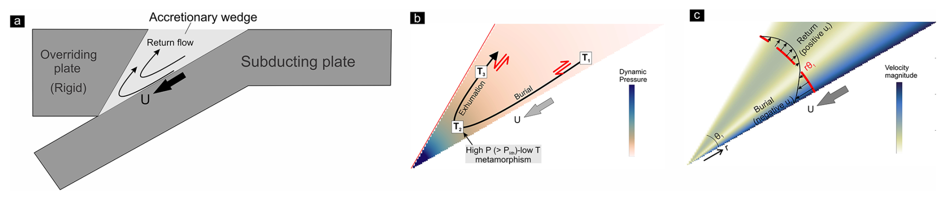
Figure 1(a) A schematic presentation of the return flow pattern in accretionary wedges. U: velocity at the wedge base. (b) Particle paths in the ideal corner flow within a wedge. The particles undergo the following sequential events: (1) burial in the time interval between T1 and T2; (2) high P-low T metamorphism at T2, where the total pressure (P) exceeds the lithostatic pressure (Plith), and finally, (3) return flow-driven exhumation in the time interval between T2 to T3. Note that the wedge develops opposite shear senses in the lower and upper parts. (c) Velocity profile across the wedge. Negative and positive values of the radial velocity component (ur) indicate burial and exhumation, respectively. θ1: wedge taper angle. r: distance from the wedge tip.
2.1 Basic premises
The present theoretical model is developed in the premises of downward-tapering accretionary wedges, which has been extensively used in earlier theoretical models (Cloos, 1982), analogue experiments (Luján et al., 2010) and numerical simulations (Pusok et al., 2022; Yamato et al., 2007). To simplify the theoretical treatment, the wedge is assumed to terminate at a fixed-point S, located at a depth of about 40 km (S-point boundary condition of Willett et al., 1993) (Fig. 2a). This is a limitation in our model setup, as the wedges in subduction zones can describe a narrow opening at their base, allowing a small fraction of sediments to be transported to mantle depths (Agard et al., 2009; Guillot et al., 2009). Traditionally, researchers have modelled accretionary wedges using Coulomb materials, primarily to analyze their mechanical stability as a function of the taper angle (Dahlen et al., 1984; Dahlen, 1990). This modelling approach is, however, applicable for shallow-crustal deformations. Below the brittle-ductile transition, at middle and lower crustal depths, viscous processes dominate in the wedge deformations (Mannu et al., 2016; Pavlis and Bruhn, 1983), and thereby demand a viscous rheological approach. To capture the exclusive effects of viscous wedge kinematics, our theoretical treatment excludes the additional influence of gravity that can arise due to the density contrast between the wedge and the overriding plate. In natural settings, however, buoyancy forces arising from density differences can also act as additional factor in driving the upward velocity of crustal blocks, especially at sub-crustal level (Ernst et al., 1997; Maiti et al., 2020; Schmalholz and Schenker, 2016). Also, we consider Newtonian viscous rheology to develop the present theoretical model. This linear rheological approximation is evidently simplification of the natural rheological settings that generally show a power-law creep behavior (Ranalli, 1995). In addition, their viscosity can vary with depth. However, it has been shown previously that the non-linearity of the rheology plays little role in the first-order kinematics of a corner flow (Ribe, 2015, 2018).
In the CF model of Cloos (1982), the upper bounding plate of the wedge (i.e., the overriding plate, hereafter abbreviated as OP) is considered rigid and held fixed, and the lower bounding plate (i.e., the subducting plate, hereafter abbreviated as SP) moves downward with the velocity vector oriented parallel to the wedge boundary (Fig. 1a). However, our theoretical modelling also considers a non-parallel component of slab velocity with rigid or deformable overriding plate. The subducting slab movements towards the OP and the ocean are considered to represent the slab advance and slab rollback kinematics, respectively. We simplify this theoretical approach assuming that the slab undergoes translational motion without any along slab gradient of the linear subduction vector. Our model also only considers the flow in the vertical plane perpendicular to the trench axis, and does not consider any trench-parallel flow in the wedge.
2.2 Rigid overriding plate model
The 2D accretionary wedge model is represented by a triangular domain of linearly viscous (μ1) materials, sandwiched between a SP and an OP. The wedge walls converge to each other downward, forming a taper angle θ1 (Fig. 2a, b). The rigid OP is held fixed, and the wedge base is subjected to a velocity U, obliquely to the wedge-subducting plate interface at an angle ϕ (positive anticlockwise; Fig. 2a, b). The slab-parallel component of U is the subduction velocity, Us, and its horizontal component represents the slab migration velocity, Um. In the following discussions, we use the term subduction obliquity (ϕ) to define the non-parallel component of slab velocity (measured in the trench axis-perpendicular vertical plane), which is different from the term generally used to describe the angular relationship of the convergence velocity vector with the trench line in the horizontal plane (McCaffrey, 1992). Positive and negative values of ϕ represent slab rollback and advance, respectively in this theoretical treatment. We consider no-slip boundary conditions at the two wedge walls, and also assume that the wedge undergoes no volume loss or material accretion during the deformation. A Cartesian frame xy is chosen with origin at the S-point of the wedge, with the x and y axes oriented in horizontal and vertical directions, respectively, as shown in Fig. 2b. The SP dips at angle α with respect to the horizontal surface. Considering our focus on the flow field in a triangular region, we choose a polar coordinate system for the theoretical analysis, similar to previous CF studies (Cloos, 1982; Moulas et al., 2021). The origin of the coordinate frame is set at the S-point, where r and θ represent the distance from the wedge tip (S-point) and the angular distance (positive anticlockwise) measured from the bottom wedge boundary respectively. The instantaneous velocity field within the wedge can be expressed in terms of polar coordinates (r, θ) as:
where ur and uθ are the radial and tangential velocity components, respectively and ψ is the stream function. Assuming negligible inertial forces and mass conservation, the stream function ψ for a 2D viscous flow satisfies the biharmonic equation:
Applying the boundary conditions in the present problem, we obtain the following relations:
These boundary conditions require that ψ is proportional to r everywhere in the wedge domain, including its boundaries. The stream function can be thus expressed as,
Substituting ψ in Eq. (2), we find:
where the primes denote the order of differentiation on f. The solution of Eq. (6) follows:
where A, B, C and D are four constants, which need be solved using four equations. Substituting f in Eq. (5) and putting the derivative expression in Eq. (1) we get:
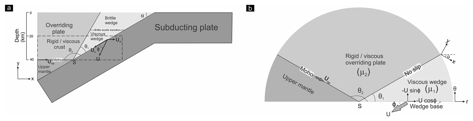
Figure 2(a) Schematic diagram of the tectonic setting considered for the present theoretical treatment. The subducting plate, dipping at angle α, moves downward obliquely at an angle ϕ to the bottom boundary of the wedge. Dashed rectangle demarcates the region of interest in this study. (b) Theoretical model setup in polar coordinate system (r, θ). The wedge and the overriding plate describe taper angles of θ1 and (θ2−θ1), respectively. μ1: wedge material viscosity. The overriding plate is considered either rigid or deformable (viscosity μ2). See text for details.
Putting θ=0, and θ1 in Eq. (8) and comparing the resulting expression with the boundary conditions of Eqs. (3), and (4), it follows
The solutions of Eq. (9) are:
2.3 Deformable overriding plate model
To deal with the kinematic problem of accretionary wedges with deformable OP, we solve the velocity field in two corner regions (Anderson and Davis, 1993; Moulas et al., 2021) representing the wedge and the overriding plate (Fig. 2b). The theoretical model setup is considered same as in the rigid OP model, except that the present case incorporates an additional corner region with viscosity μ2 in the hanging wall of the wedge, representing the viscous crust of the overriding plate (Moulas et al., 2021). The OP–wedge viscosity ratio is denoted as . The wedge and the overriding plate have taper angles θ1 and θ2−θ1 respectively. In this analysis, we also impose a velocity (Uop) at the Moho of the overriding plate. Several authors have, however, argued that the cold upper mantle beneath the OP in proximity to the subduction zone is stationary and does not participate in the surrounding mantle corner flow (Lee and Kim, 2023; van Keken and Wilson, 2023). The presence of this cold region is attributed to mechanical decoupling at the interface between the forearc mantle and subducting slab (Abers et al., 2017; Wada and Wang, 2009). Hence, in most of our theoretical analyses, we consider Uop to be equal to zero.
Following a similar approach of Anderson and Davis (1993), and Moulas et al. (2021), we choose two stream functions: ψ1 and ψ2 for solving the velocity fields in the wedge and the OP crustal domains, respectively. Similar to the theoretical treatment in Sect. 2.2.1, the two stream functions are expressed in the form:
where,
Ai, Bi, Ci, Di (i=1, 2) represent eight constants. To find the velocity fields in the wedge and OP regions, we need to evaluate the eight constants, which evidently demands eight boundary conditions. At the subducting plate-wedge interface, the two velocity boundary conditions in terms of polar coordinates (r, θ) is:
Velocity boundary conditions at the Moho in the overriding plate give,
Assuming no slip at the wedge–OP interface, the velocity continuity across this interface leads to:
where the subscripts “wd” and “op” refer to the wedge and the overriding plate. The total normal stress as well as the shear stress must be continuous across the wedge–OP interface. The deviatoric stress tensor τij is expressed in polar coordinates (r, θ) as,
where μi (i=1, 2) denotes the viscosities of the two corner regions. The total stress tensor σij is given by:
where P is the total pressure, given by the sum of static pressure (Ps) and dynamic pressure (Pd). As Ps has no implications in the present corner flow solution, P=Pd, which can be determined from the stress-equilibrium equation in the radial direction,
Using the boundary condition Pd=P0 at r=∞, we find the integration constant, which appears after solving the differential equation in Eq. (18). P0 is set as 0 in the given problem, assuming that the dynamic pressure becomes zero at infinite distance away from the S-point of the wedge. The choice of P0, however, does not qualitatively change the velocity or strain fields either in the wedge or the overriding plate.
The normal components (τrr and τθθ) of the deviatoric stress tensor (Eq. 16) in the present setting are zero as there is no extension along as well as across the radial direction, i.e., . This wedge kinematics results because the velocity components at any point (r, θ) within the wedge are independent to r and hence, the radial directions are the directions of the flow apophyse across the wedge. Consequently, the total normal stress (Eq. 17) perpendicular to the wedge-overriding plate interface equals the dynamic pressure Pd. The stress continuity across the interface requires (Moulas et al., 2021),
Equations (13), (14), (15) and (19) provide the eight boundary conditions, which are utilized to solve the eight unknown constants in Eq. (12). Their expressions are provided in the Appendix A. Using these constants we determine the two stream functions (ψ1 and ψ2) and find the velocity fields in the polar coordinates (r, θ) at the two corner regions from Eq. (1). It is noteworthy that for given U and Uop, the velocity field is dependent on θ1, ϕ, θ2 (=180° − α), and μr (=μ2μ1) in an accretionary wedge with deformable OP (see Eqs. A6–A13 in Appendix A). This is in contrast to the case with rigid and fixed OP, where the velocity field is entirely dependent on the first two of the aforementioned factors, as discussed in Sect. 2.1. The velocity components determined in the polar coordinate system is converted to the Cartesian frame xy using the following transformation:
3.1 Return flux
Return flow in a downward-tapering wedge is considered to be one of the most effective exhumation mechanisms to explain the high P- and low T rock assemblages in the accretionary wedges or subduction channels (Agard et al., 2009; Cloos and Shreve, 1988; Yamato et al., 2007). For a quantitative analysis of the return flows in a wedge, we introduce a non-dimensional parameter, termed as return flux (FR), which is defined as the ratio of the volumetric rate of materials being returned to that of materials undergoing burial at an instant within the wedge. This parameter accounts for burial and exhumation within a wedge driven by slab-parallel subduction, as well as additional contributions arising from wedge squeezing (or unsqueezing) in cases of non-parallel subduction. In the polar coordinate system under consideration, positive and negative values of the radial component (ur) of the velocity vector indicate the rates of return and burial of wedge materials, respectively (Fig. 1c). For the present simplified 2D problem, we assume the velocity field remaining uniform along the trench, and express FR as:
where N1 and N2 represent number of areal elements of regions with positive and negative radial velocity (ur) within the wedge. High FR implies a condition of strong return flows (hence exhumation), whereas zero or low FR indicates either no return flows or a kinematic condition in which the return flows are deflected towards the overriding plate (for deformable overriding plate). A FR=1 condition indicates that the wedge maintains volume conservation by allowing return flows to occur in volumes equal to those by burial-driven flows at any instant. For slab-parallel subduction, FR can vary between 0 and 1. We, thus, choose a value of 0.5 (middle between the two extremities) as a reference to qualitatively express the return flow strength (strong vs. weak) in wedges. An addition of bulk horizontal shortening in the wedge due to an oblique U condition would result in an extra volume of wedge material extrusion (return), leading to a FR>1 condition. For the FR calculations, we discretize the wedge into 1000 equal small arc elements at r=10 km. Each arc covers an angle of . Since the velocity field in the corner flow solution is independent of r, FR does not depend on the choice of r. The infinitesimal strain field at a point inside the wedge or the OP can be expressed by a stretching-rate tensor (Means et al., 1980) in polar coordinates (r, θ) as:
The eigenvalues and eigenvectors of the stretching-rate matrix (Eq. 22) give the values and the orientations of maximum and minimum instantaneous stretching axes, ISAmax and ISAmin respectively. The vorticity w in polar coordinates (r, θ) can be written as:
For wedges with deformable OPs, the vorticity in the wedge and the OP is determined by replacing C, D of Eq. (18) by C1, D1 and C2, D2 respectively. Equation (18) shows that the vorticity is inversely proportional to the distance from the tip of the wedge. For our analysis, the vorticity at any point (r, θ) is normalized by the factor ). Positive and negative values of the normalized vorticity parameter () indicate anticlockwise and clockwise rotation, respectively. As mentioned in the preceding Sect. 2.2, the wedge kinematics and that in the overriding plate depend on several factors (e.g., ϕ, μr). We, however, present a parametric analysis to show the impact of the most influential factors in controlling the velocity and strain fields in the wedge. The present analysis covers a depth range between 20 and 40 km (Fig. 2a). Unless mentioned otherwise, we discuss in the foregoing sections the results for the case of accretionary wedges with a taper angle of 30° and viscosity of 1019 Pa s (Behr and Becker, 2018), keeping the OP fixed (i.e., Uop=0). The OP-wedge viscosity ratio (μr) is varied between 1 to 104, implying that our modelling covers a weak (∼1019 Pa s) to an extremely strong (∼1023 Pa s) overriding plate condition in the present analysis. Such a wide range of the OP viscosity is chosen considering that the strength of crustal materials can vary widely depending on the composition and thermal structure, among several other factors. According to available estimates, a cold, anhydrous, mafic overriding mass is found to be strong with viscosity Pa s, whereas a warm, hydrous, quartz-rich one is significantly weak with viscosity (Shinevar et al., 2015). Our modelling considers a subduction dip angle of 30°, which is within the ranges of mean shallow dips determined from several subduction zone transects (Hu and Gurnis, 2020; Lallemand et al., 2005). The wedge base is subjected to a velocity (U) of 3 cm yr−1, as observed in many modern-day subduction zones (Doglioni et al., 2007). In natural settings, however, faults and shear zones may localize at the subducting slab-wedge contact, and U can thus effectively vary from a few millimetres to centimetres per year.
3.2 Parametric analysis
3.2.1 Role of subduction obliquity
Accretionary wedges with SP movements parallel to the basal wedge boundary (ϕ=0°) against a fixed rigid OPs localize return flows close to the upper boundary (Fig. 3a-i). FR calculated from Eq. (21) is 1, implying that the crustal materials undergoing burial are potentially recycled back to the surface in the same quantities at any instant. The analytical solutions indicate that the degree of subduction obliquity strongly controls the flow patterns in wedges. Slab advance kinematics (i.e., negative ϕ) greatly facilitates the return flux, e.g., FR=4.56 when °. The wedge materials extrude at high velocities (∼U) along the inclined wedge roof (Fig. 3b-i), and may even locally exceed the subduction velocity for high negative ϕ (°). In contrast, the slab rollback kinematics (i.e., ϕ is positive) significantly reduces FR, dropping it to zero for considerable rollback rates. At extremely slow rollback (), the wedge still produces weak return flow. However, at relatively higher rollback velocities, all the wedge materials are buried at high rates, which may locally exceed the subduction velocity (Fig. 3c-i, d-i).
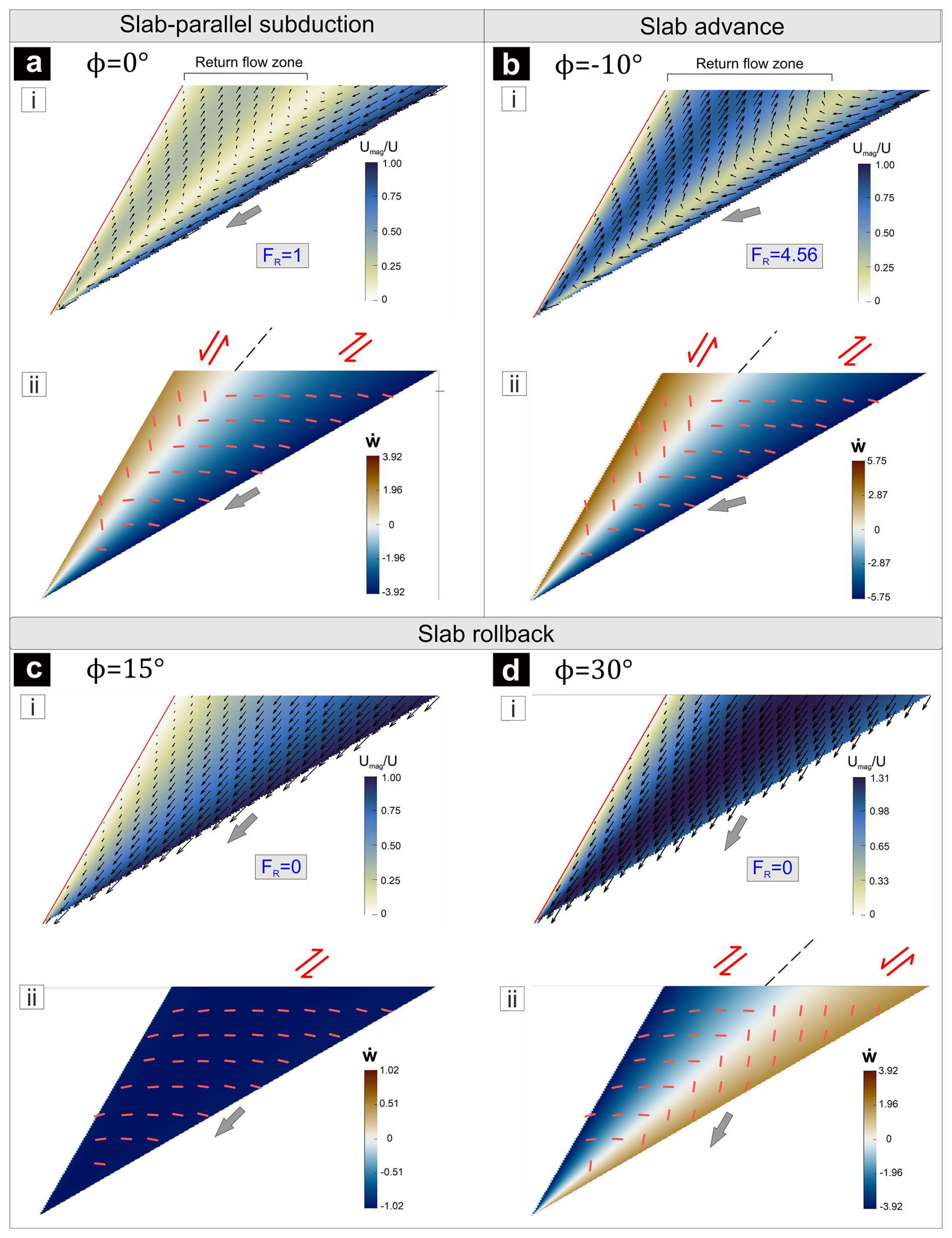
Figure 3Velocity and vorticity fields within wedges with rigid walls in tectonic settings with varying subduction obliquities (ϕ). θ1=30°, and α=30°. Umag: flow velocity magnitude and : a normalized vorticity parameter. Short red lines mark the orientations of the minimum instantaneous stretching axes (ISAmin). Note that addition of a slab advance component substantially multiplies the return flux (FR), whereas slab rollback lowers FR.
The subduction obliquity also controls the viscous strain distributions in the wedge beneath a rigid OP. When ϕ has negative, zero or extremely low positive values (), the wedge flows show a vorticity sense reversal, from negative (clockwise, thrust-sense shear) in the basal part to positive (anticlockwise, normal-sense shear) in the roof (Mandal et al., 2002). The upper part of the wedge is characterized by vertical to sub-vertical ISAmin axes (Fig. 3a-ii, b-ii). The field of normal-sense shear in the roof region progressively shrinks with increasing ϕ, and vanishes for high slab rollback velocities, corresponding to . For a relatively large ϕ value (), the basal part of the wedge produces normal-sense shear with sub-vertical ISAmin axes (Fig. 3d-ii). Conditions in the range , in contrast, produces thrust-sense of shear in the entire wedge domain (Fig. 3c-ii).
3.2.2 Control of overriding plate wedge viscosity ratio
Our analytical solutions indicate that, in case of a deformable OP, the viscosity ratio, μr can strongly influence the flow pattern in the wedge. μr≥103 yields the first order flow pattern similar to that observed in the rigid OP setting. For μr=103, the ϕ=0° subduction condition gives rise to a high return flux (FR=0.7), which is, however, less than that (FR=1) in the equivalent rigid OP setting (Fig. 4a-i). Negative ϕ leads to a condition of exceptionally strong return flux (e.g., FR=3.43 when °), where the return flows attain high velocities (0.7U), comparable to the subduction rates (Fig. 5a-i). However, lower μr () weakens the confinement of viscous flows within the wedge, allowing the flows to become distributed in the OP region. In such conditions, the materials lying beneath the wedge-roof flow towards the overriding plate, instead of returning back towards the surface (Figs. 4b-i, c-i, 5d-i). This kinematic transformation results in significant weakening of the return flux within the wedge. For ϕ=0 and −10°, a decrease in μr from 103 to 102 drastically reduces FR from 0.7 to 0.06, and 3.43 to 0.55, respectively. At μr=10, the wedge hardly develops any return flux (Fig. 4c-i). For considerable slab rollback velocity (positive ϕ), similar to the case with rigid overriding plate, FR drops to zero for all the viscosity ratios (Fig. 5b-i, c-i, e-i, f-i). The slab rollback process facilitates the burial rates of wedge materials, which may locally exceed the subduction velocity. The condition of relatively low μr (≤102) sets in trench-ward movement of the overriding plate during the slab rollback (Fig. 5e-i, f-i).
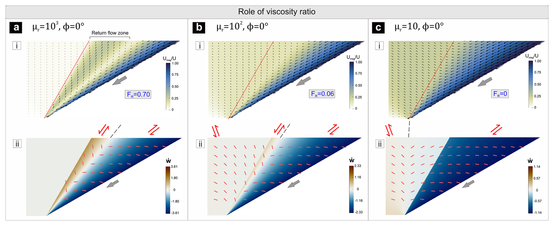
Figure 4Velocity and vorticity fields in wedges with deformable wall settings undergoing slab-parallel subduction. θ1=30°, and α=30°. Decrease in wall to wedge viscosity ratio (μr) lowers FR.
In a mechanical condition with μr=103, negative, zero or small positive ϕ values result in reversal of shear across the wedge, showing a transition of shear sense from thrust in the basal part to normal beneath the wedge roof (Figs. 4a-ii, b-ii, 5a-ii, d-ii). For a given ϕ, decreasing μr causes the normal-sense shear field to shrink, and finally disappear when μr is extremely low (∼10), and the whole wedge is dominated by thrust-type shear (Fig. 4c-ii, see also Sect. S2 in the Supplement). For , the OP undergoes deformations in response to the shear stress generated at the wedge-slab interface (Figs. 4b-ii, c-ii, 5d-ii, f-ii). The addition of slab advance kinematics induces strong sub-horizontal shortening, combined with thrust shear in the OP. On the other hand, the slab rollback, as shown earlier for the wedge with rigid OP, the entire wedge is affected by thrust shear when ϕ is neither extremely low nor high (Fig. 5b-ii, e-ii). In contrast, higher ϕ conditions develop normal shear with sub-vertical ISAmin axes in the trench-ward side of the wedge (Fig. 5c-ii, f-ii). For moderate to low viscosity ratios (), the slab rollback is associated with considerable sub-horizontal extension (ISAmax) in the overriding plate, away from the wedge (Fig. 5f-ii).
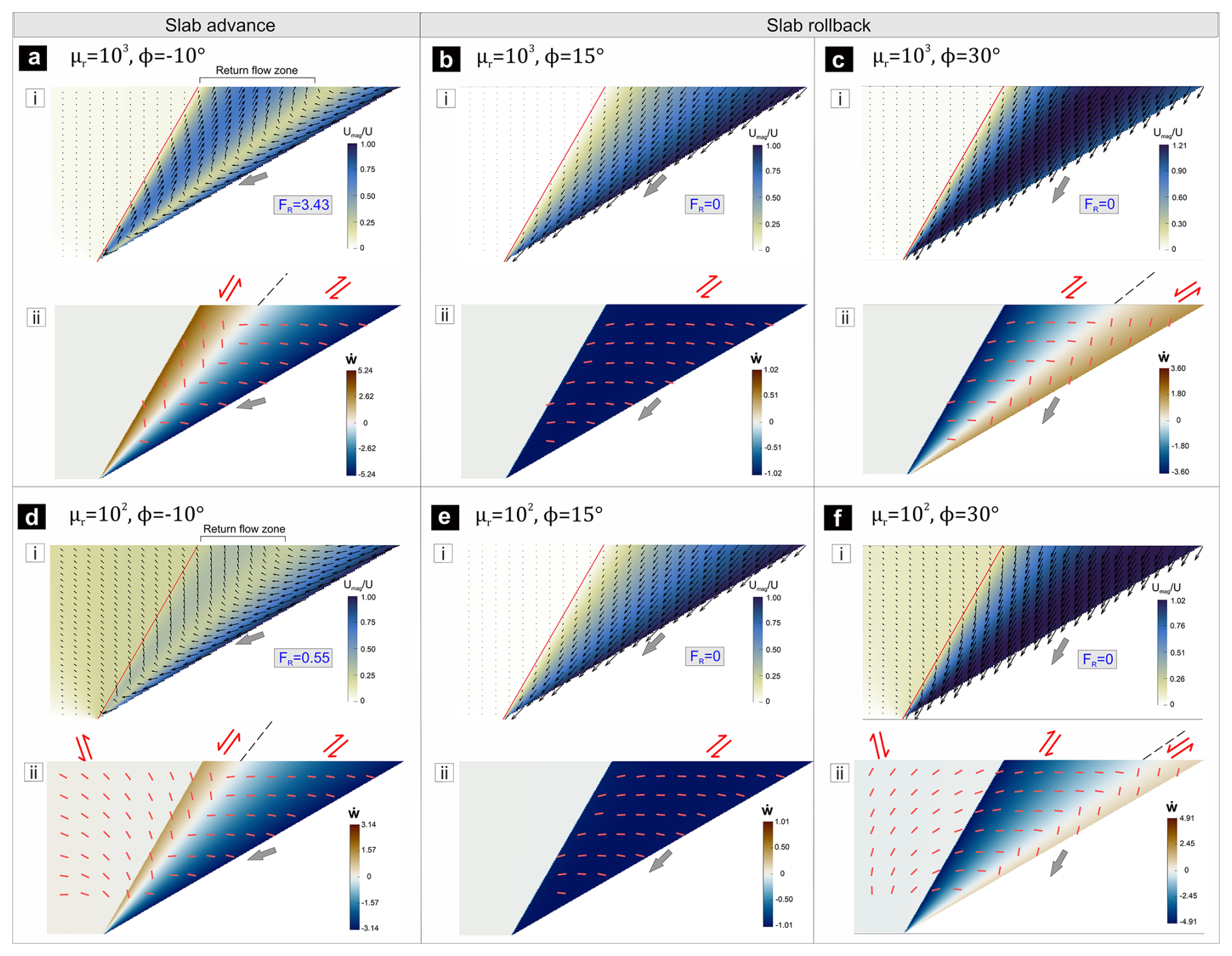
Figure 5Effects of subduction obliquity (ϕ) and viscosity ratio (μr) on the velocity and vorticity fields in wedges. θ1=30°, and α=30°.
3.2.3 Influence of taper angle
Accretionary wedges can be narrow or wide, depending on the sediment influx and outflux of sediments into or from the wedge (Clift and Vannucchi, 2004; Cloos and Shreve, 1988) and the effects of other factors, such as subduction geometry (Pusok et al., 2022). Our analytical solutions show that increasing θ1 strengthens the return flux in a wedge (Fig. 6a-i, b-i, c-i). For ϕ=0° and μr=102, an increase in θ1 from 15 to 120° increases FR from 0 to ∼1. Narrow wedges with ° do not produce any return flows (Fig. 6a-i) when μr is low to moderate (). In such conditions, the flows fails to redirect wedge materials back to the surface as they are strongly deflected towards the OP, which becomes more pronounced when the plate convergence involves slab advance (see Sect. S1). This kinematics implies that the wedge–OP interface will progressively migrate rearward and result in distortion of the initial wedge geometry. Such an “unstable” state of wedges with low taper angles, and weak walls has been discussed in detail by Moulas et al. (2021).
Large-taper wedges (θ1=120°) develop thrust shearing in a bi-vergent configuration, as illustrated in Fig. 6c-ii. The oppositely verging thrust-shear zones are separated by a zone of normal-sense shearing. In contrast, narrow wedges with moderate to low μr () never produce a condition of shear reversal, but allow the OP to accommodate considerable deformations (Fig. 6a-ii).
3.2.4 Role of the OP velocity
The overriding plates often experience a trench-ward velocity (Uop) due to far-field tectonic stresses or drag of the underlying mantle flows (Cerpa and Arcay, 2020; Jarrard, 1986; van Dinther et al., 2010). We use the present analytical solutions to investigate the effects of Uop on wedge flows. In case of no slab rollback, addition of Uop strengthens the convergence within the wedge, resulting in extrusion of the wedge materials from its roof regions to the surface (Fig. 6d) (Nettesheim et al., 2018). For relatively lower rollback velocities (e.g., ϕ=15°), the wedge shows curvilinear flow trajectory with upward convexity (Fig. 6e), as observed in some of the numerical models (e.g., Candioti et al., 2021), implying that crustal materials under a steady state kinematic state of the wedge would be extruded for a small extent, and then recycled back to deeper regions. High rollback velocities, in contrast, facilitate the burial process of wedge materials with the subducting slab, allowing their little or no subsequent uplifts (Fig. 6f).
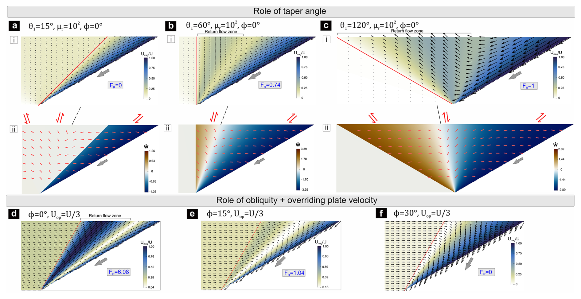
Figure 6(a–c) Influence of taper angle (θ1) on the kinematics of wedges in settings undergoing slab-parallel subduction. (d–f) Effect of trench-ward moving overriding plate movement () on the flow patterns of wedges: μr=102, and α=30°.
3.2.5 Effects of subduction dip
For a constant dip of the wedge–OP interface, decreasing slab dips give rise to increasing taper angles, which in turn facilitate the return flux (FR) within the wedge. A steep dip of the wedge–OP interface yields higher extrusion rates (higher vertical component of velocity in Cartesian xy-frame) of the extruding wedge materials (see also Sanhueza et al., 2022). However, steeply dipping slabs generally exhibit high rollback velocities (hence increase in ϕ) due to slab pull force (Stegman et al., 2010), which in turn affect the wedge kinematics. From a dynamic point of view, lower subduction dips allow the convergent system to transmit higher stresses to the wedge and the overriding plate, and give rise to intense deformations in the forearc region (Chemenda et al., 2000; Guillaume et al., 2009).
The analytical solutions described above provide the instantaneous kinematic behaviour of a wedge for a given geometry and under a specific set of boundary conditions. To validate the analytical results, and evaluate the wedge kinematics in finite timescale, a series of scaled laboratory experiments were performed. The experiments allow us to decipher the evolution of velocity fields in wedges with deformable walls and varying boundary kinematics, as described in the preceding sections.
4.1 Model setup
The model accretionary wedge was made up of polydimethylsiloxane (PDMS), a Newtonian viscous fluid (viscosity ∼104 Pa s) at strain rates below 10−2 s−1, and a density of ∼965 kg m−3 (Weijermars, 1986). The wedge was ∼ 5.6 cm thick, and had a taper angle of 45° Fig. 7a). One set of models had overriding plates of high-viscosity (∼ 106 Pa s) modelling clay-PDMS mixture (4:1 ratio), while the other set had overriding plates of a relatively low-viscosity (∼ 105 Pa s) mixture of the same materials (1:4 ratio). The wedge had a basal dip of 45°, and a vertical boundary with the overriding plate. The model had a length of 20 cm in y direction, and its upper surface was set free. This configuration develops a deformation regime close to plane strain condition with negligible deformation along the y direction, especially in the earlier stages of the experiments. The deformation box walls were lubricated with soap to reduce the friction between the viscous materials and glass walls.
In a reference frame fixed to the base of the deformable wall, a velocity was applied either parallel or oblique to the wedge base to simulate slab-parallel subduction and slab advance/rollback kinematics, respectively (Fig. 7b, c) (details of the kinematic boundary conditions provided in Sect. S3). During an experimental run, photos of the model vertical section were taken at regular time intervals, which were post-processed to obtain incremental displacement fields using the PIVLab (Thielicke and Stamhuis, 2014), an open-source image correlation software run in MATLAB.
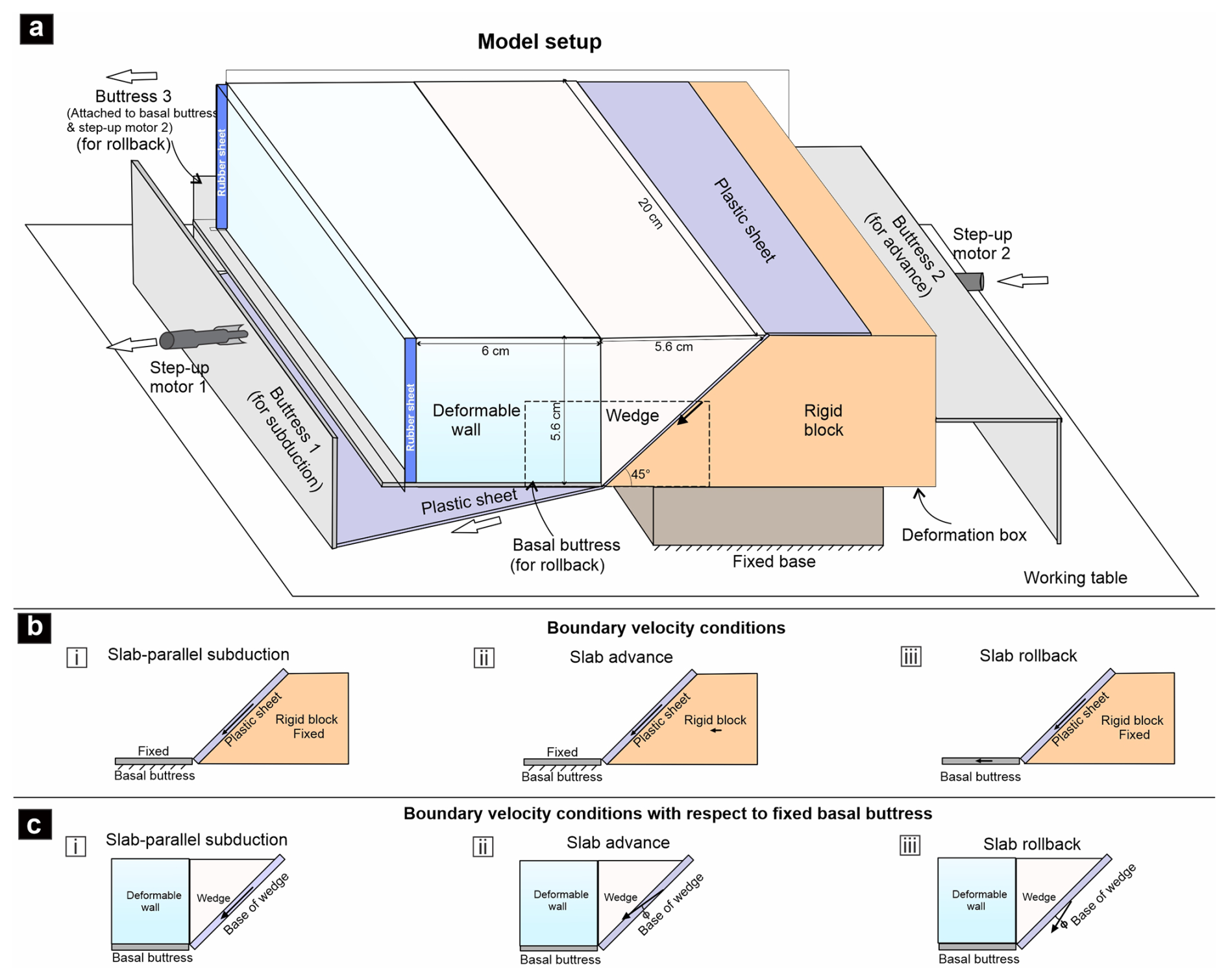
Figure 7(a) Laboratory model setup used for wedge experiments (details provided in the text). Dashed rectangle shows the region of interest. (b) Velocity conditions imposed at the model boundaries to simulate slab-parallel subduction, slab advance, and slab rollback in the models. (c) Boundary velocity conditions with respect to a fixed basal buttress.
4.2 Scaling
Analog models were scaled to natural settings to obtain length, dynamic, rheological, and kinematic similarities (Schellart and Strak, 2016; Ramberg, 1981). A length ratio lr () of was used in the model. Under this scaling, the 5.6 cm thick wedge model represented a ∼40 km thick viscous accretionary wedge. We, however, limit our analysis to the lower 20 km (equivalent to ∼3 cm in model) part of the wedge as natural accretionary wedges mostly exhibit brittle deformation in the upper crustal regime. The model viscous wedge was made thicker to minimize the mechanical influence of the model's upper “free surface” in the region of interest (i.e., between a depth of 20 to 40 km), especially during the early stages of experiments. The experimental results of the whole model wedge is provided in Sect. S4.
The subduction in all the models was driven by moving a plastic sheet at a velocity (Vmodel) of 0.7 mm min−1 beneath wedge base, which ultimately passed through a slot beneath the model (Fig. 7). Considering a basal velocity (Vnature) of 1 cm yr−1 in geological settings, we obtain a velocity scaling ratio (Vr) of ∼36 792, and a time ratio () of . This relatively lower value of V was chosen as a part of the subduction velocity may be partitioned in faults or shear zones at the wedge-subducting plate contact. However, the analytical results suggest that the choice of V hardly influences qualitatively the flow patterns in CF settings. Assuming a depth-averaged density of 2800 kg m−3 for accretionary wedge rocks, the density scaling ratio ρr was set at ∼0.36. As the experiments were run under normal gravity conditions, the scaling ratio for gravitational acceleration (gr) is 1. These scaling factors yields a viscosity scaling ratio, . Our model wedge is thus scaled to a natural accretionary wedge with a relatively higher depth-averaged viscosity of Pa s. However, for a given OP–wedge viscosity ratio, this absolute wedge viscosity (μ1) hardly influences the corner flow pattern, as extrapolated from the analytical solutions. μ1 can only play a role in determining the intensity of gravity-driven flows that occur during later stages of wedge deformation.
4.3 Experimental results
4.3.1 Slab-parallel subduction (ϕ=0°)
This model setting (ϕ=0°) develops strong return flows in the wedge when the wall to wedge viscosity ratio is large (μr≈102) (Fig. 8a-ii). Materials close to the moving wall are dragged down, while materials in the rear side are uplifted. During early stages of the experiments, the maximum vertical velocity (vmax) across the wedge is about 0.5U, where U is the basal velocity. A lower viscosity ratio (μr≈10) results in the return flow to strongly deflect towards the overriding plate (Fig. 9a-ii), and substantially lowers vmax within the wedge to 0.25U. The deflected flow induces considerable deformations and uplift (at rates ∼0.23U) in the wall close to the wedge. These flow patterns are similar to the analytically predicted velocity fields (Figs. 8a-i, 9a-i), especially close to the wedge corner region. Away from the corner, the velocity vectors in the return flow become slightly steeper than those predicted by the theoretical solution. This small difference arises from the influence of the “free upper surface”, which is located at a finite distance above the corner in laboratory models, whereas the analytical model assumes a wedge that extends infinitely upward from the corner. In μr≈10 experimental models, the deflected return flows progressively distort the wedge geometry by forming a bulge into the wall near the corner region (Fig. 9a-ii). This bulging results from dynamic pressure localization at the wedge corner, which is strong enough to deform the relatively weak overriding plate (see Sect. S1). However, the wedge grossly retains its initial wedge geometry in models with relatively strong overriding plates (μr≈100). These experimental findings are in agreement with the numerical models of Moulas et al. (2021), showing that the corner geometry becomes unstable with lowering of μr.
.
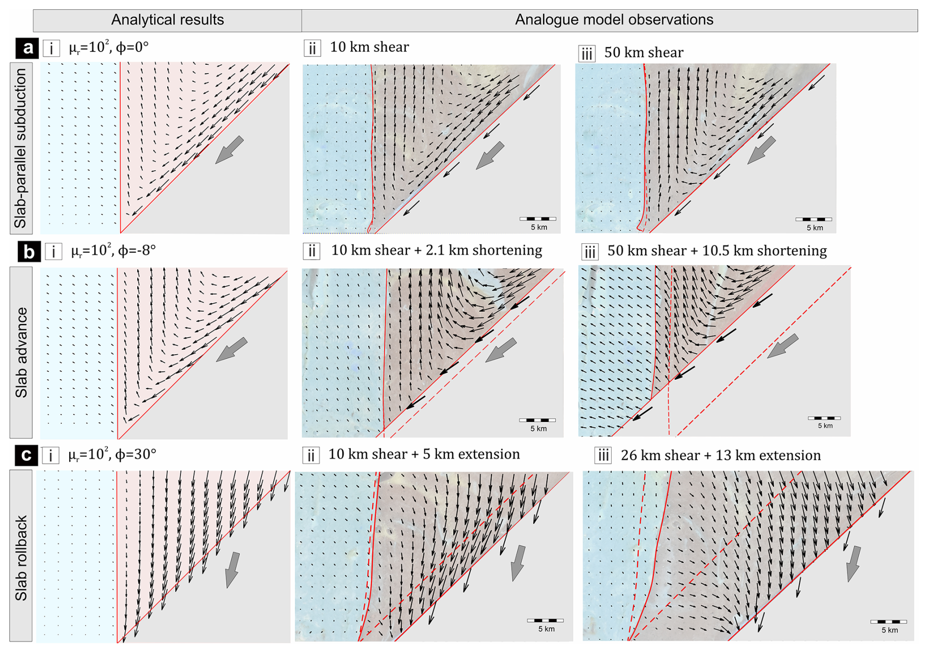
Figure 8Evolution of wedge kinematics in μr≈102 experimental models: (a) slab-parallel subduction (ϕ=0°), (b) slab-advance (°), and (c) slab rollback (ϕ=30°) settings. Left panel: Instantaneous velocity field predicted from the analytical solutions with similar setups shown as a reference. Central (ii), and right (iii) panels: Model flow patterns (in a reference frame fixed to the base of the deformable wall) at two different stages of the experiments. The solid and dashed red lines demarcate the present boundaries of the wedge and their initial positions, respectively
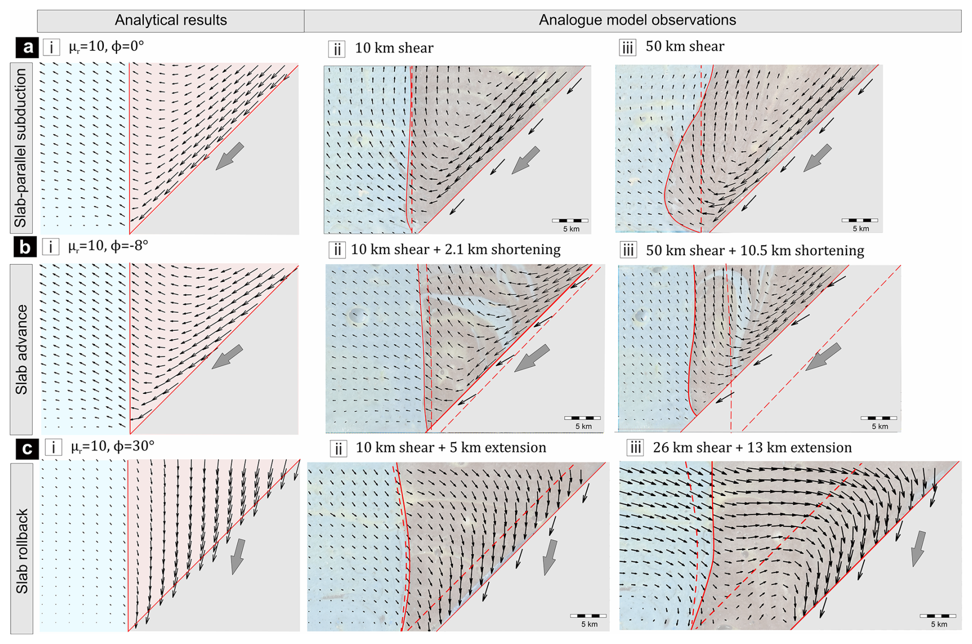
Figure 9Evolution of wedge kinematics in μr≈10 experimental models: (a) slab-parallel subduction (ϕ=0°), (b) slab-advance (°), and (c) slab rollback (ϕ=30°) settings. Left panel: Instantaneous velocity field predicted from the analytical solutions with similar setups shown as a reference. Central (ii), and right (iii) panels: Model flow patterns (in a reference frame fixed to the base of the deformable wall) at two different stages of the experiments. The solid/dashed red lines same as in Fig. 8.
With progressive subduction, the model wedge develops an upward-convex topography at the wedge surface with steep slope at the wedge front (Figs. S3a-ii, S4a-ii in the Supplement). The topography stops growing in the later stages of the experiments, and eventually gives rise to gravity-driven flow from the rear region toward the wedge front. In this stage, the concurrence of extrusion flows at depth, and their subsequent collapse in the shallow region lead to a closed flow path in the upper parts of the wedge (Figs. S3a-ii, S4a-ii), as observed in several previous analytical (e.g., Emerman and Turcotte, 1983; Platt, 1993), and numerical models (e.g., Van Dinther et al., 2012; Allemand and Lardeaux, 1997; Yamato et al., 2007). The effect of this closed flow pattern extends even to the bottom 20 km of the wedge in the later stages of experiments (Figs. 8a-iii, 9a-iii). For low μr, the trenchward gravity-driven flow within the wedge also drags the overriding-plate material, resulting in change in the return-flow kinematics from earlier stages of the experiment. This effect is especially evident away from the wedge corner, where the previously sideways-deflected return-flow vectors reorient toward a more vertical orientation (compare Figs. 9a-ii and 9a-iii). At this stage, the wedge–OP interface migrates rearward at depth close to the corner, but migrates towards the wedge front away from the corner, resulting in progressive reduction in taper angle of the wedge (Fig. 9a-iii).
In natural settings, surface erosion and infilling of sediments that can smoothen out the topographic slope in the wedge, and are thus expected to reduce the late-stage gravity-driven flow. We ran an additional set of experiments with μr≈10 by adding new materials to the evolved wedge surface after 45 km shear movement, restoring grossly its horizontal initial orientation (see Sect. S5, Fig. S5). Further shearing in this modified model setting gives rise to return flows strongly deflecting towards the overriding wall, similar to that observed in the initial stage of the experimental run.
4.3.2 Slab advance (°)
Slab advance kinematics facilitated the uplift process at rapid rates in the rear part of the wedge, as predicted by the analytical solutions (Figs. 8b, 9b). During the initial stages, the maximum extrusion velocity vmax within the wedge attains values of ∼0.8U, and ∼0.4U in the strong and weak overriding plate models, respectively (Figs. 8b-ii, 9b-ii). For lower μr, the strongly deflected return flows induce significant deformations and uplift (at rates ∼0.16U) in the overriding plate.
Progressive slab advancement leads to bulk horizontal squeezing of the wedge, driving the process of vertical extrusion. After 50 km of shear and 10.5 km of shortening, wedge materials at depth thus experience uplift at relatively high rates of ∼0.6U and ∼0.4U for high and low μr experiments, respectively (Figs. 8b-iii, 9b-iii). In the later stages of experiments, the advancing slab comes in direct contact with the overriding plate (Fig. 8b-iii), forcing uplift (at rates ∼0.13U) and deformation even in the stronger wall (μr≈102) of the wedge. For low μr, the wedge–OP interface is strongly deflected sidewise towards the overriding plate, and distorted near the corner (Fig. 9b-iii).
4.3.3 Slab rollback (ϕ=30°)
Slab Rollback facilitates burial of materials in the entire wedge, leaving return flows completely absent in the system. This experimental finding agrees with the analytical solutions (Figs. 8c, 9c). The downward flows during rollback cause progressive vertical subsidence, accompanied by bulk horizontal extension of the wedge. Low μr (≈10) model induces this extension to occur even in the weak overriding wall (Fig. 9c-ii).
With progressive rollback, the initial narrow geometry of the wedge undergoes significant modifications (Figs. 8c-iii, 9c-iii), but materials continue to flow down with maximum velocity in proximity to the moving wall. This flow pattern gives rise to a steep surface slope close to the moving wall (see Figs. S3, S4), which eventually triggers additional gravity-driven sub-horizontal flows of wedge materials from the rear to the frontal side in later stages of the experimental run. Effect of this sub-horizontal flow is also observed at the bottom 20 km of the wedge. This results in shallowing of the previously steep velocity vectors during the later stages (Figs. 8c-iii, 9c-iii). That effect is more prominent in models with lower μr, where the magnitude of negative dynamic pressure, which drives the corner-flow kinematics during rollback, is relatively less (see Sect. S1). In natural subduction zones, however, opening at the base of the wedge during slab rollback can lead to entrainment of the wedge materials into the mantle. In such cases, the flow pattern at the bottom parts of the wedge will differ from the results observed in our models with a rigid base.
4.4 Analogue and analytical model results: a synthesis
Both analogue experiments and analytical solutions suggest that the following parameters: slab obliquity (ϕ), overriding plate-wedge viscosity ratio (μr), wedge taper angle (θ1), and overriding plate velocity (Uop) largely determine the intensity of return flows in viscous accretionary wedges.
For slab-parallel subduction (ϕ=0°), a high μr () condition favours deep-crustal material extrusion, forming strong return flows in the rear side of the wedge (Figs. 4a, 8a). Lowering of μr () weaken the return flows, while facilitates lateral deflection of the extruding materials, resulting in intense deformations in the overriding plate (Figs. 4c, 9a). In contrast, slab advance (negative ϕ) leads to bulk horizontal shortening, resulting in enhanced vertical extrusion (Figs. 5a, d, 8b). Analogue model results show that after finite advance, the subducting slab comes directly in contact with the overriding plate, inducing significant uplift and deformation in the overriding plate, irrespective of μr. On the other end, slab rollback () promotes the burial process across the entire wedge without any return flow (Figs. 5b, c, e, f, 8c, 9c). Under a low μr condition, this rollback process can also induce extensional deformations in the overriding plate. Analogue model results further indicate that that gravity-driven flow may become important with progressive deformation of the low-viscosity wedge materials. Analytical solutions reveal that for low to moderate μr, wedges with small taper angles suppress return flows, while wider wedges facilitate it. Trenchward movement of the overriding plate also enhances the upward extrusion process.
The subduction settings with slab-parallel subduction, slab advance, or highly oblique () rollback results in reversal of shear sense across the wedge for moderate to high μr (Figs. 4a, 5a, c, d, f). However, the sense of shear remains unchanged in cases of low μr, or less-oblique rollback (Figs. 4c, 5b, e).
5.1 Conditions for return flows in viscous accretionary wedges
The analytical, and analogue model results discussed above suggest that the return flows in accretionary wedges, which play a crucial role in deep-crustal exhumation processes can occur under specific conditions. The role of each factor in setting the return flows is summarized in Fig. 10. It can be readily seen that appreciable return flows (FR>0.5) occur in the following conditions: little or no slab rollback (ϕ<5°), high overriding plate-wedge viscosity ratio (), and moderate to high taper angle (°). Wedges with large taper angles produce strong return flows, independent of the OP viscosity. Narrow wedges, i.e., low θ1 (e.g., 15°) become almost devoid of any focused return flows, unless the OP is rigid or has high viscosity (μr>103). A strong overriding plate accommodates little strains, forcing the viscous flows to localize within the wedge. Increase in μr thus promotes the return flux (Fig. 10b). The return flow is also facilitated by the slab advance (ϕ<0°), but countered by the slab rollback process in subduction zones (Fig. 10a). In presence of a stronger OP (), additional squeezing of the wedge during slab advance can lead to a FR>1 condition. These contrasting flow kinematics originate from the competing dynamics of two processes: dominance of a downward flow, induced by the subducting slab drag, and an upward flow, driven by a negative upward dynamic pressure gradient along the downward-tapering wedge (Fig. 1c). The first process enables the burial mechanism of the wedge materials, whereas the second process forces the materials to extrude up, setting in return flows. The analytical results suggest that deformable OP settings with high μr, low ϕ, and large θ1 develop strong negative upward dynamic pressure gradients along the wedge (Fig. S1), which leads to the generation of return flows. For small θ1, and low μr, dynamic pressure gradient across the wedge forces the return flow to deflect towards the wall (see Sect. S1). Progressive increase in ϕ lowers this pressure gradient and then reset its trend in the reverse direction (Fig. S2, see also Fig. 13). This finding predicts the absence of return flows in wedges where the slab rollback is active. Trench-ward OP motion also facilitates the extrusion process in a wedge (Fig. 6d). Other geologically relevant factors, which are excluded in the present study, such as presence of buoyant rocks, normal faulting, and erosion can promote return flows of deep-crustal materials in accretionary wedge materials (see Warren, 2013, for a review).
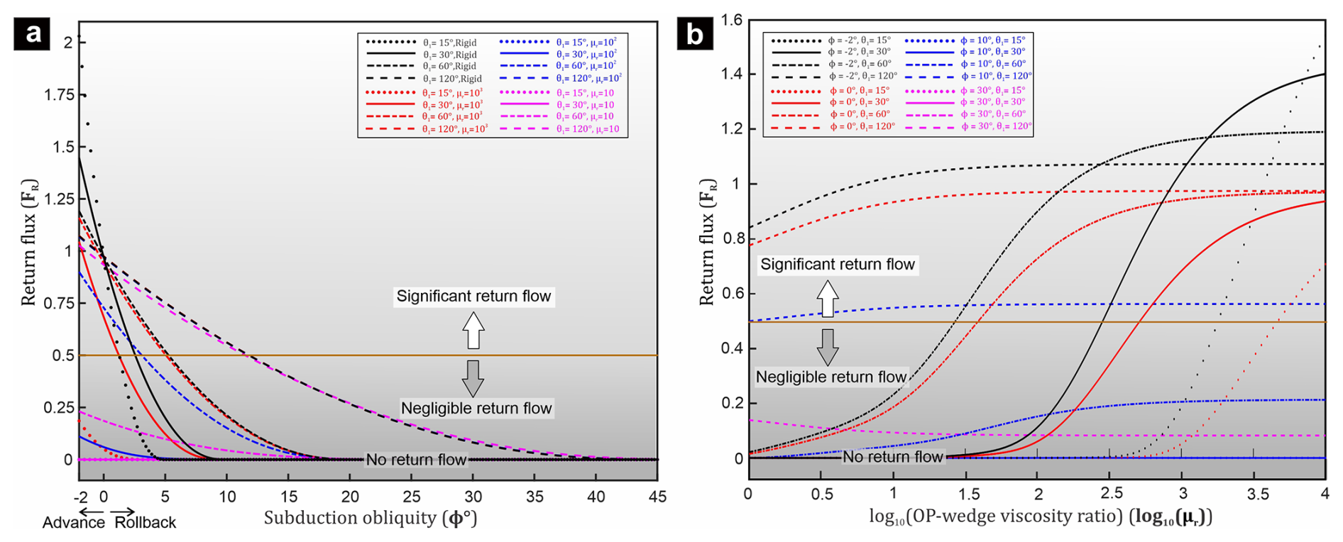
Figure 10Analytically determined plots of return flux (FR) as a function of (a) subduction obliquity (ϕ), and (b) viscosity ratio (μr), for varying taper angles (θ1) of the wedge. Note that for low to moderate taper angles (θ1≤30°), significant return flux (FR>0.5) occurs when μr is large (≥∼103), and there is no slab rollback (ϕ0° or negative).
5.2 Exhumation of high P metasediments by return flows: model vs. nature
Subduction zones generally host distinct types of high-pressure low-temperature (HP–LT) metamorphic rocks: metamorphosed oceanic sediments, oceanic crust (+ mantle), and continental crust, each of them records its own exhumation process (Agard et al., 2009, 2001; Burov et al., 2001; Gerya et al., 2002; Angiboust et al., 2012). The exhumation of oceanic sediments in accretionary wedges usually occurs as a syn-convergent steady process operating on tens of million years, whereas oceanic crustal fragments record episodic exhumation events corresponding to different stages of subduction (Husson et al., 2009; Yamato et al., 2007; Wang et al., 2019). They also show varying modes of occurrences in the subduction settings. High pressure metasediments occur as extensive, continuous metasedimentary outcrops with smooth, progressively increasing P-T conditions (Agard et al., 2001; Ernst, 1993; Vaughan-Hammon et al., 2022). On the other hand, exhumed oceanic crustal bodies form distinct slices of units, often associated with serpentinites, and exhibit contrasting P-T peaks, as reported from the Western Alps (Agard et al., 2009; Schwartz et al., 2001; Angiboust et al., 2012). Previous studies have used the corner flow mechanism to explain the exhumation of high-pressure metasedimentary rocks in terms of return flows in accretionary wedges (Allemand and Lardeaux, 1997; Gerya et al., 2002; Shreve and Cloos, 1986). The present theoretical analyses suggest that accretionary wedges can produce such return flows only in specific conditions determined by a number of parameters, such as subduction obliquity, OP-wedge viscosity ratio, and taper angle of the wedge, as shown in Fig. 10.
The relative volume of exhumed high-pressure metasedimentary rocks varies significantly in the accretionary wedges of convergent settings (Kerswell et al., 2023). Agard et al. (2009) have provided estimates recycled volume budgets of subducted sediments, ∼80 %–90 % in the Cascades, whereas 30 %–50 % in the Western Alps. However, the estimates yield remarkably low values, <1 % in the Chile and Franciscan complex. Although low preservation potential of blueschist facies rocks or differential erosional effects are possible factors for such variations, the flow kinematics in the accretionary wedge seems to be one of the most influential factor in determining the amounts of uplifted masses. Our theoretical analyses reveal that extensive return flows can occur in specific kinematic, rheological and geometrical conditions. For example, in the Cascades and the Western Alps, the ratio of returned to subducted material volumes at any instant within a steady state accretionary wedge (FR) has been estimated high (>0.5) (Agard et al., 2009). The present theoretical results suggest the following: (1) subduction with little or no slab rollback, (2) high relative strength of the overriding plate (), and (3) large wedge taper angles (θ1) as potential conditions favoring such high return flow kinematics. For small taper angles (°) and weak overriding plates (), the settings hardly return materials within the wedge, the quantity of which can be further reduced by slab rollback (Figs. 4b-i, 5b-i, 9a, c). For relatively weak overriding plates (OP), the return flows originating from deeper regions eventually deflect towards the overriding plate, resulting in exhumation of both the wedge and OP materials in the retroside regions (Butler et al., 2011), at extremely slow rates (<0.1U for a setting with μr=102, and θ1=30°) (Fig. 11a). However, such sluggish uplift processes do not support them to travel much in the upward direction. Extremely weak (μr<10) OP settings, however, produce flows closely similar to those formed in a single (i.e., μr=1) corner model with a large taper angle, enabling the crustal materials to uplift at considerable velocities and accumulate in the retroside of the wedge. Slab rollback at a relatively higher velocity (keeping the OP fixed) suppresses the return flows, instead it facilitates leaking of crustal materials through a narrow passage into the mantle (Figs. 3c-i, d-i, 4b-i, c-i, e-i, f-i). However, the same tectonic setting favours exhumation in other rocks, such as oceanic crustal units, low-density continental blocks and mantle rocks (Brun and Faccenna, 2008; Husson et al., 2009; Wang et al., 2019), as the slab rollback and associated upper plate extension create free spaces within the lower- or upper plate-side of the fore-arc, setting a dynamic condition for the exhumation of (U) HP rocks from mantle depths. On the other hand, our model results suggest that a period of slab advance during subduction can facilitate the extrusion process in the wedge, resulting in exhumation of deep-crustal materials (Figs. 3b-i, 5a-i, d-i, 8b).
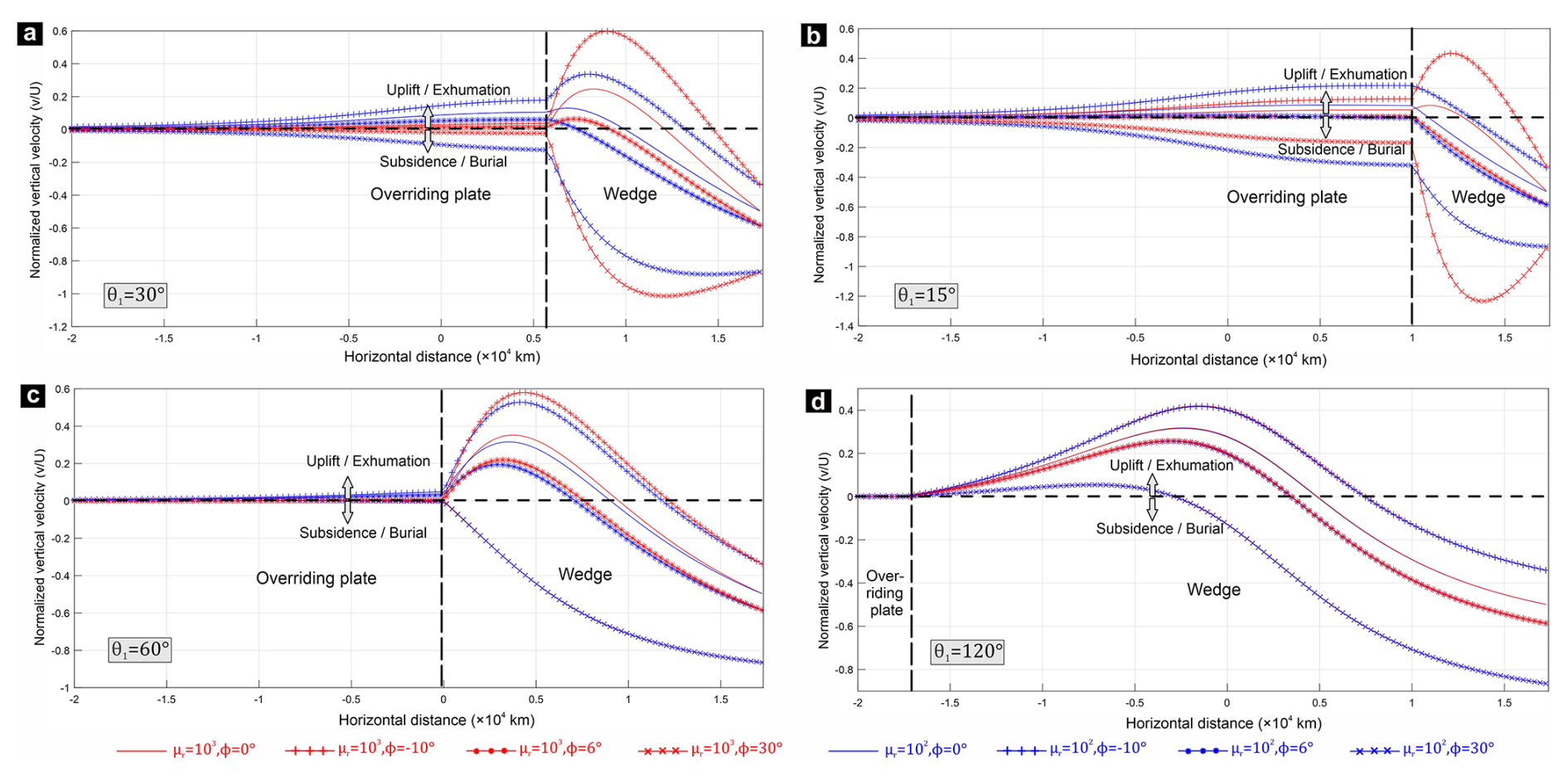
Figure 11Vertical-velocity profile (at y=10 km) across the wedge and the overriding plate in analytical models with different θ1 (a–d), μr, and ϕ. Positive and negative values of the vertical velocity indicate uplift/exhumation and subsidence/burial of wedge materials, respectively.
The calculated extrusion velocities of HP-LT rocks in accretionary belts vary on a wide range, from <1 mm yr−1 to >1 cm yr−1 (see Table 1b of Agard et al., 2009, and references therein), but they mostly lie in the order of mm yr−1. In contrast, previous CF model studies yield extrusion velocities much higher than 1 cm yr−1 (Allemand and Lardeaux, 1997; Cloos, 1982; Gerya et al., 2002), which perhaps occur due to the geometrical and kinematic boundary conditions chosen in the models. The present theoretical analysis, however, suggests that the return flows can be significantly slow due to specific mechanical and geometric conditions: low relative viscosities of the overriding plates () and small taper angles (°) (Fig. 11a, b). For θ1=30°, accretionary wedge models with μr=103 and 102 yield maximum vertical uplift velocities (vmax) about one-fourth and one-eighth of the wedge basal velocity (U), respectively (Fig. 11a). As the material particles track curvilinear paths, they would be extruded mostly at velocities less than vmax, and their time-averaged velocity would be less than vmax. Our theoretical estimates are consistent with those (1–5 mm yr−1) calculated from the Schistes Lustres complex in the Western Alps (–2 cm yr−1, Yamato et al., 2007) and other accretionary belts (Brandon et al., 1998; Glodny et al., 2005; Ring et al., 1999). The theoretical results further indicate that syn-subduction slab rollback (ϕ>0°), even small in magnitudes can again weaken the return flow kinematics, reducing the exhumation velocities to a large extent (<1 mm yr−1; Fig. 11a–d). Additionally, discrete slip along the wedge-subducting plate interface can also decrease the exhumation velocity (v), as v is directly proportional to the velocity (U) at the base of the wedge. Other mechanisms, such as gravitational spreading at shallow crustal level (Van Dinther et al., 2012), deformation localization, syn-subduction sediment accumulation can also contribute to a reduction in the exhumation velocity. Therefore, in contrast to the prevailing notion that the extremely slow exhumation rates result solely from erosion (Brandon et al., 1998; Platt, 1993) and other reasons discussed above, our model findings suggest that corner flow processes can also modulate the kinematics of extrusion of deep HP rocks to the surface at slow rates.
High-pressure rocks in many convergent belts record unusually high uplift rates. As an example, the Ampelos/Dilek nappe of the Cycladic blueschist unit in the eastern Aegean underwent extrusion at rates 3–3.5 cm yr−1 during incipient collision of the Anatolian microcontinent with Eurasia (Ring et al., 2007). Our model results suggest that mechanically strong overriding plates ( Pa s) and/or significant slab advance (ϕ<0°) kinematics form potential convergent settings for high-rate extrusion in wedges with moderate tapering angles (Figs. 8b, 11a, b). In addition, large crustal scale normal-sense shear zones (or faults) within the wedge or at the wedge-overriding plate contact can exhume high P rocks at fast rates (Bento dos Santos et al., 2021; Searle, 2015). Presence of buoyant crustal blocks and erosion can further facilitate the extrusion kinematics (England and Holland, 1979; Ernst et al., 1997; Godin et al., 2006). The present theoretical estimates also account for relatively higher extrusion rates (∼1 cm yr−1) in wider wedges with large taper angles (Fig. 11c, d).
5.3 Deformation patterns
Accretionary wedge deformations have generally been explained using the critical taper theory in the framework of Coulomb rheology (Dahlen, 1990; Dahlen et al., 1984; Buiter, 2012). However, this rheological consideration may not provide good approximations for wedges thicker than ∼15 km as thermally activated ductile deformation mechanisms become significant in controlling the rheology of the wedge materials at depths (Pavlis and Bruhn, 1983; Platt, 1986). The depth of brittle-ductile transition is strongly controlled by the prevalent thermal regime (Stewart et al., 2000). Below this depth, viscous flow regimes govern the deformation patterns across the wedge (Fig. 2a).
The model results presented in the preceding section indicate that the deformation styles in convergent settings strongly depend on a number of geometric and kinematic parameters: slab motion, overriding plate's relative viscosity (μr), and wedge taper angle. Three distinct modes of deformation can be recognized in the field diagram of Fig. 12, each with a characteristic vorticity pattern. The central part of the diagram defines a field of no shear reversal, i.e., the whole wedge is characterized by the same shear sense, as imposed by the SP. The central field is bounded by two lines, the locus of which varies with μr. To the left and right of this field, the shear sense reverses in the upper (i.e., near the OP) and lower (i.e., near the SP) regions of the wedge, respectively. The variation in the wedge kinematics is essentially a consequence of the interplay between the slab-driven Couette flow and the dynamic pressure-driven Poiseuille flow (see Sect. S2 for a detailed discussion). For moderate to high μr (), subduction, with or without slab advance (i.e., zero or negative ϕ), the wedge settings produce two synchronous domains of shear deformations with opposite shear senses: thrust shear in the lower part and normal shear in the upper part of the wedge (Figs. 4a-ii, b-ii, 5a-ii, b-ii) . The shear reversal is accompanied by a systematic variation of the strain fields, with sub-horizontal principal shortening axes close to the subducting plate, which reorient to become sub-vertical towards the overriding plate. Wider wedges, characterized by oppositely-dipping walls transforms the shear patterns into doubly-vergent thrust sense shears, separated by a zone of normal-sense shear in their axial regions (Deville, 2023; Luján et al., 2010) (Fig. 6c-ii). However, the shear reversibility disappears if μr is low () and the slab retreat (i.e., positive ϕ) becomes active. For a moderately tapering wedge, the later can give rise to thrust-sense shearing in the entire wedge (Figs. 3c-ii, 4c-ii, 5b-ii, e-ii), with the exceptions that high slab rollback velocities develop normal-sense (with subhorizontal extension) and thrust-sense shearing close to the subducting and the overriding plate, respectively (Figs. 3d-ii, 5c-ii, f-ii). Similar variations in the shear kinematics across the wedge are also evident from the deflection of marker lines after finite deformation in the experimental models (Fig. 12i–iv). The analogue models also suggest that after considerable deformation, the topographic slope generated at the upper surface of relatively low viscosity wedge sets in gravity-driven flow that leads to horizontal extension in the rear part of the wedge, as also reported from previous analogue experiments (Chattopadhyay and Mandal, 2002; Luján et al., 2010).
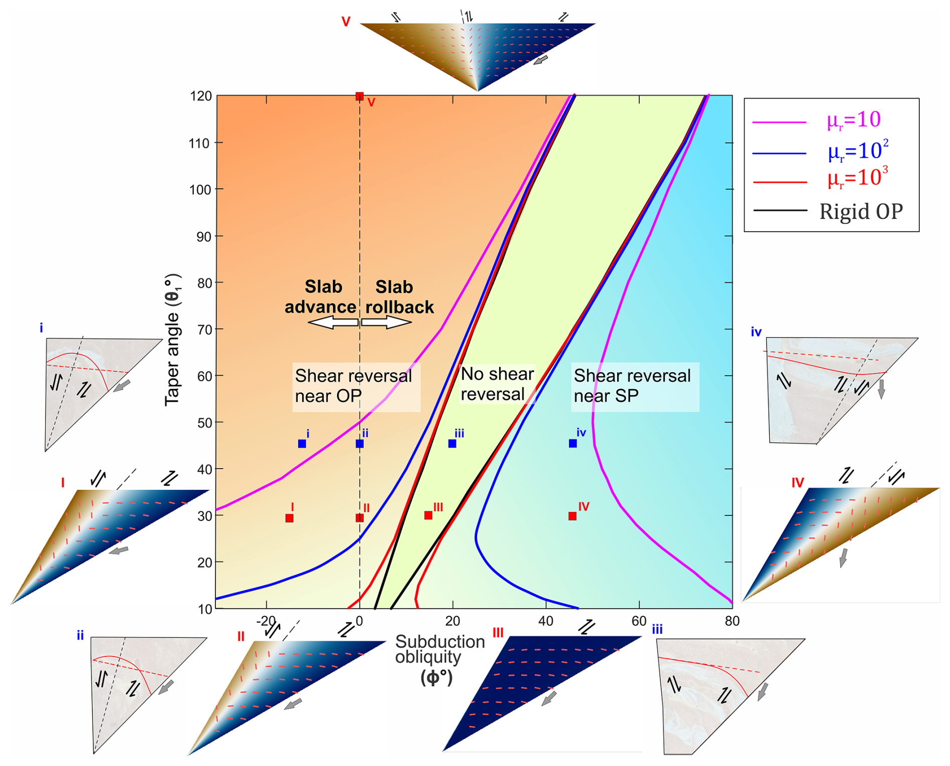
Figure 12Fields of “shear reversal” and “no shear reversal” across the wedges in a parametric space defined by subduction obliquity (ϕ), taper angle (θ1), and viscosity ratio (μr). To the left and right sides of the central “no shear reversal” field, shear sense reverses differently, as shown in the analytically determined vorticity regimes at various positions (I–V small red squares) of the field diagram for μr=103. Short red dashes in I–V mark the orientations of ISAmin. Red solid lines within the wedges (i–iv) indicate deflection of initial straight markers (red dashed lines) after 10 km of shearing in experimental models (μr=102) for varying subduction obliquities (see small blue squares).
The shear reversal phenomenon has been reported from extruded rocks in several subduction zones (e.g., Hellenides, Ducharme et al., 2022; Western Alps, Agard et al., 2001; Sambagawa Belt, Osozawa and Wakabayashi, 2015) and collisional belts (e.g., the Cycladic blueschist unit in the Eastern Aegean, Ring et al., 2007; Himalayan mountain belts, Beaumont et al., 2001; Grujic et al., 2002; Dutta and Mukherjee, 2021, 2019; the Porto–Viseu Metamorphic Belt in the Central-Iberian Zone, Bento dos Santos et al., 2021). Considering a steady state flow kinematics, crustal materials following their burial to greater depths are recycled back to the surface by return flows and experience shear deformations in both lower and upper domains of the wedge. Consequently, they can record thrust-sense shear structures in them, overprinted by normal-sense shear structures during exhumation, as observed in the Cycladic Blueschist Unit at Fabrika (Ring et al., 2020). Such corner-flow driven complex tectonics can produce deformational structures under sub-horizontal shortening in the burial phase, which are superposed by structures related to sub-vertical shortening. Multiple structural fabrics, and fluid-assisted deformations develop in the course of a progressive tectonic event, without any change in the external kinematic frame (Richter et al., 2007; Muñoz-Montecinos and Behr, 2023). The strain fields at the time of exhumation indicate sub-vertical crustal shortening and tectonic thinning (Feehan and Brandon, 1999; Ring and Brandon, 2008; Kryl et al., 2021), manifested in sub-horizontal foliations, which are superposed on earlier tectonic structures, such as folds and fabrics in several paleo-accretionary wedges e.g., San Juan-Cascade nappes, coastal accretionary belt of Chile (Richter et al., 2007; Muñoz-Montecinos et al., 2020). Crustal scale extensional (normal) shear zones that localize in the upper part of the wedge largely control the exhumation of high grade metamorphic rocks beneath low grade rocks in subduction and collisional settings (Searle, 2015). The extensional shearing in the deeper region gives way to normal faulting at the shallow crustal level in the hinterland as the return flows result in vertical crustal uplift in the rear of the wedge (Figs. 11, S3, S4). This uplift develops normal faulting to retain the stability (Platt, 1986). The normal faults further assist in the exhumation of high P materials, especially at shallow crustal depths (Platt, 1993; Ring et al., 1999).
In subduction zones, the subducting oceanic slabs can induce strong deformations in their overriding plates, often manifested in characteristic topographic developments (Buiter et al., 2001; Dasgupta and Mandal, 2018; Hampel and Pfiffner, 2006; Shijie Zhong and Gurnis, 1994). Previous studies suggest that the forces responsible for such OP deformations originate in several ways, viscous drag at the base of the overriding plate, suction effects between the subducting and the overriding plate, and shear generated at the slab interface (Chen et al., 2017; Schellart, 2024, and references therein) A detailed discussion of their independent role is beyond the scope of this study. However, our theoretical analysis suggests that the shear force generated by the subducting plate can induce large crustal deformations in the overriding plate only under specific conditions constrained by the overriding plate viscosity, and the subduction kinematics (slab advance vs. rollback). High μr () allows the overriding plates to accommodate little shear exerted by the wedge flows. Consequently, they undergo little deformations ( s−1) and hardly produce topographic uplifts. This condition rather facilitates the return flows in localizing high uplifts within the wedge rear. Moderate to low μr favours the overriding plate to transmit the wedge-induced shear and undergo deformations with considerable uplift rates (Figs. 9a, 11a, b). This condition thus results in a widely uplifted region in the forearc. Such fore-arc uplifts are more pronounced in wedges with large taper angles (which is equivalent to μr=1) (Fig. 11c, d). This interpretation explains the occurrence of broad forearc highs in many long-lived, large accretionary complexes, such as the Lesser Antilles, the Alaskan, the Makran, and the Cyprus-Anatolian margin (Pavlis and Bruhn, 1983). Several authors have presented similar interpretations for the tectonics of fore-arc highs, emphasizing the role of upward viscous flows in the lower crust (Fernández-Blanco et al., 2020; Pavlis and Bruhn, 1983). The uplift velocity of the fore-arc region increases when the slab advance accompanies subduction (Figs. 8b, 9b, 11). The slab rollback, in contrast, forces weaker overriding plate () to flow towards the wedge, resulting in fore-arc subsidence, as also observed in the physical experiments (Fig. 9c-i, ii). These results are in agreement with the previous experimental results where the subduction setup produced fore-arc subsidence and sub-horizontal extension during the trench retreat (Chen et al., 2017; Xue et al., 2022).
5.4 Can accretionary wedges generate significant tectonic overpressures?
Pressure estimates from geobarometry of exhumed metamorphic rocks are generally equated with the depth (h) of metamorphism and reconstruction of the tectonic history, assuming that the lithostatic pressure, p=ρgh, where ρ is the average rock density, and g is the gravitational acceleration. However, this condition applies essentially to a static fluid condition. A direction of studies accounts for the effects of dynamic pressure, calculated as the difference between the total pressure (or mean stress) and lithostatic pressure, i.e., excess pressure (Mancktelow, 1995; Petrini and Podladchikov, 2000). This can be hundreds of MPa or even several GPa higher (tectonic overpressure) or lower (tectonic underpressure) than the corresponding lithostatic pressure. Several numerical model studies claim the possibility of tectonic overpressure (TOP) in subduction-collisional zones (Li et al., 2010; Marques et al., 2018; Raimbourg and Kimura, 2008; Reuber et al., 2016). It has been shown theoretically that in the brittle regime, faulting in compression occurs under pressures of tens to hundreds of MPa, where the total pressure reaches up to twice the lithostatic pressure in dry rocks (Mancktelow, 2008; Petrini and Podladchikov, 2000). Mancktelow (1995), Moulas et al. (2021) analytically determined tectonic overpressure in downward tapering viscous subduction channels bounded by rigid and deformable wall(s), respectively. We use our analytical solution to evaluate the maximum dynamic pressure (Pdmax) in a wedge, which is found to be a function of several parameters: subduction velocity vector (U: both magnitude and direction), overriding plate velocity (Uop), the taper angle (θ1) and viscosity (μ1) of the wedge, and overriding plate-wedge viscosity ratio (μr). The following conditions: high μ1, μr, U, Uop and low ϕ (negative), θ1 values give rise to higher values of Pdmax (Fig. 13).
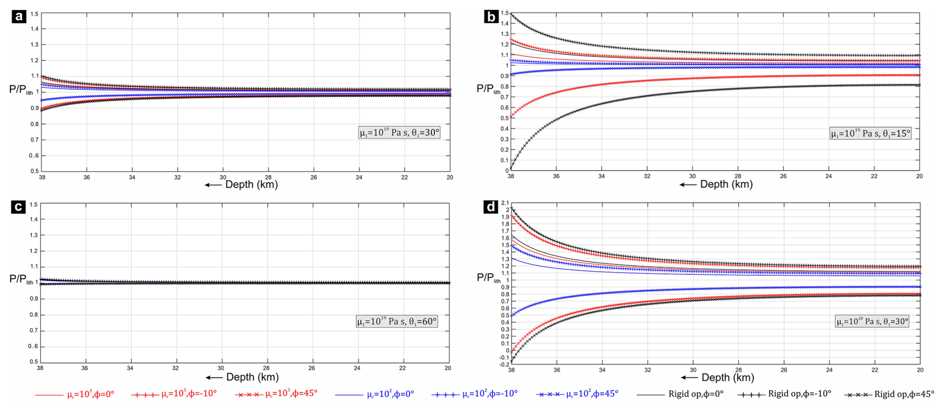
Figure 13Plot of the total pressure (P), normalized to the lithostatic pressure (Plith) along the acute bisectors of the wedges for varying μ1, θ1, μr, and ϕ. Plith is calculated assuming the overburden density as 2800 kg m−3.
The magnitude of dynamic pressure in the downward-tapering wedge increases towards the tip and theoretically becomes infinity at the wedge tip (S-point), a singularity point. Natural accretionary wedges, however, are likely to possess a finite width at its base instead of terminating at a single point, as some volumes of the incoming sediments leak through the bottom of the accretionary wedges and form the deeper subduction channel (Agard et al., 2009). Hence, we find it reasonable to not consider the anomalously high dynamic pressure at the bottom 2 km of our model wedge. This gradient in dynamic pressure drives the exhumation of deep-crustal HP rocks (Fig. 1b). The dynamic pressure scales linearly with the viscosity (μ1) of the wedge materials. The choice of viscosity values is a critically important issue in the dynamic pressure calculations. Field data, compiled from a range of exhumed subduction complexes and experimental rock deformations suggest μ1 in the ranges of ∼1018 to 1020 Pa s at the subduction interfaces (Abila et al., 2025). For our calculations, we thus consider μ1=1019 Pa s for metasedimentary rocks in the wedge (Behr and Becker, 2018). Our analytical results show that for a moderate subduction velocity of 3 cm yr−1 and a moderate taper angle of 30°, maximum TOP is less than 8 % of the lithostatic pressure in a wedge with μ1=1019 Pa s (Fig. S1). The magnitude of Pdmax reduces further to <4 % with a decrease in the overriding plate viscosity, μ2≤1021 Pa s (Fig. 13a, b, c). The magnitude of dynamic pressure can be of one order higher in wedges with higher viscosity (μ1≥1020 Pa s) (Fig. 13d). Hence, some high-pressure rocks record extremely fast exhumation rates, as calculated from lithostatic pressure approximations might reflect the influence of TOP at relatively shallow depths ( km) (Marques et al., 2018). Presence of high viscosity units can also lead to higher TOP in less competent materials with lower deviatoric stress, due to force-balance requirements (Schmalholz et al., 2014; Schmalholz and Podladchikov, 2013). TOP also increases for narrower wedges with lower taper angles (Fig. 13b). Extremely small taper angles, however, does not produce significant dynamic pressure, unless the overriding plate is relatively very strong (viscosity Pa s). A weak overriding plate cannot sustain a narrow wedge, and with progressive time, the wedge develops a rearward bulge close to the corner (Fig. 9a-iii). This causes further drop in dynamic pressure at the wedge base. Tectonic overpressure becomes extremely low (<2 %) in wider wedges (Fig. 13c). In addition, our theoretical results indicate that the process of slab advance can elevate the TOP in the subduction zone (Figs. 13, S2). On the contrary, slab rollback creates a condition of tectonic underpressure (TUP) within the wedge, the magnitude of which increases towards depth (Fig. 13).
To summarize, several previous studies have emphasized the importance of tectonic overpressure in exhumed HP units. The present study suggests that for accretionary wedges comprising of low viscosity sediments, the nonlithostatic pressure component is small, generally in the order of tens of MPa (Reuber et al., 2016; Yamato et al., 2007). Significant tectonic overpressure can develop if any of these following conditions are satisfied: (1) wedges consist of materials of high viscosity, (2) the wedge is narrow with a strong hanging wall, and (3) the subduction involves slab advance.
The theoretical modelling approach used in this study is simplified in the fact that it assumes an already existing homogeneous viscous wedge above the subducting plate, and also excludes the complex processes (e.g., accretion, sedimentation, erosion) in the accretionary wedges (Angiboust et al., 2022; Clift and Vannucchi, 2004; Simpson, 2010). Moreover, the models consider the whole accretionary wedge and the overriding plate crust as Newtonian viscous materials of constant viscosities and equal densities, and thereby do not account for the effects of non-linear, or depth-dependent rheology of the crust (Ranalli, 1995). In natural wedges, presence of crustal heterogeneities, or discrete shear zones can alter the velocity field predicted from our analytical models with a continuum approximation (Borderie et al., 2018; Grujic, 2006; Jaquet et al., 2018). However, considering that small-scale (with respect to the bulk wedge dimension) perturbations, such as shear zones, are averaged out, we analyze the first-order velocity field using the continuum approximation. The effect of buoyancy forces in orogenic wedges, arising from density contrast between the wedge materials and the surrounding (Burov et al., 2014; Candioti et al., 2021) is also neglected in the models. Another limitation is the assumption of a rigid upper mantle, represented by the rigid model base in experiments, which do not allow any wedge material to flow across the Moho. In natural subduction zones, however, part of the incoming sediments may leak through the accretionary wedge bottom in the form of a deep subduction channel (Clift and Vannucchi, 2004; Guillot et al., 2009). In spite of these limitations, the present theoretical and analogue models provide significant insights into the effects of the various parameters (geometric, kinematic and rheological) on the first order kinematics of a mature, steady-state wedge (Yamato et al., 2007). Our analytical model gives us an instantaneous velocity field under a given wedge geometry. For a deformable overriding plate, or slab-oblique kinematics, the wedge, however, undergoes geometrical modifications with progressive subducting slab movement. Particularly, progressive slab rollback replaces the S-point in the tapered geometry by a separation of finite width on the base. The analytical results are applicable if the separation remains small in the course of slab migration. Analogue models, run for significant finite movements, however, allow us to investigate the temporal evolution of wedge kinematics. Experimental results suggest that the velocity pattern predicted from analytical solutions remain qualitatively unchanged even after considerable finite deformation, until gravity-driven flows begin to capture the wedge kinematics at shallow depths.
A generalized analytical solution of the corner flow theory has been derived to study the kinematics of crustal flows in viscous accretionary wedges, with a special emphasis on the criticality of the conditions required for return flows and thereby exhumation of deep-crustal rocks in convergent tectonic boundaries. The analytical solution, supported by scaled physical laboratory model experiments, suggest that the subduction obliquity (ϕ), overriding plate-wedge viscosity ratio (μr) and the taper angle (θ1) of the wedge are principal factors in determining the velocity and strain fields within the accretionary wedge. The principal findings of this study are concluded in the following: 1) Accretionary wedges can produce focused return flows specifically in settings with , °, and subduction with little or no slab rollback. The slab rollback (ϕ>0°) process drastically weakens the return fluxes in the wedges. (2) Return flow velocities in the deeper regions of wedges can range from <1 mm yr−1 to a few cm yr−1. Slab advance (ϕ<0°) during the subduction promotes the vertical flow velocities, attaining maximum values comparable to the subduction velocity, provided the overriding plate is strong ( Pa s) and wedge taper angle is not low (°). (3) The shear sense may reverse across the wedge under a critical combination of the aforesaid parameters. (4) Weak overriding plates () accommodate significant amounts of global deformations, resulting in vertical uplifts and subsidence for slab-parallel subduction or advance, and rollback, respectively. (5) Accretionary wedges comprising low-viscosity (∼1019 Pa s) sediments are unlikely to develop large tectonic overpressures (or underpressures).
We show the detailed expressions of the eight equations used for deriving the eight constants Ai, Bi, Ci, Di (i=1, 2). These eight equations are derived from the eight boundary conditions. The velocity conditions at the wedge base (Eq. 13) follow:
At the Moho in the overriding plate (OP), the velocity boundary conditions (Eq. 14) are expressed as:
Using the continuity condition for the two velocity components across the wedge–OP interface (Eq. 15), we obtain the following relations:
Lastly, the continuity of normal and shear stress components across the wedge–OP interface (Eq. 19) leads to:
By solving the eight equations above, we find the expressions of the eight constants:
Substituting the expressions of these eight constants in Eqs. (12) and (11), the two stream functions (ψ1 and ψ2) are calculated. These two stream functions (Eq. 11) are then utilized to find the velocity field in the wedge as well as the overriding plate.
The relevant data used to support the findings of this study are available in the article and in the Supplement. MATLAB scripts are provided in the repository (https://doi.org/10.6084/m9.figshare.29331581, Patsa and Mandal, 2025). These sample files can be used for the calculation and visualization of the analytical results and graphs presented in this work.
The supplement related to this article is available online at https://doi.org/10.5194/se-17-573-2026-supplement.
AP conducted the theoretical analysis, performed the laboratory experiments, and prepared the original draft of the manuscript. NM conceptualized the research idea, supervised the methodologies. Both the authors edited and revised the manuscript and approved the final version.
The contact author has declared that neither of the authors has any competing interests.
Publisher's note: Copernicus Publications remains neutral with regard to jurisdictional claims made in the text, published maps, institutional affiliations, or any other geographical representation in this paper. The authors bear the ultimate responsibility for providing appropriate place names. Views expressed in the text are those of the authors and do not necessarily reflect the views of the publisher.
We sincerely thank two anonymous reviewers for critically reviewing the earlier versions of this manuscript, providing many valuable suggestions for improvement of this study. We also thank Associate Editor Taras Gerya, and Executive Editor Florian Fusseis for their insightful editorial handling. This work has been supported by the DST-SERB through J. C. Bose fellowship (JBR/2022/000003) to NM. AP gratefully acknowledges CSIR, India for awarding him a Senior Research Fellowship grant (09/096(1029)/2020-EMR-I).
This research has been supported by the Science and Engineering Research Board (grant no. JBR/2022/000003) and Council of Scientific and Industrial Research (Fellowship grant no. 09/096(1029)/2020-EMR-I).
This paper was edited by Taras Gerya and reviewed by two anonymous referees.
Abers, G. A.: Seismic low-velocity layer at the top of subducting slabs: observations, predictions, and systematics, Phys. Earth Planet. In., 149, 7–29, https://doi.org/10.1016/j.pepi.2004.10.002, 2005. a
Abers, G. A., Van Keken, P. E., and Hacker, B. R.: The cold and relatively dry nature of mantle forearcs in subduction zones, Nat. Geosci., 10, 333–337, https://doi.org/10.1038/ngeo2922, 2017. a
Abila, A. L., Behr, W. M., and Ruh, J.: Strength of viscous subduction interfaces: A global compilation, Geology, 53, 105–108, https://doi.org/10.1130/G52518.1, 2025. a
Agard, P., Jolivet, L., and Goffé, B.: Tectonometamorphic evolution of the Schistes Lustres Complex; implications for the exhumation of HP and UHP rocks in the Western Alps, Bulletin de la Société Géologique de France, 172, 617–636, https://doi.org/10.2113/172.5.617, 2001. a, b, c, d, e, f
Agard, P., Monié, P., Jolivet, L., and Goffé, B.: Exhumation of the Schistes Lustrés complex: in situ laser probe 40Ar/39Ar constraints and implications for the Western Alps, J. Metamorph. Geol., 20, 599–618, https://doi.org/10.1046/J.1525-1314.2002.00391.X, 2002. a
Agard, P., Yamato, P., Jolivet, L., and Burov, E.: Exhumation of oceanic blueschists and eclogites in subduction zones: Timing and mechanisms, Earth-Sci. Rev., 92, 53–79, https://doi.org/10.1016/J.EARSCIREV.2008.11.002, 2009. a, b, c, d, e, f, g, h, i, j, k
Agard, P., Plunder, A., Angiboust, S., Bonnet, G., and Ruh, J.: The subduction plate interface: rock record and mechanical coupling (from long to short timescales), Lithos, 320-321, 537–566, https://doi.org/10.1016/J.LITHOS.2018.09.029, 2018. a
Allemand, P. and Lardeaux, J. M.: Strain partitioning and metamorphism in a deformable orogenic wedge: Application to the Alpine belt, Tectonophysics, 280, 157–169, https://doi.org/10.1016/S0040-1951(97)00136-4, 1997. a, b, c, d, e, f
Anderson, D. M. and Davis, S. H.: Two-fluid viscous flow in a corner, J. Fluid Mech., 257, 1–31, https://doi.org/10.1017/S0022112093002976, 1993. a, b
Angiboust, S., Wolf, S., Burov, E., Agard, P., and Yamato, P.: Effect of fluid circulation on subduction interface tectonic processes: Insights from thermo-mechanical numerical modelling, Earth Planet. Sc. Lett., 357, 238–248, https://doi.org/10.1016/j.epsl.2012.09.012, 2012. a, b
Angiboust, S., Menant, A., Gerya, T., and Oncken, O.: The rise and demise of deep accretionary wedges: A long-term field and numerical modeling perspective, Geosphere, 18, 69–103, https://doi.org/10.1130/GES02392.1, 2022. a, b, c
Batchelor, G. K.: An Introduction to Fluid Dynamics, Cambridge University Press, ISBN 9780511800955, 1967. a
Beaumont, C., Jamieson, R., Butler, J., and Warren, C.: Crustal structure: A key constraint on the mechanism of ultra-high-pressure rock exhumation, Earth Planet. Sc. Lett., 287, 116–129, https://doi.org/10.1016/j.epsl.2009.08.001, 2009. a
Beaumont, C., Ellis, S., and Pfiffner, A.: Dynamics of sediment subduction-accretion at convergent margins: Short-term modes, long-term deformation, and tectonic implications, J. Geophys. Res.-Sol. Ea., 104, 17573–17601, https://doi.org/10.1029/1999JB900136, 1999. a
Beaumont, C., Jamieson, R. A., Nguyen, M. H., and Lee, B.: Himalayan tectonics explained by extrusion of a low-viscosity crustal channel coupled to focused surface denudation, Nature, 414, 738–742, https://doi.org/10.1038/414738A, 2001. a
Behr, W. M. and Becker, T. W.: Sediment control on subduction plate speeds, Earth Planet. Sc. Lett., 502, 166–173, https://doi.org/10.1016/J.EPSL.2018.08.057, 2018. a, b, c
Behr, W. M., Holt, A. F., Becker, T. W., and Faccenna, C.: The effects of plate interface rheology on subduction kinematics and dynamics, Geophys. J. Int., 230, 796–812, https://doi.org/10.1093/GJI/GGAC075, 2022. a
Bento dos Santos, T., Rodrigues, J. F., Castro, P., Cotrim, B., Pereira, I., Ferreira, J. A., Meireles, C., Ferreira, N., Ferreira, P., Ribeiro, A., and Guimarães, F.: Exhumation of an anatectic complex by channel flow and extrusion tectonics: structural and metamorphic evidence from the Porto–Viseu Metamorphic Belt, Central-Iberian Zone, Int. J. Earth Sci., 110, 2179–2201, https://doi.org/10.1007/s00531-021-02067-z, 2021. a, b
Bezada, M. J., Humphreys, E. D., Toomey, D. R., Harnafi, M., Dávila, J. M., and Gallart, J.: Evidence for slab rollback in westernmost Mediterranean from improved upper mantle imaging, Earth Planet. Sc. Lett., 368, 51–60, https://doi.org/10.1016/J.EPSL.2013.02.024, 2013. a
Borderie, S., Graveleau, F., Witt, C., and Vendeville, B. C.: Impact of an interbedded viscous décollement on the structural and kinematic coupling in fold-and-thrust belts: Insights from analogue modeling, Tectonophysics, 722, 118–137, https://doi.org/10.1016/J.TECTO.2017.10.019, 2018. a
Brandon, M. T., Roden-Tice, M. K., Garver, J. I., Brandon, M. T., Roden-Tice, M. K., and Garver, J. I.: Late Cenozoic exhumation of the Cascadia accretionary wedge in the Olympic Mountains, northwest Washington State, GSAB, 110, 985–1009, https://doi.org/10.1130/0016-7606(1998)110<0985:LCEOTC>2.3.CO;2, 1998. a, b, c
Brun, J. P. and Faccenna, C.: Exhumation of high-pressure rocks driven by slab rollback, Earth Planet. Sc. Lett., 272, 1–7, https://doi.org/10.1016/J.EPSL.2008.02.038, 2008. a
Buiter, S. J.: A review of brittle compressional wedge models, Tectonophysics, 530, 1–17, https://doi.org/10.1016/j.tecto.2011.12.018, 2012. a
Buiter, S. J., Govers, R., and Wortel, M. J.: A modelling study of vertical surface displacements at convergent plate margins, Geophys. J. Int., 147, 415–427, https://doi.org/10.1046/j.1365-246X.2001.00545.x, 2001. a
Burov, E. and Yamato, P.: Continental plate collision, P–T–t–z conditions and unstable vs. stable plate dynamics: Insights from thermo-mechanical modelling, Lithos, 103, 178–204, https://doi.org/10.1016/J.LITHOS.2007.09.014, 2008. a
Burov, E., Jolivet, L., Le Pourhiet, L., and Poliakov, A.: A thermomechanical model of exhumation of high pressure (HP) and ultra-high pressure (UHP) metamorphic rocks in Alpine-type collision belts, Tectonophysics, 342, 113–136, https://doi.org/10.1016/S0040-1951(01)00158-5, 2001. a, b
Burov, E., Francois, T., Yamato, P., and Wolf, S.: Mechanisms of continental subduction and exhumation of HP and UHP rocks, Gondwana Res., 25, 464–493, https://doi.org/10.1016/j.gr.2012.09.010, 2014. a
Butler, J. P., Beaumont, C., and Jamieson, R. A.: Crustal emplacement of exhuming (ultra)high-pressure rocks: Will that be pro- or retro-side?, Geology, 39, 635–638, https://doi.org/10.1130/G32166.1, 2011. a
Candioti, L. G., Duretz, T., Moulas, E., and Schmalholz, S. M.: Buoyancy versus shear forces in building orogenic wedges, Solid Earth, 12, 1749–1775, https://doi.org/10.5194/se-12-1749-2021, 2021. a, b, c
Cawood, P. A., Kröner, A., Collins, W. J., Kusky, T. M., Mooney, W. D., and Windley, B. F.: Accretionary orogens through Earth history, Geol. Soc. S. P., 318, 1–36, https://doi.org/10.1144/SP318.1, 2009. a, b
Cerpa, N. G. and Arcay, D.: Overriding Plate Velocity Control on Surface Topography in 2-D Models of Subduction Zones, Geochem. Geophy. Geosy., 21, e2019GC008900, https://doi.org/10.1029/2019GC008900, 2020. a
Chattopadhyay, A. and Mandal, N.: Progressive changes in strain patterns and fold styles in a deforming ductile orogenic wedge: an experimental study, J. Geodyn., 33, 353–376, https://doi.org/10.1016/S0264-3707(01)00079-5, 2002. a
Chemenda, A., Lallemand, S., and Bokun, A.: Strain partitioning and interplate friction in oblique subduction zones: Constraints provided by experimental modeling, J. Geophys. Res.-Sol. Ea., 105, 5567 – 5581, https://doi.org/10.1029/1999jb900332, 2000. a
Chemenda, A. I., Mattauer, M., Malavieille, J., and Bokun, A. N.: A mechanism for syn-collisional rock exhumation and associated normal faulting: Results from physical modelling, Earth Planet. Sc. Lett., 132, 225–232, https://doi.org/10.1016/0012-821X(95)00042-B, 1995. a
Chen, Z., Schellart, W. P., Duarte, J. C., and Strak, V.: Topography of the Overriding Plate During Progressive Subduction: A Dynamic Model to Explain Forearc Subsidence, Geophys. Res. Lett., 44, 9632–9643, https://doi.org/10.1002/2017GL074672, 2017. a, b
Clift, P. and Vannucchi, P.: Controls on tectonic accretion versus erosion in subduction zones: Implications for the origin and recycling of the continental crust, Rev. Geophys., 42, https://doi.org/10.1029/2003RG000127, 2004. a, b, c
Cloos, M.: Flow melanges: Numerical modeling and geologic constraints on their origin in the Franciscan subduction complex, California, GSA Bulletin | GeoScienceWorld, 93, 330–345, https://doi.org/10.1130/0016-7606(1982)93<330:FMNMAG>2.0.CO;2, 1982. a, b, c, d, e, f, g, h, i, j
Cloos, M. and Shreve, R. L.: Subduction-channel model of prism accretion, melange formation, sediment subduction, and subduction erosion at convergent plate margins: 2. Implications and discussion, Pure Appl. Geophys., 128, 501–545, https://doi.org/10.1007/BF00874549, 1988. a, b, c
Dahlen, F. A.: Critical taper model of fold-and-thrust belts and accretionary wedges, Annu. Rev. Earth Planet. Sci., 18, 55–99, https://doi.org/10.1146/ANNUREV.EA.18.050190.000415, 1990. a, b
Dahlen, F. A., Suppe, J., and Davis, D.: Mechanics of fold-and-thrust belts and accretionary wedges: Cohesive Coulomb Theory, J. Geophys. Res.-Sol. Ea., 89, 10087–10101, https://doi.org/10.1029/JB089IB12P10087, 1984. a, b
Dasgupta, R. and Mandal, N.: Surface topography of the overriding plates in bi-vergent subduction systems: A mechanical model, Tectonophysics, 746, 280–295, https://doi.org/10.1016/J.TECTO.2017.08.008, 2018. a
Deville, E.: Dynamics of Brittle-Viscous Accretionary Wedges as Revealed by Geophysical and Drilling Data and Analog Modeling of the Barbados Prism, Tectonics, 42, e2023TC007851, https://doi.org/10.1029/2023TC007851, 2023. a
Di Giuseppe, E., Faccenna, C., Funiciello, F., van Hunen, J., and Giardini, D.: On the relation between trench migration, seafloor age, and the strength of the subducting lithosphere, Lithosphere, 1, 121–128, https://doi.org/10.1130/L26.1, 2009. a
Doglioni, C., Carminati, E., Cuffaro, M., and Scrocca, D.: Subduction kinematics and dynamic constraints, Earth-Sci. Rev., 83, 125–175, https://doi.org/10.1016/j.earscirev.2007.04.001, 2007. a
Ducharme, T. A., Schneider, D. A., Grasemann, B., and Klonowska, I.: Stretched Thin: Oligocene Extrusion and Ductile Thinning of the Basal Unit Along the Evia Shear Zone, NW Cyclades, Greece, Tectonics, 41, e2022TC007561, https://doi.org/10.1029/2022TC007561, 2022. a
Dutta, D. and Mukherjee, S.: Opposite shear senses: Geneses, global occurrences, numerical simulations and a case study from the Indian western Himalaya, J. Struct. Geol., 126, 357–392, https://doi.org/10.1016/j.jsg.2019.05.008, 2019. a
Dutta, D. and Mukherjee, S.: Extrusion kinematics of UHP terrane in a collisional orogen: EBSD and microstructure-based approach from the Tso Morari Crystallines (Ladakh Himalaya), Tectonophysics, 800, 228641, https://doi.org/10.1016/j.tecto.2020.228641, 2021. a
Emerman, S. H. and Turcotte, D. L.: A fluid model for the shape of accretionary wedges, Earth Planet. Sc. Lett., 63, 379–384, https://doi.org/10.1016/0012-821X(83)90111-5, 1983. a
England, P. C. and Holland, T. J.: Archimedes and the Tauern eclogites: the role of buoyancy in the preservation of exotic eclogite blocks, Earth Planet. Sc. Lett., 44, 287–294, https://doi.org/10.1016/0012-821X(79)90177-8, 1979. a
Ernst, W.: Metamorphism of Franciscan tectonostratigraphic assemblage, Pacheco Pass area, east-central Diablo Range, California coast ranges, Geol. Soc. Am. B., 105, 618–636, 1993. a
Ernst, W. G.: Tectonic history of subduction zones inferred from retrograde blueschist P-T paths, Geology, 16, 1081, https://doi.org/10.1130/0091-7613(1988)016<1081:THOSZI>2.3.CO;2, 1988. a
Ernst, W. G., Maruyama, S., and Wallis, S.: Buoyancy-driven, rapid exhumation of ultrahigh-pressure metamorphosed continental crust, Proceedings of the National Academy of Sciences of the United States of America, 94, 9532–9537, https://doi.org/10.1073/PNAS.94.18.9532, 1997. a, b, c
Federico, L., Capponi, G., Crispini, L., Scambelluri, M., and Villa, I. M.: dating of high-pressure rocks from the Ligurian Alps: Evidence for a continuous subduction–exhumation cycle, Earth Planet. Sc. Lett., 240, 668–680, https://doi.org/10.1016/J.EPSL.2005.09.062, 2005. a
Feehan, J. G. and Brandon, M. T.: Contribution of ductile flow to exhumation of low-temperature, high-pressure metamorphic rocks: San Juan-Cascade nappes, NW Washington State, J. Geophys. Res.-Sol. Ea., 104, 10883–10902, https://doi.org/10.1029/1998JB900054, 1999. a
Fernández-Blanco, D., Mannu, U., Bertotti, G., and Willett, S. D.: Forearc high uplift by lower crustal flow during growth of the Cyprus-Anatolian margin, Earth Planet. Sc. Lett., 544, 116314, https://doi.org/10.1016/J.EPSL.2020.116314, 2020. a, b
Gerya, T.: Tectonic overpressure and underpressure in lithospheric tectonics and metamorphism, J. Metamorph. Geol., 33, 785–800, https://doi.org/10.1111/JMG.12144, 2015. a
Gerya, T. V., Stöckhert, B., and Perchuk, A. L.: Exhumation of high-pressure metamorphic rocks in a subduction channel: A numerical simulation, Tectonics, 21, 6–1, https://doi.org/10.1029/2002TC001406, 2002. a, b, c, d, e
Glodny, J., Lohrmann, J., Echtler, H., Gräfe, K., Seifert, W., Collao, S., and Figueroa, O.: Internal dynamics of a paleoaccretionary wedge: insights from combined isotope tectonochronology and sandbox modelling of the South-Central Chilean forearc, Earth Planet. Sc. Lett., 231, 23–39, https://doi.org/10.1016/J.EPSL.2004.12.014, 2005. a, b
Godin, L., Grujic, D., Law, R. D., and Searle, M. P.: Channel flow, ductile extrusion and exhumation in continental collision zones: An introduction, Geol. Soc. S. P., 268, 1–23, https://doi.org/10.1144/GSL.SP.2006.268.01.01, 2006. a
Grujic, D.: Channel flow and continental collision tectonics: An overview, Geol. Soc. S. P., 268, 25–37, https://doi.org/10.1144/GSL.SP.2006.268.01.02, 2006. a, b
Grujic, D., Hollister, L. S., and Parrish, R. R.: Himalayan metamorphic sequence as an orogenic channel: insight from Bhutan, Earth Planet. Sc. Lett., 198, 177–191, https://doi.org/10.1016/S0012-821X(02)00482-X, 2002. a
Guillaume, B., Martinod, J., and Espurt, N.: Variations of slab dip and overriding plate tectonics during subduction: Insights from analogue modelling, Tectonophysics, 463, 167–174, https://doi.org/10.1016/J.TECTO.2008.09.043, 2009. a
Guillot, S., Hattori, K., Agard, P., Schwartz, S., and Vidal, O.: Exhumation processes in oceanic and continental subduction contexts: a review, Subduction zone geodynamics, Springer, 175–205, https://doi.org/10.1007/978-3-540-87974-9_10, 2009. a, b
Hampel, A. and Pfiffner, A.: Relative importance of trenchward upper plate motion and friction along the plate interface for the topographic evolution of subduction-related mountain belts, Geol. Soc. S. P., 253, 105–115, https://doi.org/10.1144/GSL.SP.2006.253.01.05, 2006. a
Hebert, L. B., Antoshechkina, P., Asimow, P., and Gurnis, M.: Emergence of a low-viscosity channel in subduction zones through the coupling of mantle flow and thermodynamics, Earth Planet. Sc. Lett., 278, 243–256, https://doi.org/10.1016/j.epsl.2008.12.013, 2009. a
Hu, J. and Gurnis, M.: Subduction duration and slab dip, Geochem. Geophy. Geosy., 21, e2019GC008862, https://doi.org/10.1029/2019GC008862, 2020. a
Hu, J., Liu, L., and Gurnis, M.: Southward expanding plate coupling due to variation in sediment subduction as a cause of Andean growth, Nat. Commun., 12, 1–9, https://doi.org/10.1038/s41467-021-27518-8, 2021. a
Husson, L., Brun, J. P., Yamato, P., and Faccenna, C.: Episodic slab rollback fosters exhumation of HP-UHP rocks, Geophys. J. Int., 179, 1292–1300, https://doi.org/10.1111/j.1365-246X.2009.04372.x, 2009. a, b
Iwamori, H.: Viscous flow and deformation of regional metamorphic belts at convergent plate boundaries, J. Geophys. Res.-Sol. Ea., 108, https://doi.org/10.1029/2002JB001808, 2003. a
Jaquet, Y., Duretz, T., Grujic, D., Masson, H., and Schmalholz, S. M.: Formation of orogenic wedges and crustal shear zones by thermal softening, associated topographic evolution and application to natural orogens, Tectonophysics, 746, 512–529, https://doi.org/10.1016/J.TECTO.2017.07.021, 2018. a
Jarrard, R. D.: Relations among subduction parameters, Rev. Geophys., 24, 217–284, https://doi.org/10.1029/RG024I002P00217, 1986. a
Jolivet, L., Faccenna, C., Goffe, B., Burov, E., and Agard, P.: Subduction tectonics and exhumation of high-pressure metamorphic rocks in the Mediterranean orogens, Am. J. Sci., 303, 353–409, https://doi.org/10.2475/ajs.303.5.353, 2003. a
Kerswell, B. C., Kohn, M. J., and Gerya, T. V.: Computing rates and distributions of rock recovery in subduction zones, Geochem. Geophy. Geosy., 24, e2022GC010834, https://doi.org/10.1029/2022GC010834, 2023. a, b
Kryl, J., Jeřábek, P., and Lexa, O.: From subduction channel to orogenic wedge: Exhumation recorded by orthogneiss microstructures in Erzgebirge, Bohemian Massif, Tectonophysics, 820, 229096, https://doi.org/10.1016/j.tecto.2021.229096, 2021. a
Lallemand, S., Heuret, A., and Boutelier, D.: On the relationships between slab dip, back-arc stress, upper plate absolute motion, and crustal nature in subduction zones, Geochem. Geophy. Geosy., 6, https://doi.org/10.1029/2005GC000917, 2005. a
Lee, C. and Kim, Y. H.: Understanding subduction infancy to mature subduction in Southwest Japan via the self-consistent formation of a weak slab interface, Sci. Rep., 13, 1–14, https://doi.org/10.1038/s41598-023-48746-6, 2023. a
Li, Z. H., Gerya, T. V., and Burg, J. P.: Influence of tectonic overpressure on P–T paths of HP–UHP rocks in continental collision zones: thermomechanical modelling, J. Metamorph. Geol., 28, 227–247, https://doi.org/10.1111/J.1525-1314.2009.00864.X, 2010. a
Luján, M., Rossetti, F., Storti, F., Ranalli, G., and Socquet, A.: Flow trajectories in analogue viscous orogenic wedges: Insights on natural orogens, Tectonophysics, 484, 119–126, https://doi.org/10.1016/J.TECTO.2009.09.009, 2010. a, b, c
Maiti, G., Mandal, N., and Misra, S.: Insights into the dynamics of an orogenic wedge from lubrication theory: Implications for the Himalayan tectonics, Tectonophysics, 776, 228335, https://doi.org/10.1016/j.tecto.2020.228335, 2020. a
Mancktelow, N. S.: Nonlithostatic pressure during sediment subduction and the development and exhumation of high pressure metamorphic rocks, J. Geophys. Res.-Sol. Ea., 100, 571–583, https://doi.org/10.1029/94JB02158, 1995. a, b, c, d
Mancktelow, N. S.: Tectonic pressure: Theoretical concepts and modelled examples, Lithos, 103, 149–177, https://doi.org/10.1016/j.lithos.2007.09.013, 2008. a
Mandal, N., Samanta, S. K., and Chakraborty, C.: Flow and strain patterns at the terminations of tapered shear zones, J. Struct. Geol., 24, 297–309, https://doi.org/10.1016/S0191-8141(01)00065-7, 2002. a
Mannu, U., Ueda, K., Willett, S. D., Gerya, T. V., and Strasser, M.: Impact of sedimentation on evolution of accretionary wedges: Insights from high-resolution thermomechanical modeling, Tectonics, 35, 2828–2846, https://doi.org/10.1002/2016TC004239, 2016. a
Marques, F. O., Mandal, N., Ghosh, S., Ranalli, G., and Bose, S.: Channel flow, tectonic overpressure, and exhumation of high-pressure rocks in the Greater Himalayas, Solid Earth, 9, 1061–1078, https://doi.org/10.5194/se-9-1061-2018, 2018. a, b, c
McCaffrey, R.: Oblique plate convergence, slip vectors, and forearc deformation, J. Geophys. Res.-Sol. Ea., 97, 8905–8915, https://doi.org/10.1029/92JB00483, 1992. a
Means, W. D., Hobbs, B. E., Lister, G. S., and Williams, P. F.: Vorticity and non-coaxiality in progressive deformations, J. Struct. Geol., 2, 371–378, https://doi.org/10.1016/0191-8141(80)90024-3, 1980. a
Moulas, E., Brandon, M. T., Vaughan Hammon, J. D., and Schmalholz, S. M.: On backflow associated with oceanic and continental subduction, Geophys. J. Int., 227, 576–590, https://doi.org/10.1093/GJI/GGAB246, 2021. a, b, c, d, e, f, g, h, i, j, k, l
Muñoz-Montecinos, J. and Behr, W. M.: Transient permeability of a deep-seated subduction interface shear zone, Geophys. Res. Lett., 50, e2023GL104244, https://doi.org/10.1029/2023GL104244, 2023. a
Muñoz-Montecinos, J., Angiboust, S., Cambeses, A., and García-Casco, A.: Multiple veining in a paleo–accretionary wedge: The metamorphic rock record of prograde dehydration and transient high pore-fluid pressures along the subduction interface (Western Series, central Chile), Geosphere, 16, 765–786, https://doi.org/10.1130/GES02227.1, 2020. a
Nakakuki, T. and Mura, E.: Dynamics of slab rollback and induced back-arc basin formation, Earth Planet. Sc. Lett., 361, 287–297, https://doi.org/10.1016/J.EPSL.2012.10.031, 2013. a
Nettesheim, M., Ehlers, T. A., Whipp, D. M., and Koptev, A.: The influence of upper-plate advance and erosion on overriding plate deformation in orogen syntaxes, Solid Earth, 9, 1207–1224, https://doi.org/10.5194/se-9-1207-2018, 2018. a
Osozawa, S. and Wakabayashi, J.: Late stage exhumation of HP metamorphic rocks, progressive localization of strain, and changes in transport direction, Sambagawa belt, Japan, J. Struct. Geol., 75, 1–16, https://doi.org/10.1016/J.JSG.2015.03.006, 2015. a
Patsa, A. and Mandal, N.: Dataset for “On the criticality of return flows in viscous accretionary wedges and its implications for deep-crustal exhumation in subduction zones”, figshare [data set], https://doi.org/10.6084/m9.figshare.29331581, 2025. a
Pavlis, T. L. and Bruhn, R. L.: Deep-seated flow as a mechanism for the uplift of broad forearc ridges and its role in the exposure of high P/T metamorphic terranes, Tectonics, 2, 473–497, https://doi.org/10.1029/TC002I005P00473, 1983. a, b, c, d, e
Petrini, K. and Podladchikov, Y.: Lithospheric pressure-depth relationship in compressive regions of thickened crust, J. Metamorph. Geol., 18, 67–77, https://doi.org/10.1046/J.1525-1314.2000.00240.X, 2000. a, b
Platt, J.: Dynamics of orogenic wedges and the uplift of high-pressure metamorphic rocks, GSA Bulletin | GeoScienceWorld, 97, 1037–1053, https://doi.org/10.1130/0016-7606(1986)97<1037:DOOWAT>2.0.CO;2, 1986. a, b, c
Platt, J. P.: Exhumation of high-pressure rocks: a review of concepts and processes, Terra Nova, 5, 119–133, https://doi.org/10.1111/J.1365-3121.1993.TB00237.X, 1993. a, b, c, d, e
Pusok, A. E., Stegman, D. R., and Kerr, M.: The effect of low-viscosity sediments on the dynamics and accretionary style of subduction margins, Solid Earth, 13, 1455–1473, https://doi.org/10.5194/se-13-1455-2022, 2022. a, b, c, d
Raimbourg, H. and Kimura, G.: Non-lithostatic pressure in subduction zones, Earth Planet. Sc. Lett., 274, 414–422, https://doi.org/10.1016/J.EPSL.2008.07.037, 2008. a, b
Ramberg, H.: The role of gravity in orogenic belts, Geol. Soc. Lond. Special Publications, 9, 125–140, https://doi.org/10.1144/gsl.sp.1981.009.01.11, 1981. a
Ranalli, G.: Rheology of the earth, Chapman & Hall, ISBN 9780412546709, 1995. a, b
Reuber, G., Kaus, B. J., Schmalholz, S. M., and White, R. W.: Nonlithostatic pressure during subduction and collision and the formation of (ultra)high-pressure rocks, Geology, 44, 343–346, https://doi.org/10.1130/G37595.1, 2016. a, b
Ribe, N. M.: Bending mechanics and mode selection in free subduction: A thin-sheet analysis, Geophys. J. Int., 180, 559–576, https://doi.org/10.1111/j.1365-246X.2009.04460.x, 2010. a
Ribe, N. M.: Analytical Approaches to Mantle Dynamics, Treatise on Geophysics: Second Edition, 7, 145–196, https://doi.org/10.1016/B978-0-444-53802-4.00129-9, 2015. a
Ribe, N. M.: Theoretical Mantle Dynamics, Theoretical Mantle Dynamics, 1–314, https://doi.org/10.1017/9781316795897, 2018. a
Richter, P. P., Ring, U., Willner, A. P., and Leiss, B.: Structural contacts in subduction complexes and their tectonic significance: The Late Palaeozoic coastal accretionary wedge of central Chile, J. Geol. Soc., 164, 203–214, https://doi.org/10.1144/0016-76492005-181, 2007. a, b
Ring, U. and Brandon, M. T.: Exhumation settings, part I: Relatively simple cases, Int. Geol. Rev., 50, 97–120, https://doi.org/10.2747/0020-6814.50.2.97, 2008. a, b
Ring, U., Brandon, M. T., Willett, S. D., and Lister, G. S.: Exhumation processes, Geol. Soc. S. P., 154, 1–27, https://doi.org/10.1144/GSL.SP.1999.154.01.01, 1999. a, b
Ring, U., Will, T., Glodny, J., Kumerics, C., Gessner, K., Thomson, S., Güngör, T., Monié, P., Okrusch, M., and Drüppel, K.: Early exhumation of high-pressure rocks in extrusion wedges: Cycladic blueschist unit in the eastern Aegean, Greece, and Turkey, Tectonics, 26, https://doi.org/10.1029/2005TC001872, 2007. a, b
Ring, U., Pantazides, H., Glodny, J., and Skelton, A.: Forced Return Flow Deep in the Subduction Channel, Syros, Greece, Tectonics, 39, e2019TC005768, https://doi.org/10.1029/2019TC005768, 2020. a, b
Rubatto, D. and Hermann, J.: Exhumation as fast as subduction?, Geology, 29, 3, https://doi.org/10.1130/0091-7613(2001)029<0003:EAFAS>2.0.CO;2, 2001. a
Sanhueza, J., Yáñez, G., Barra, F., Maringue, J., Figueroa, R., and Sáez, E.: Rheological, petrophysical and geometrical constraints of a subduction channel from a numerical model perspective: Insights from La Cabaña Paleozoic peridotites, Coastal Cordillera of south-central Chile, J. S. Am. Earth Sci., 114, 103706, https://doi.org/10.1016/j.jsames.2021.103706, 2022. a, b
Schellart, W. P.: Kinematics and flow patterns in deep mantle and upper mantle subduction models: Influence of the mantle depth and slab to mantle viscosity ratio, Geochem. Geophy. Geosy., 9, https://doi.org/10.1029/2007GC001656, 2008. a
Schellart, W. P.: Subduction dynamics and overriding plate deformation, Earth-Sci. Rev., 253, 104755, https://doi.org/10.1016/J.EARSCIREV.2024.104755, 2024. a, b
Schellart, W. P. and Strak, V.: A review of analogue modelling of geodynamic processes: Approaches, scaling, materials and quantification, with an application to subduction experiments, J. Geodyn., 100, 7–32, https://doi.org/10.1016/j.jog.2016.03.009, 2016. a
Schmalholz, S. M. and Podladchikov, Y. Y.: Tectonic overpressure in weak crustal-scale shear zones and implications for the exhumation of high-pressure rocks, Geophys. Res. Lett., 40, 1984–1988, https://doi.org/10.1002/GRL.50417, 2013. a
Schmalholz, S. M. and Schenker, F. L.: Exhumation of the Dora Maira ultrahigh-pressure unit by buoyant uprise within a low-viscosity mantle oblique-slip shear zone, Terra Nova, 28, 348–355, https://doi.org/10.1111/ter.12227, 2016. a
Schmalholz, S. M., Medvedev, S., Lechmann, S. M., and Podladchikov, Y.: Relationship between tectonic overpressure, deviatoric stress, driving force, isostasy and gravitational potential energy, Geophys. J. Int., 197, 680–696, https://doi.org/10.1093/GJI/GGU040, 2014. a
Schwartz, S., Allemand, P., and Guillot, S.: Numerical model of the effect of serpentinites on the exhumation of eclogitic rocks: insights from the Monviso ophiolitic massif (Western Alps), Tectonophysics, 342, 193–206, https://doi.org/10.1016/S0040-1951(01)00162-7, 2001. a
Searle, M. P.: Mountain Building, Tectonic Evolution, Rheology, and Crustal Flow in the Himalaya, Karakoram, and Tibet, Treatise on Geophysics: Second Edition, 6, 469–511, https://doi.org/10.1016/B978-0-444-53802-4.00121-4, 2015. a, b
Shijie Zhong and Gurnis, M.: Controls on trench topography from dynamic models of subducted slabs, J. Geophys. Res.-Sol. Ea., 99, 15 683–15 695, https://doi.org/10.1029/94JB00809, 1994. a
Shinevar, W. J., Behn, M. D., and Hirth, G.: Compositional dependence of lower crustal viscosity, Geophys. Res. Lett., 42, 8333–8340, https://doi.org/10.1002/2015GL065459, 2015. a
Shreve, R. L. and Cloos, M.: Dynamics of sediment subduction, melange formation, and prism accretion, J. Geophys. Res.-Sol. Ea., 91, 10 229–10 245, https://doi.org/10.1029/JB091IB10P10229, 1986. a, b
Simpson, G. D.: Formation of accretionary prisms influenced by sediment subduction and supplied by sediments from adjacent continents, Geology, 38, 131–134, https://doi.org/10.1130/G30461.1, 2010. a
Stegman, D. R., Farrington, R., Capitanio, F. A., and Schellart, W. P.: A regime diagram for subduction styles from 3-D numerical models of free subduction, Tectonophysics, 483, 29–45, https://doi.org/10.1016/J.TECTO.2009.08.041, 2010. a
Stewart, M., Holdsworth, R., and Strachan, R.: Deformation processes and weakening mechanisms within the frictional–viscous transition zone of major crustal-scale faults: insights from the Great Glen Fault Zone, Scotland, J. Struct. Geol., 22, 543–560, https://doi.org/10.1016/S0191-8141(99)00164-9, 2000. a
Thielicke, W. and Stamhuis, E. J.: PIVlab – Towards User-friendly, Affordable and Accurate Digital Particle Image Velocimetry in MATLAB, J. Open Res. Softw., 2, https://doi.org/10.5334/JORS.BL, 2014. a
van Dinther, Y., Morra, G., Funiciello, F., and Faccenna, C.: Role of the overriding plate in the subduction process: Insights from numerical models, Tectonophysics, 484, 74–86, https://doi.org/10.1016/J.TECTO.2009.08.038, 2010. a
Van Dinther, Y., Morra, G., Funiciello, F., Rossetti, F., and Faccenna, C.: Exhumation and subduction erosion in orogenic wedges: Insights from numerical models, Geochem. Geophy. Geosy., 13, https://doi.org/10.1029/2011GC004011, 2012. a, b, c, d, e
van Keken, P. E. and Wilson, C. R.: An introductory review of the thermal structure of subduction zones: I – motivation and selected examples, Prog. Earth Planet. Sci., 10, 1–20, https://doi.org/10.1186/S40645-023-00573-Z, 2023. a
Vaughan-Hammon, J. D., Candioti, L. G., Duretz, T., and Schmalholz, S. M.: Metamorphic facies distribution in the Western Alps predicted by petrological-thermomechanical models of Syn-convergent exhumation, Geochem. Geophy. Geosy., 23, e2021GC009898, https://doi.org/10.1029/2021GC009898, 2022. a, b
Wada, I. and Wang, K.: Common depth of slab-mantle decoupling: Reconciling diversity and uniformity of subduction zones, Geochem. Geophy. Geosy., 10, 10009, https://doi.org/10.1029/2009GC002570, 2009. a
Wang, L., Kusky, T. M., Polat, A., Wang, S., Jiang, X., Zong, K., Wang, J., Deng, H., and Fu, J.: Partial melting of deeply subducted eclogite from the Sulu orogen in China, Nat. Commun., 5, 5604, https://doi.org/10.1038/ncomms6604, 2014. a
Wang, Y., Zhang, L.-F., Li, Z.-H., Li, Q.-Y., and Bader, T.: The exhumation of subducted oceanic-derived eclogites: Insights from phase equilibrium and thermomechanical modeling, Tectonics, 38, 1764–1797, https://doi.org/10.1029/2018TC005349, 2019. a, b, c
Warren, C. J.: Exhumation of (ultra-)high-pressure terranes: concepts and mechanisms, Solid Earth, 4, 75–92, https://doi.org/10.5194/se-4-75-2013, 2013. a, b, c
Weijermars, R.: Flow behaviour and physical chemistry of bouncing putties and related polymers in view of tectonic laboratory applications, Tectonophysics, 124, 325–358, https://doi.org/10.1016/0040-1951(86)90208-8, 1986. a
Willett, S., Beaumont, C., and Fullsack, P.: Mechanical model for the tectonics of doubly vergent compressional orogens, Geology, 21, 371–374, 1993. a
Xue, K., Schellart, W. P., and Strak, V.: Overriding Plate Deformation and Topography During Slab Rollback and Slab Rollover: Insights From Subduction Experiments, Tectonics, 41, e2021TC007089, https://doi.org/10.1029/2021TC007089, 2022. a, b
Yamato, P., Agard, P., Burov, E., Le Pourhiet, L., Jolivet, L., and Tiberi, C.: Burial and exhumation in a subduction wedge: Mutual constraints from thermomechanical modeling and natural P-T-t data (Schistes Lustrés, western Alps), J. Geophys. Res.-Sol. Ea., 112, https://doi.org/10.1029/2006JB004441, 2007. a, b, c, d, e, f, g, h, i, j