the Creative Commons Attribution 4.0 License.
the Creative Commons Attribution 4.0 License.
 | 30 Aug 2021
Contribution of gravity gliding in salt-bearing rift basins – a new experimental setup for simulating salt tectonics under the influence of sub-salt extension and tilting
Prokop Závada
Fabian Jähne-Klingberg
Piotr Krzywiec
Basin-scale salt flow and the evolution of salt structures in rift basins is mainly driven by sub- and supra-salt faulting and sedimentary loading. Crustal extension is often accompanied and followed by thermal subsidence leading to tilting of the graben flanks, which might induce an additional basinward-directed driver for salt tectonics. We designed a new experimental analogue apparatus capable of integrating the processes of sub-salt graben extension and tilting of the flanks, such that the overlapping effects on the deformation of a viscous substratum and the brittle overburden can be simulated. The presented experimental study was performed to demonstrate the main functionality of the experimental procedure and setup, demonstrating the main differences in structural evolution between conditions of pure extension, pure tilting, and extension combined with tilting. Digital image correlation of top-view stereoscopic images was applied to reveal the 3D displacement and strain patterns. The results of these experiments suggest that in salt basins affected by sub-salt extension and flank inclination, the salt flow and downward movement of overburden affects the entire flanks of the basin. Supra-salt extension occurring close to the graben centre is overprinted by the downward movement; i.e. the amount of extension is reduced or extensional faults zones are shortened. At the basin margins, thin-skinned extensional faults developed as a result of gravity gliding. A comparison with natural examples reveals that such fault zones can also be observed at the margins of many salt-bearing rift basins indicating that gravity gliding played a role in these basins.
- Article
(20874 KB) - Full-text XML
- BibTeX
- EndNote


Salt layers in sedimentary basins play a key role in the structural and sedimentary evolution. As the bulk mechanical behaviour of rock salt on a geological timescale is that of a viscous fluid, it is able to flow in response to an internal pressure gradient and external shear forces (Vendeville and Jackson, 1992; Jackson and Hudec, 2017). Salt flow is mainly driven by two factors (Jackson and Hudec, 2017): (1) differential loading due to lateral differences in thickness and density of the supra-salt overburden (e.g. deltaic progradation, minibasin subsidence) can trigger widespread squeezing of the salt and vertical collapse and lateral expansion of the overburden (“gravity spreading”; Schultz-Ela, 2001), and (2) any vertical displacement (e.g. tilting of the salt layer) can cause gravitational downward salt flow and, under some circumstances, gravitational collapse of overburden strata (“gravity gliding”; Schultz-Ela, 2001).
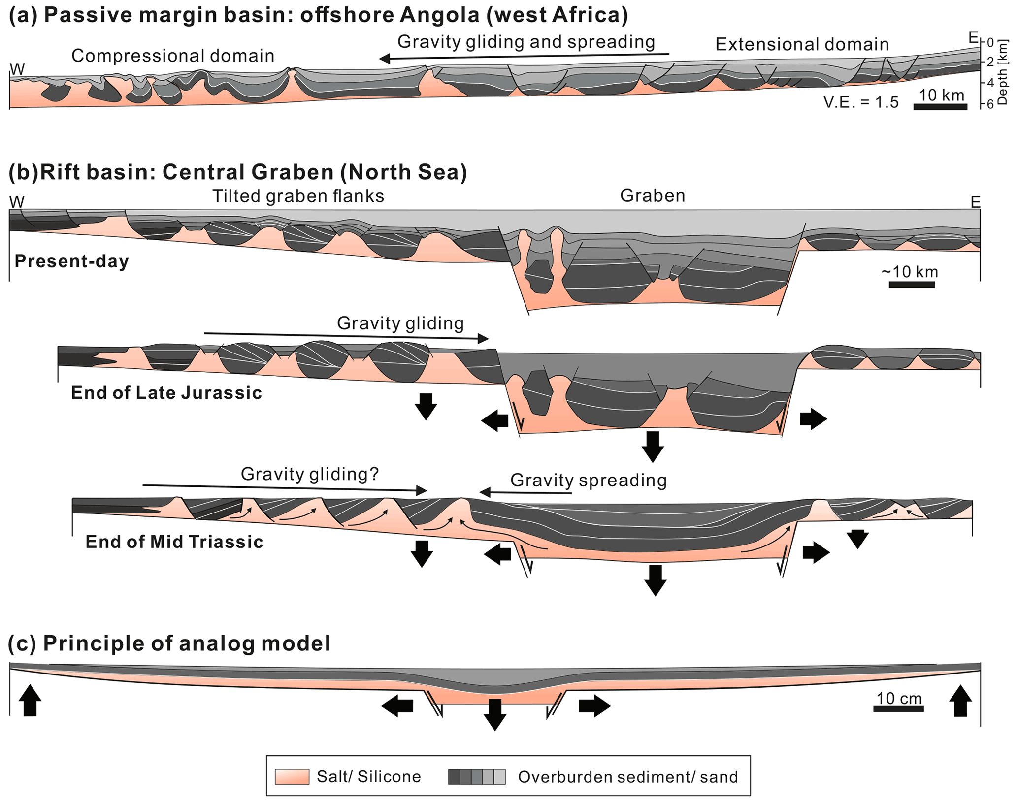
Figure 1(a) Geological cross section of the Angolan passive margin, where basinward-directed gravity gliding and spreading lead to the formation of an upslope extensional and a downslope compressional domain (Fort et al., 2004). (b) Schematic evolution of the structure and the salt flow patterns in the Central Graben (North Sea) (modified from Stewart and Clark, 1999). It is suggested that gravity gliding above the tiled western flank of the graben coincided with upward salt flow from the graben centre towards the rift shoulders (Penge et al., 1999). (c) Conceptual sketch of the experimental setup applied in this study. Graben extension is simulated by a vertically moving central block and two laterally moving flanks. Tilting of the flanks (due to thermal subsidence) is modelled by upward bent plates. α – angle of the salt base; V.E. – vertical exaggeration.
Driving processes of salt flow are well explained for salt-bearing passive margin basins, e.g. the Lower Congo Basin, Western Mediterranean, and the Santos Basin (Fort et al., 2004; Quirk et al., 2012; Jackson et al., 2015; Mianaekere and Adam, 2020), where both driving factors mostly act in the same seaward direction (Fig. 1a) (e.g. Brun and Fort, 2011; Peel, 2014). Scaled laboratory experiments focusing on passive margin salt tectonics reveal that seaward-directed tilting of the basin floor and/or sediment progradation typically cause the formation of a downdip compressional and an updip extensional domain (Fig. 1a) (e.g. Jackson and Cramez, 1989; Mauduit et al., 1997; Brun and Mauduit, 2009; Brun and Fort, 2011; Ge et al., 2019b). The initiation of gravity gliding and spreading depends on the angle of the basin slope and of the top surface (e.g. Vendeville, 2005; Rowan et al., 2012); i.e. the gravitational potential has to be sufficient to overcome the compressional, frictional strength of the overburden strata at the foot of the slope (Rowan et al., 2004).
In salt-bearing rift basins (SBRBs), these driving forces mostly act oppositely (Fig. 1b). On one side, the sedimentary regime in SBRBs is commonly characterized by aggradation with maximum sediment thickness in the basin centre and less sedimentation or erosion at the basin margins. In many SBRBs, such as the Glückstadt Graben (northern Germany), the Central Graben (North Sea), and the Polish Basin (Central Poland) (Penge et al., 1999; Stewart, 2007; Krzywiec, 2004), salt is almost completely evacuated from the basin centre towards diapirs on the basin flanks, whereas the graben centre is filled up with several kilometres of syn-kinematic sediments (Krzywiec, 2004; Maystrenko et al., 2005; Warsitzka et al., 2017). This evacuation was likely driven by upward-directed gravity spreading due to sedimentary loading (Hudec and Jackson, 2007; Warsitzka et al., 2018). Conversely, the graben flanks are often inclined towards a basin centre mainly due to thermal subsidence and flexural loading (e.g. Buchanan et al., 1996) causing basinward-directed stresses. Downward gravity gliding is often inferred from the occurrence of a domain of thin-skinned extensional structures at the upslope basin margin (e.g. Penge et al., 1999; Geil, 1991; Stewart and Coward, 1995; Best, 1996; Withjack and Callaway, 2000; Thieme and Rockenbauch, 2001; Mohr et al., 2005; Jackson and Larsen, 2009; Tvedt et al., 2013; Vackiner et al., 2013; Labaume and Teixell, 2020). For instance, in many rift basins in the central and southern North Sea, such as the Central Graben, the southern Viking Graben, and the Sole Pit Basin (e.g. Hughes and Davison, 1993; Stewart and Coward, 1995; Jackson and Larsen, 2009), thin-skinned rollovers and separated blocks (“rafts”) are observed above the tilted outer platforms of the rift basins (Hodgson et al., 1992; Buchanan et al., 1996; Penge et al., 1999; Stewart, 2014). It is suggested that these structures formed by a combination of gravitationally and tectonically driven extension (“rift–raft tectonics”) (Stewart and Clark, 1999; Penge et al., 1999) and, in some cases, coincided with thin-skinned shortening in the basin centre (e.g. Hughes and Davison, 1993; Coward and Stewart, 1995; Stewart and Coward, 1995). However, it is unclear how gravity gliding can take place during sediment aggradation in the basin centre because thick overburden sediments may act as a resisting buttress against gravity gliding. The oppositely acting processes of gravity spreading and gliding in SBRBs prompt the question of which geological configurations have to be fulfilled to initiate gravity gliding in the case of SBRBs; i.e. which minimum topographic gradient and basin slope is required? Furthermore, it is unclear how gravity gliding affects basin-wide salt flow and the evolution of salt structures in SBRBs and which driving process prevails at what period of the basin evolution.
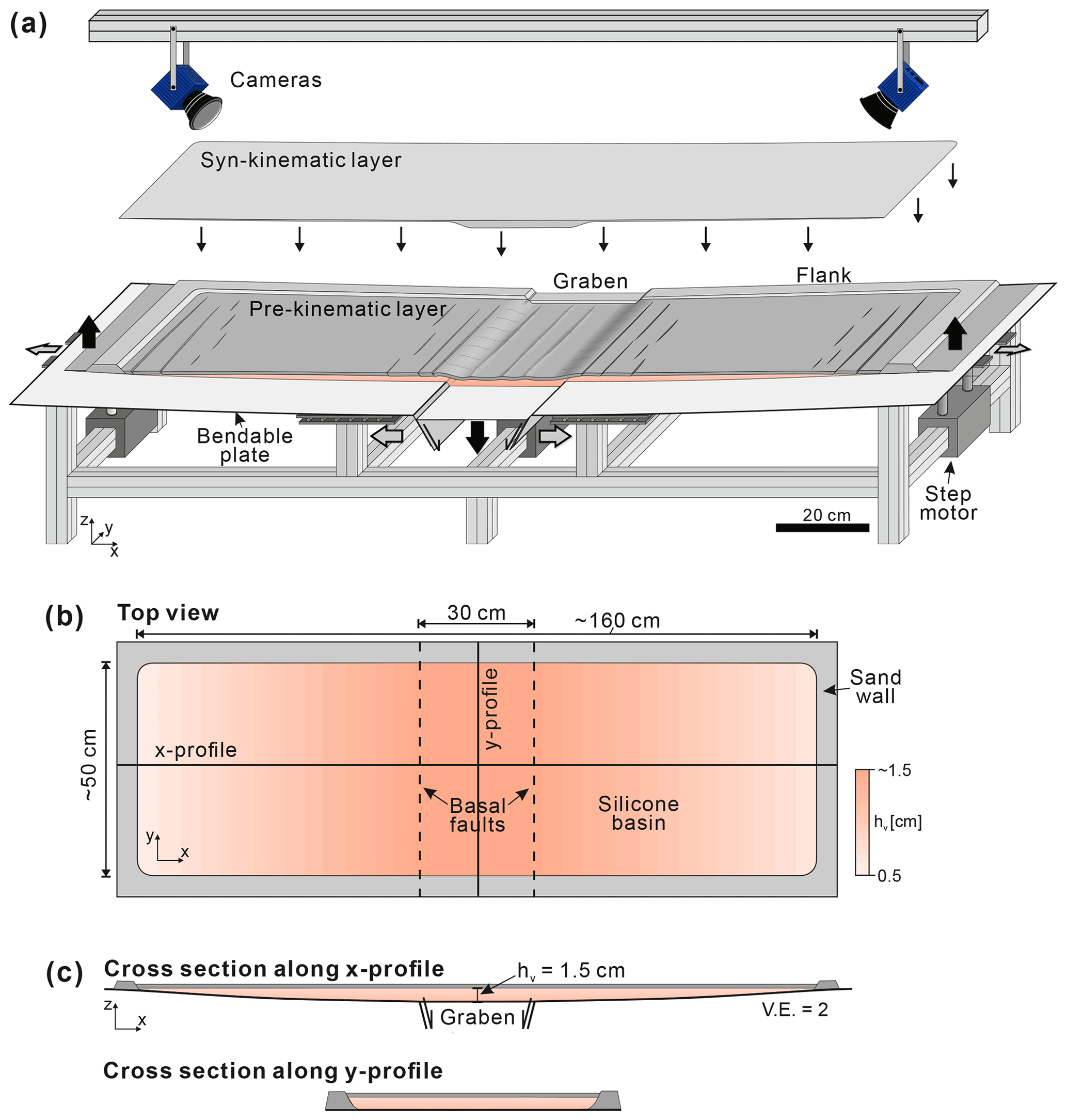
Figure 2(a) Sketch of the experimental setup. The apparatus consists of a central, vertically moving graben structure bounded by two bendable metal plates. The latter can be moved laterally and their outer edges can be uplifted. All parts can be controlled separately. The experimental surface is monitored by two stereoscopic cameras from above and images are utilized for 3D digital image correlation (Adam et al., 2005). Black arrows denote active movement of the basal parts driven by motors (i.e. downpull of the central graben and uplift at the outer edges of the flanks), and grey arrows display passive movement (i.e. lateral push of the flanking plates). (b) Top view of the silicone basin, which is confined by sand walls. (c) Cross section views of the initial silicone layer, which is covered by a 3 mm thick pre-kinematic sand layer (not shown in b). V.E. – vertical exaggeration.
Analogue models dedicated to the opposing interplay between gliding and spreading in SBRBs show that salt flows downward if the depocentre above the downthrown block is underfilled and returns to upward-directed flow as soon as syn-kinematic sediments are accumulated in the depocentre (e.g. Vendeville et al., 1995; Koyi et al., 1993; Ge et al., 1997; Dooley et al., 2005; Burliga et al., 2012; Warsitzka et al., 2015; Lymer et al., 2018; Roma et al., 2018; Dooley and Hudec, 2020). Basin-scale models reproduced thin-skinned extensional structures occurring on the flanks of the graben resulting from the decoupling effect of the salt layer (Nalpas and Brun, 1993; Koyi et al., 1993; Dooley et al., 2005; Ferrer et al., 2014; Moragas et al., 2017). Other experiments demonstrated how progradation of sedimentary wedges across extensional systems modifies sedimentary patterns in the overburden by introducing an additional component of gravity spreading (Loncke et al., 2010; Rojo et al., 2020). However, the influence of basin-scale tilting of the graben flanks and, hence, the effects of gravity gliding, on the evolution of supra-salt sedimentary structures and salt flow patterns have not been investigated yet.
The key motivation of this work is to evaluate the influence of regional-scale gravity gliding on salt flow processes and the tectono-sedimentary evolution of SBRBs. We designed a new experimental apparatus for analogue modelling to integrate the simulation of crustal-scale extension and tilting of the graben flanks. Here, the basic concept of the apparatus and results of preliminary experiments are presented. Based on the techniques of digital image correlation, we compare displacement and strain patterns between different scenarios: (1) only extension, (2) only tilting of the flanks, (3) combined extension and tilting, and (4) extension, tilting, and syn-kinematic sedimentation. In order to demonstrate the effect of a viscous detachment, these scenarios were performed with and without a viscous substratum. The experimental results illustratively demonstrate the functionality of the apparatus and reveal the first main differences between rift basins with tilted flanks and those surrounded by flat flanks.
Lagabrielle et al. (2010); Saspiturry et al. (2019); Labaume and Teixell (2020)Martín-Martín et al. (2017); Moragas et al. (2017); Troudi et al. (2017); Vergés et al. (2017)Bodego and Agirrezabala (2013); López-Mir et al. (2015); Saura et al. (2016); Cámara (2020)Hodgson et al. (1992); Høiland et al. (1993); Buchanan et al. (1996); Penge et al. (1999); Duffy et al. (2013)Tanveer and Korstgård (2009); Ge et al. (2017)Geluk (2005); Wong et al. (2007); Van Winden et al. (2018)Kusznir et al. (1996); Stovba et al. (1996); Stovba and Stephenson (2003)Seni and Jackson (1984)Lewis et al. (2013); Tvedt et al. (2016); Jackson and Lewis (2016); Ge et al. (2017)Radies et al. (2005); Baldschuhn et al. (2001); Strozyk et al. (2017)Maystrenko et al. (2005, 2017); Warsitzka et al. (2017)Pascoe et al. (1999); Dooley et al. (2003); Coleman et al. (2017)Vejbæk (1990); Best et al. (1983); Kockel et al. (1995)Van Gent et al. (2011); Strozyk et al. (2014)Rasmussen et al. (1998); Alves et al. (2002); Pena dos Reis et al. (2017)Jensen and Sørensen (1992); Koyi et al. (1995); Nilsen et al. (1996); Rowan and Lindsø (2017); Rojo et al. (2019)Vejbæk (1990); Geil (1991); Petersen et al. (1992); Clausen and Pedersen (1999); Jackson and Lewis (2016)Ferrer et al. (2008); Jammes et al. (2009, 2010); Ferrer et al. (2012)Dadlez et al. (1995); Wagner et al. (2002); Krzywiec (2004); Krzywiec et al. (2017)Mitchell et al. (1992); Heaton et al. (1995); Augustin et al. (2014)Dancer et al. (1999); O’Sullivan et al. (2021)Walker and Cooper (1987); Hughes and Davison (1993); Stewart and Coward (1995)Thomas and Coward (1996); Jackson and Larsen (2009); Jackson et al. (2019)Chapman (1989)Table 1Literature-based data compilation of worldwide salt-bearing rift basins. The thickness of the salt layer refers to the estimated maximum thickness of the original evaporitic layer. The pre-kinematic layer is defined as the sedimentary layer accumulated after the salt deposition and before the first post-salt rifting phase. ∗ Denotes basins in which gravity-driven salt tectonics has been proposed or proofed.
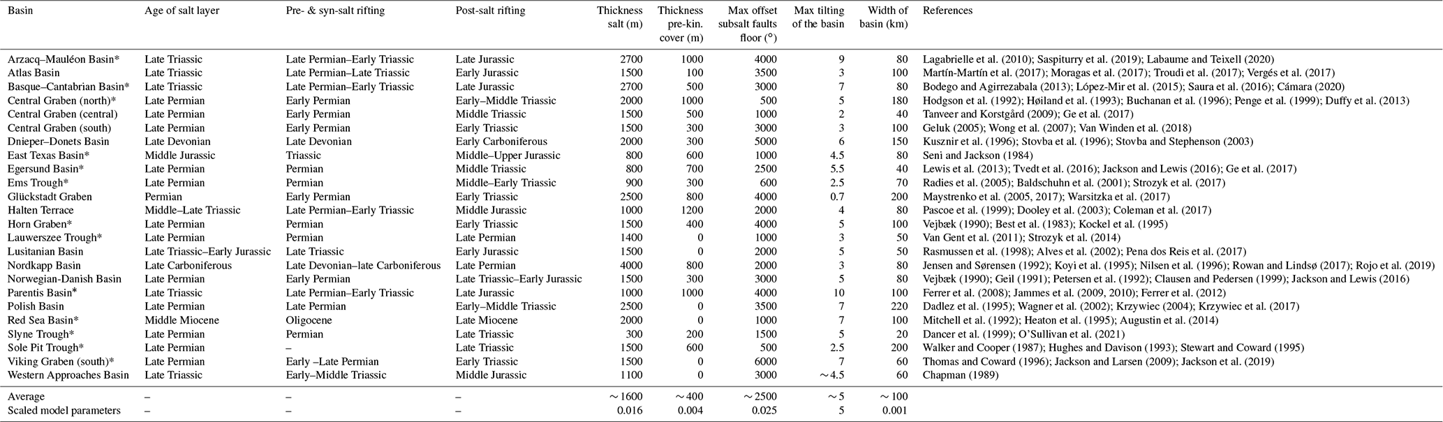
The experimental setup and the procedure are inspired by a generalized natural salt-bearing rift basin (Fig. 1c). Boundary conditions and basin configurations, such as age and thickness of the salt layer, timing of rifting, thickness of the pre-kinematic overburden, maximal amount of tilting, and fault displacement as well as basin width, were derived from a survey of various SBRBs worldwide (Table 1). In most basins, the initial phase of rifting occurred prior to the deposition of the major salt layer and in some case continued during deposition. The early post-salt evolution (∼ 10 to 20 Myr after salt deposition) is usually characterized by multiple phases of rifting each followed by post-rift thermal subsidence. Thermal relaxation and sedimentary loading usually cause subsidence in a wider region compared to that of the stretched extensional graben (Watts et al., 1982). We assume that these subsidence processes are the main drivers for the basinward tilting of the graben flanks. Such tilting can be as much as 10∘ (4.5∘ in average; Table 1). The supposed maximal thickness of the original salt layer in the basin centre ranges between 600 and 4000 m (1600 m in average) but pinches out towards the basin margins. The pre-kinematic layer (∼ 400 m in average; Table 1) is defined as the post-salt overburden deposited prior to the first post-salt extensional phase. In some basins, there was probably no pre-kinematic overburden because syn-salt rifting continued after end of salt deposition. The lithology of the pre-kinematic overburden can be fine- or coarse-grained clastics or carbonates. Therefore, we assume an averaged lithological composition when relating physical properties between the model and nature (see below).
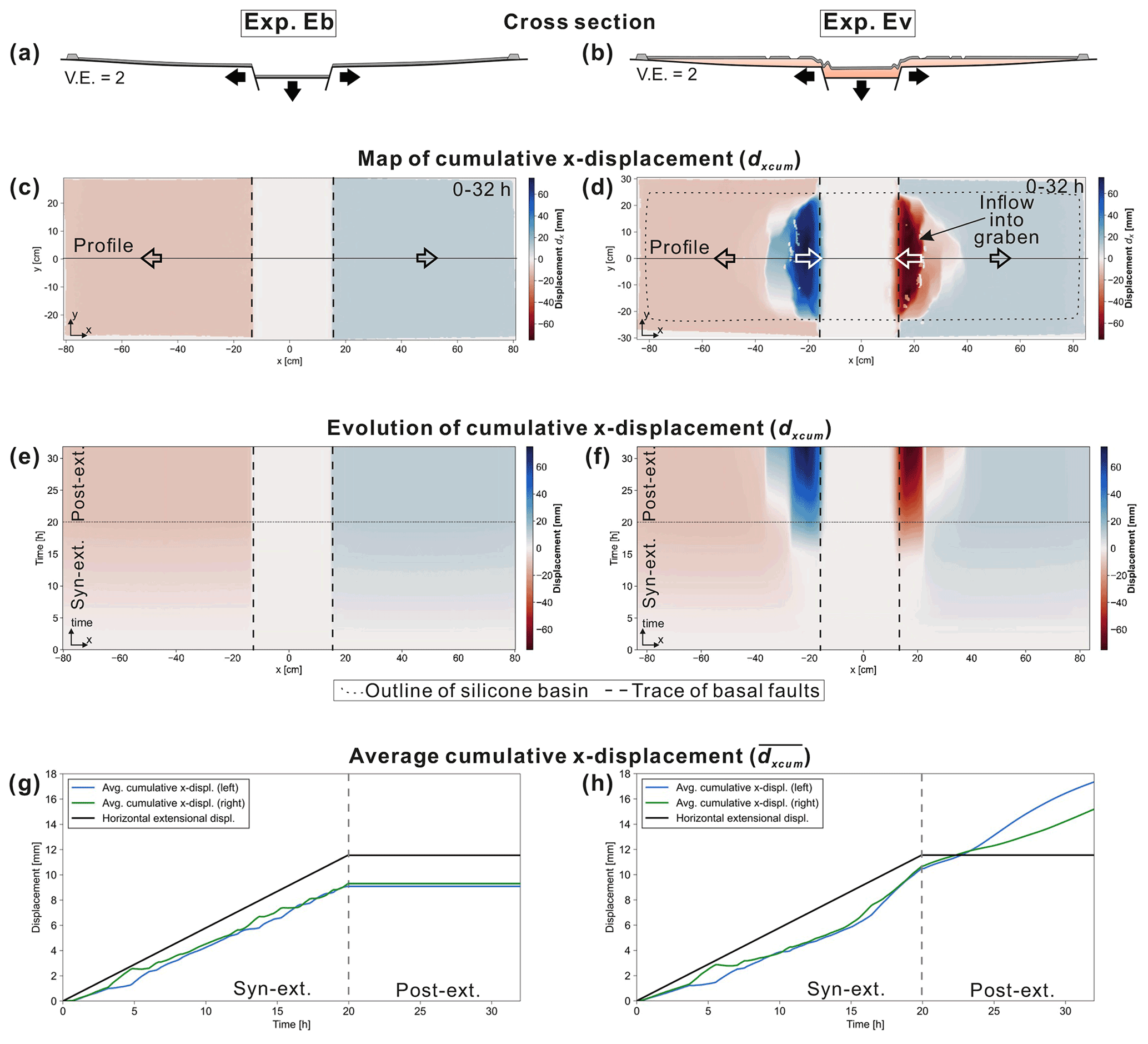
Figure 3Results of the DIC of experiment Eb (without viscous substratum) and Ev (with viscous substratum) in which only basal extension with a rate of 1 mm h−1 was applied. The total vertical displacement of the central block de was 2 cm. (a, b) Schematic cross sections through the centre of the experiments showing the final structures. (c, d) Top view of the cumulative x displacement dxcum at the end of the experiment (32 h). Blue colours reflect rightward and red colours leftward movement. (e, f) Evolutionary plots of dxcum for experiment Eb and Ev, respectively, extracted from a central profile (shown in c and d) and plotted against experimental time. (g, h) Averaged cumulative x displacement for the left (blue) and the right (green) half of the box plotted against experimental time. Note that the black line displays the lateral extension (max ∼ 12 mm per side), which is less than the vertical movement of the central block (max 20 mm). Furthermore, is slightly less (∼ 9 mm) than the horizontal extensional displacement of the graben flanks because the calculation of also includes the area above the horizontally stable graben centre.
3.1 Experimental setup
The experimental setup combines two main approaches of previous analogue modelling studies: (1) the simulation of upper crustal extension (e.g. Koyi et al., 1993; Dooley et al., 2005; Ferrer et al., 2014; Moragas et al., 2017; Roma et al., 2018) and (2) the effect of basin-scale tilting of the basin floor as it was applied to model salt tectonics at passive margins (e.g. Mauduit et al., 1997; Fort et al., 2004; Dooley et al., 2017; Ge et al., 2019b). The apparatus consists of a ∼ 30 cm wide, rigid graben block, which is bounded by two 60∘ faults and can be moved vertically by a step motor (Fig. 2a). The graben flanks are made of ∼ 100 cm long (x axis) and 60 cm wide (y axis) bendable plates, which are pushed outward by the down-going central block to simulate tectonic extension. The dimensions of the apparatus are chosen to simulate the wide range of variably sized rift basins with a maximal extent of ∼ 220 km (Table 1). Besides the lateral movement, the outer edges of the flanks can be uplifted by independently controlled step motors so that the plates are bent and tilted. Thermal subsidence in nature leads to widespread, saucer-shaped subsidence of the basin. However, the net effect of thermal subsidence is differential vertical movement between the graben centre and the flanks, which is here mimicked by an uplift of the flanks. The flanking plates are made of 4 mm thick steel and vertically supported at the footwall tips of the basal faults. This ensures that neither downpull of the graben block nor the loading of the analogue materials leads to flexural bending of the plates in the basin centre. In the presented experiments, the silicone basin extends over an area of roughly 160 × 50 cm and is confined by sand walls (Fig. 2b). The width of the silicone basin (y axis) is sufficient to reduce boundary effects The silicone layer is thickest in the basin centre (hv = ∼ 1.5 cm) and pinches out towards the basin margins (Fig. 2c).
The experimental surface is recorded by two stereoscopic CMOS (complementary metal-oxide semiconductor) sensor cameras (“Imager M-lite 12M camera”, 12-bit monochrome, 12 MP resolution) in top view to analyse the evolution of the surface displacements and strains (Adam et al., 2005). Images are acquired at intervals of 300 s and processed by the StrainMaster© (LaVision GmbH) 3D digital image correlation (DIC) software (Adam et al., 2005; LaVision, 2018). The 3D-DIC analysis is an optical, non-intrusive method to determine shapes, displacement, and deformation in sub-millimetre resolution.
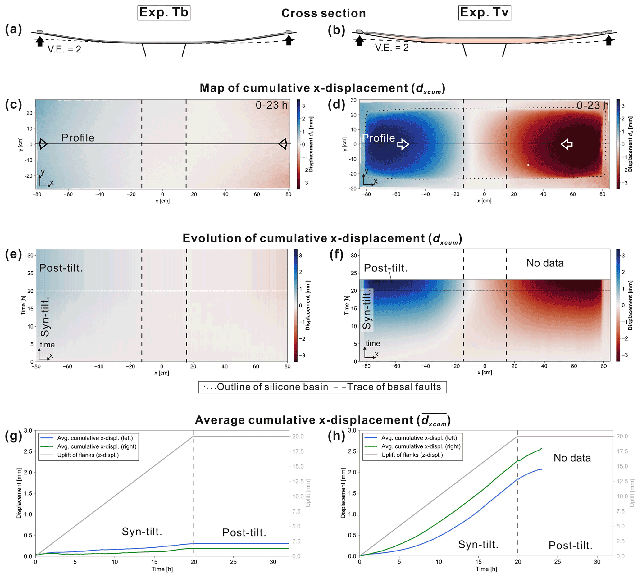
Figure 4Results of the DIC of experiment Tb (without viscous substratum) and Tv (with viscous substratum) in which tilting was applied with a rate of 1 mm h−1. The total vertical displacement of the outer edges of the flanking plates was 2 cm, which caused a maximum tilting of ∼ 5∘. (a, b) Schematic cross sections through the centre of the experiments showing the final structures. (c, d) Top view of the cumulative x displacement dxcum at the end of the experiment (23 h). Blue colours reflect rightward and red colours leftward movement. (e, f) Evolutionary plots of the cumulative x displacement dxcum for experiment Tb and Tv, respectively, extracted from a central profile (shown in c and d) and plotted against experimental time. (g, h) Averaged cumulative x displacement for the left (blue) and the right (green) half of the box. The grey line presents the uplift of the flanks, which was equal for both sides. Note that the results shown of Tv are shorter than in other experiments, since no data are available after 23 h.
3.2 Experimental materials
The viscous behaviour of salt (e.g. Urai et al., 2008) is simulated by a silicone putty (polydimethylsiloxane, PDMS) of the type KORASILON G 20 OH sold by the company Kurt Obermeier GmbH & Co. KG. The rheology of this silicone is equivalent to that of KORASILON G 30 M, which was characterized by rheometer tests (RC20.1-CPS-P1, RheoTec) at the Helmholtz Centre Potsdam GFZ German Research Centre for Geosciences (Rudolf et al., 2016). The dynamic viscosity is 2.2–2.8 × 10⁴ Pa s, which is slightly temperature-dependent (decrease of 1.4 %–1.9 % per 1 K increase), and the density is 970 kg m−3 at 25∘C. It has a Newtonian behaviour at low strain rates (< 10−2) and a strain rate softening behaviour above relatively high strain rates (> 10−2 s−1) (Rudolf et al., 2016).
Frictional–plastic behaviour of overburden sediments is modelled by granular mixtures of quartz sand (bulk density = 1620 kg m−3) and silicate cenospheres (bulk density = 430 kg m−3). In order to adapt the density ratio between the viscous silicone and the overburden sand to match the natural density ratio, various mixtures of both granulates were used (see Appendix B for details). Similar to upper crustal rocks, such granulates deform according to the Mohr–Coulomb failure criterion (Eq. A3, see Appendix A) (Lohrmann et al., 2003; Panien et al., 2006). Frictional properties (coefficient of internal friction μ, cohesion C; Table B1) and densities of the mixtures were determined in ring shear tests in the laboratory of the Helmholtz Centre Potsdam GFZ German Research Centre for Geosciences. Details of the measurements and the material properties can be found in Warsitzka et al. (2021b).
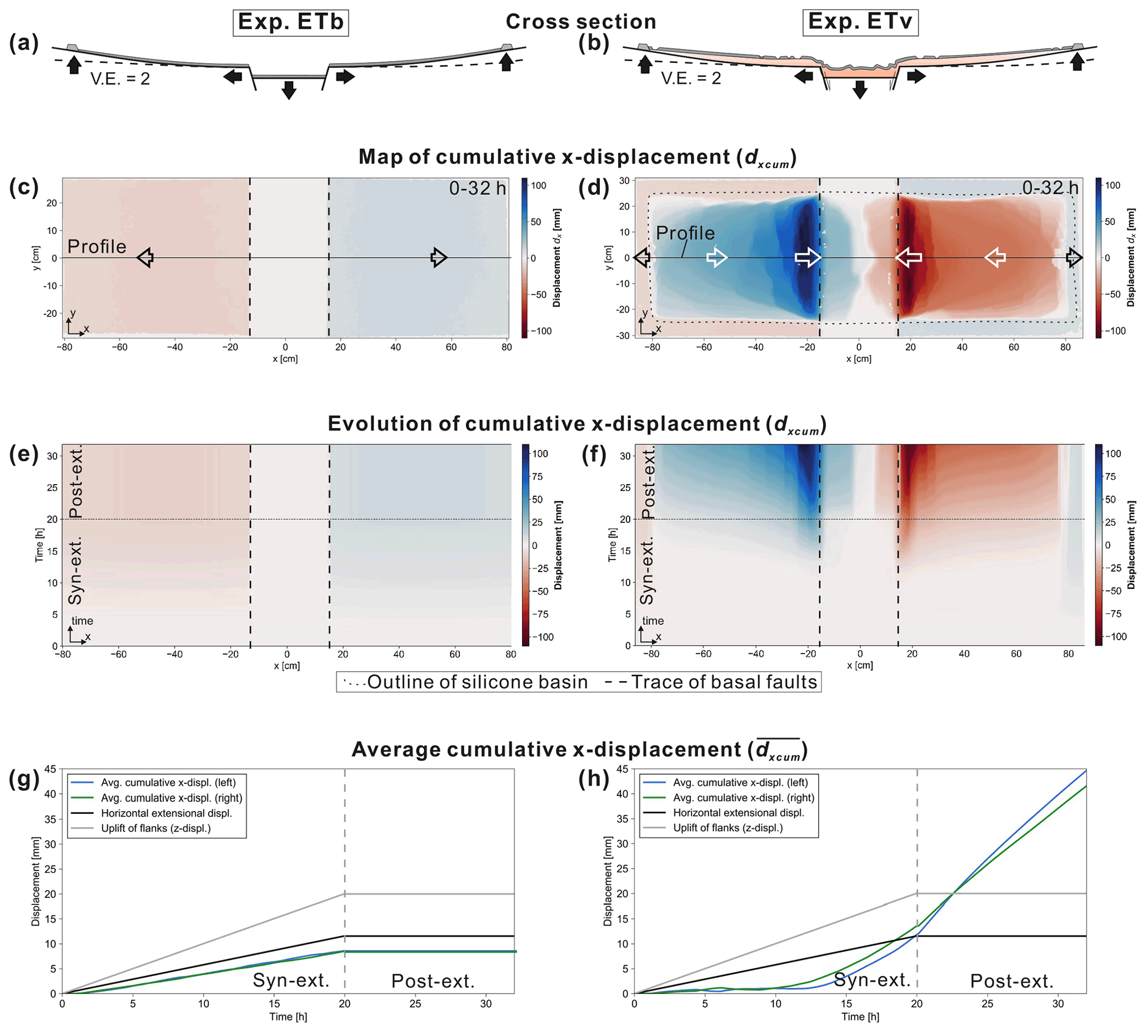
Figure 5Results of the DIC of experiment ETb (without viscous substratum) and ETv (with viscous substratum). In both experiments extension and titling with rates of 1 mm h−1 were applied. The total vertical displacement of the central block and the flanking plates was 2 cm. The maximum tilting of the flanks at the outer edges was ∼ 5∘. (a, b) Schematic cross sections through the centre of the experiments showing the final structures. (c, d) Top view of the cumulative x displacement (dxcum) at the end of the experiment (32 h). Blue colours reflect rightward and red colours leftward movement. (e, f) Evolutionary plots of the cumulative x displacement dxcum for experiment ETb and ETv, respectively, extracted from a central profile (shown in c and d) and plotted against experimental time. (g, h) Averaged cumulative x displacement for the left (blue) and the right (green) half of the box. Furthermore, is less (∼ 8 mm) than the horizontal extensional displacement of the graben flanks because the calculation of also includes the area above the horizontally stable graben centre.
3.3 Scaling
In order to relate geometrical, dynamical, kinematical, and rheological model parameters to the natural prototype, we applied standard scaling procedures (Hubbert, 1937; Ramberg, 1981; Davy and Cobbold, 1991; Weijermars et al., 1993), which are described in detail in Appendix A. The geometrical scaling ratio is set to 10−5 meaning that 1 cm in the model represents 1 km in nature (Table B1, Appendix A). Principles of dynamical scaling require that driving and resisting forces acting during deformation have to be related properly (Weijermars and Schmeling, 1986; Pollard et al., 2005). Drivers for salt flow as simulated in our models are produced by gravitational buoyancy forces due to the loading of sediments on top of the salt layer and by tectonically driven lateral pressure forces (Jackson and Hudec, 2017). Resisting forces result from the frictional strength of the brittle overburden and viscous stresses in the substratum (Jackson and Hudec, 2017). For dynamic similarity, we relate these forces in the “brittle–viscous coupling” (BVC), which is the ratio between frictional forces in the overburden and viscous forces in the substratum, and the “Argand number” (Ar), which is the ratio between the buoyancy forces and the tectonic forces (Schueller and Davy, 2008). As shown in Fig. B2 (Appendix A), both ratios are similar between the model and nature so that the models can be regarded as dynamically scaled. Based on the dynamical scaling (i.e. the relationship between stresses and viscosity of the substratum) and the geometrical scaling ratio, we can define the velocity scaling ratio (∼ 10−4, Table B1). Natural extension rates vary between 0.1 and 10 mm a−1 requiring that experimental extension rates should be in the range of ∼ 0.1 to 10 mm h−1. In the models presented here, we choose an intermediate rate of 1 mm h−1 (Table 2) for practical reasons so that a simulation duration of several hours is achieved.
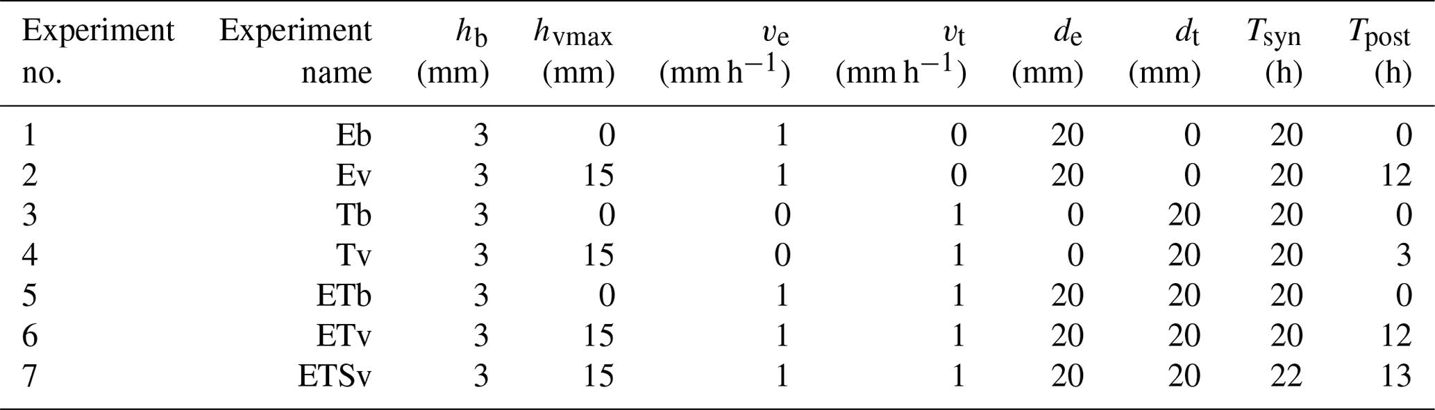
Table 2Experiments and key parameters. In an experiment's name, E stands for extension, T for tilting, S for syn-kinematic sedimentation, b for (only) brittle, and v for viscous. de – total amount of vertical displacement of the graben centre; dt – total amount of vertical uplift of the graben flanks; hb the thickness of the pre-kinematic sand layer; hvmax – maximum thickness of the silicone in the basin centre; Tsyn – duration of the syn-deformation phase (extension and/or tilting); Tpost – duration of the post-deformation phase; ve – (vertical) extension rate; vt – uplift rate of the flanks. See Fig. B1 for illustration of the parameters.
3.4 Experimental procedure
Since all parts of the apparatus can be controlled separately, different modes of basin evolution can be tested, such as pure basal extension, pure tilting of the flanks, and simultaneous basal extension and tilting (Table 2). The latter scenario refers to the geological condition that in most rift basins salt was deposited during or after an initial rifting phase (Table 1). Hence, it can be assumed that early post-salt history is characterized by thermal sag basin subsidence accompanied by additional post-salt rifting.
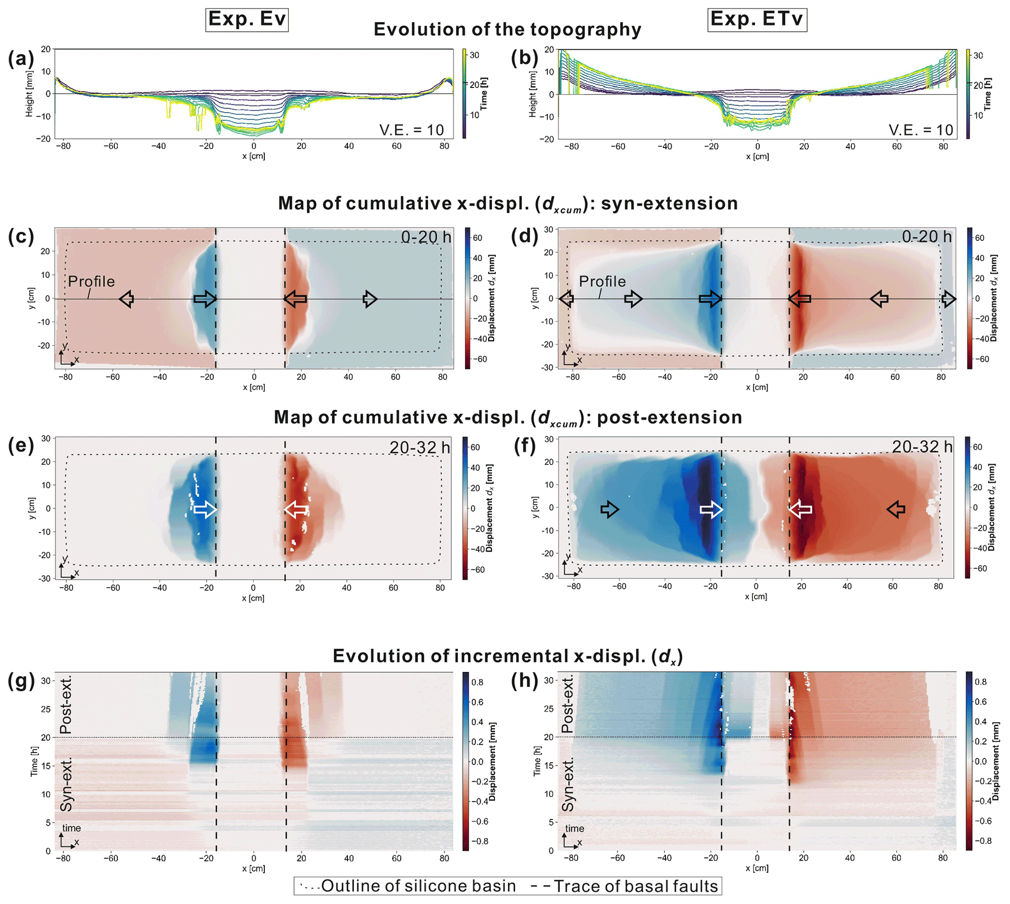
Figure 6Comparison of displacement patterns between experiment Ev (only extension) and ETv (extension and tilting). (a, b) Evolution of the topography. Along a central profile (see c and d), the elevation of the experimental surface was extracted every 2 h. The artefacts in the lines result from exposed reflective silicone, which disturbs the DIC analysis. (c, d) Cumulative x displacement dxcum of the syn-extensional phase. (e, f) Cumulative x displacement dxcum of the post-extensional phase. (g, h) Evolutionary plots of the incremental x displacement dx extracted along a central profile (shown in c and d) and plotted against the experimental time. Blue means rightward and red leftward movement.
In a first series of experiments (“brittle-only experiments”: Eb, Tb, ETb), no silicone layer was included in order to present benchmark experiments for the displacement patterns of the basal parts and to better illustrate the effects of the viscous layer in subsequent experiments. In experiments including a silicone layer (“brittle–viscous experiments”: Ev, Tv, ETv, ETSv), the silicone layer was covered by an even, ∼ 3 mm thick layer of granular material (bulk density = ∼ 850 kg m−3) prior to the onset of deformation (“pre-kinematic layer”). In experiments in which basal extension was applied, the central graben block (Fig. 2) was pulled down with a rate of ve = 1 mm h−1 to a maximum vertical displacement of de = 20 mm (Table 2). This downward pull pushed the graben flanks outward up to maximum horizontal extensional displacement of 12 mm per side. In experiments with tilting, both flanks were uplifted with a rate of vt = 1 mm h−1 to a maximum vertical displacement of dt = 20 mm at the outer edges of the flanks (Table 2). This caused a parabolic bending of the flanking plates resulting in a maximum tilting angle of α = 5∘ at the margins of the silicone basin and a tilting of ∼ 1.5∘ on average across the entire flank. In experiments with a viscous layer, the syn-extensional or syn-tilting phase was followed by a phase in which we continued to monitor the surface deformation resulting from ongoing flow of the silicone (Tpost; Table 2). Note that Tpost in experiment Tv is shorter than in the other experiments due to the lack of data in this experiment.
For most experiments, no syn-kinematic sand sedimentation was applied to demonstrate the deformation patterns resulting only from the specific mode. Only ETSv involves all relevant processes, which should be investigated with this apparatus (extension, tilting, syn-kinematic sedimentation). At intervals of 5 h, syn-kinematic sand was sieved on the model surface until the graben centre was completely filled up to the top of the sand cover above the footwall sides of the graben. Subsequently, a syn-kinematic sand layer with a uniform thickness of ∼ 1 mm was added on the entire area of the silicone basin (Fig. 2a). The total volume of the syn-kinematic layer was the same in each sedimentation interval, whereas its density was gradually increased according to the procedure described in Appendix B. This sieving procedure is aimed to mimic aggradational sedimentation pattern as observed in most continental basins. Due to interruptions during sieving, the experimental duration of experiment ETSv is longer than in the other experiments (Table 2). After finishing experiment ETSv and soaking the sand layers with water, cross sections were cut and photographed in order to examine internal, syn-kinematic structures.

Figure 7Comparison of strain patterns between Ev (only extension) and ETv (extension and tilting). (a, b) Cumulative normal strain in x direction exxcum of the syn-extensional phase. (c, d) exxcum of the post-extensional phase. Curved fault zones and minor strain close to the long sides of the silicone basin represent boundary effects resulting from drag at the sidewalls. (e, f) Evolutionary plots of the incremental x-normal strain exx extracted along a central profile (shown in c and d) and plotted against the experimental time. Blue means extensional and red compressional strain. (g, h) Top-view photographs of deformation structures close to the central graben at the end of the experiment.
In the following, we compare experiments, which were conducted without a viscous silicone layer (Eb, Tb, ETb) with those containing a viscous substratum (Ev, Tv, ETv). Then, we show differences in displacement and strain patterns between the brittle–viscous experiment with only extension (Ev) and the experiment with extension and tilting (ETv). Finally, the experiment including syn-kinematic sedimentation simultaneous to extension and tilting (ETSv) is presented.
4.1 With vs. without viscous substratum
4.1.1 Basal extension
When only basal extension was applied as boundary condition in experiment Eb (without viscous layer), both flanks were pushed apart laterally by the downward-moving central graben block (Fig. 3a and c). Except for straight fault zones above the basal normal faults, no further deformation structures could be observed in Eb. In experiment Ev (including viscous layer), basal extension caused deformation of the viscous substratum and the cover layer close to the graben, overprinting the outward-directed movement of the graben flanks (Fig. 3b and d). The cover layer moved inward (max 70 mm in 20 h) indicating an influx of silicone into the graben. The outer edges of the regions affected by inward movement are curved, which likely reflects boundary effects resulting from the drag along the sidewalls. Figure 3e and f display the evolution of the cumulative x displacement dxcum, which is the x displacement extracted from an x profile through the centre of the box and summed up over the experimental time. It shows that the inward movement in Ev began during the late stages of the syn-extensional phase (after ∼ 1.5 cm vertical displacement of the graben) and continued after extension stopped (post-extensional phase). Figure 3g and h display the averaged cumulative x displacement separately for the left (blue) and the right (green) half of the experimental surface. In both experiments, Eb and Ev, increased linearly with progressive lateral extension. However, towards the end of the extensional phase increased more strongly in Ev. This reflects the effect of the movement of the cover towards the graben structure, which was faster than the lateral extension. No further displacement occurred in Eb after the end of basal extension (Fig. 3g), whereas the displacement constantly increased in Ev during the post-extensional phase (Fig. 3h).
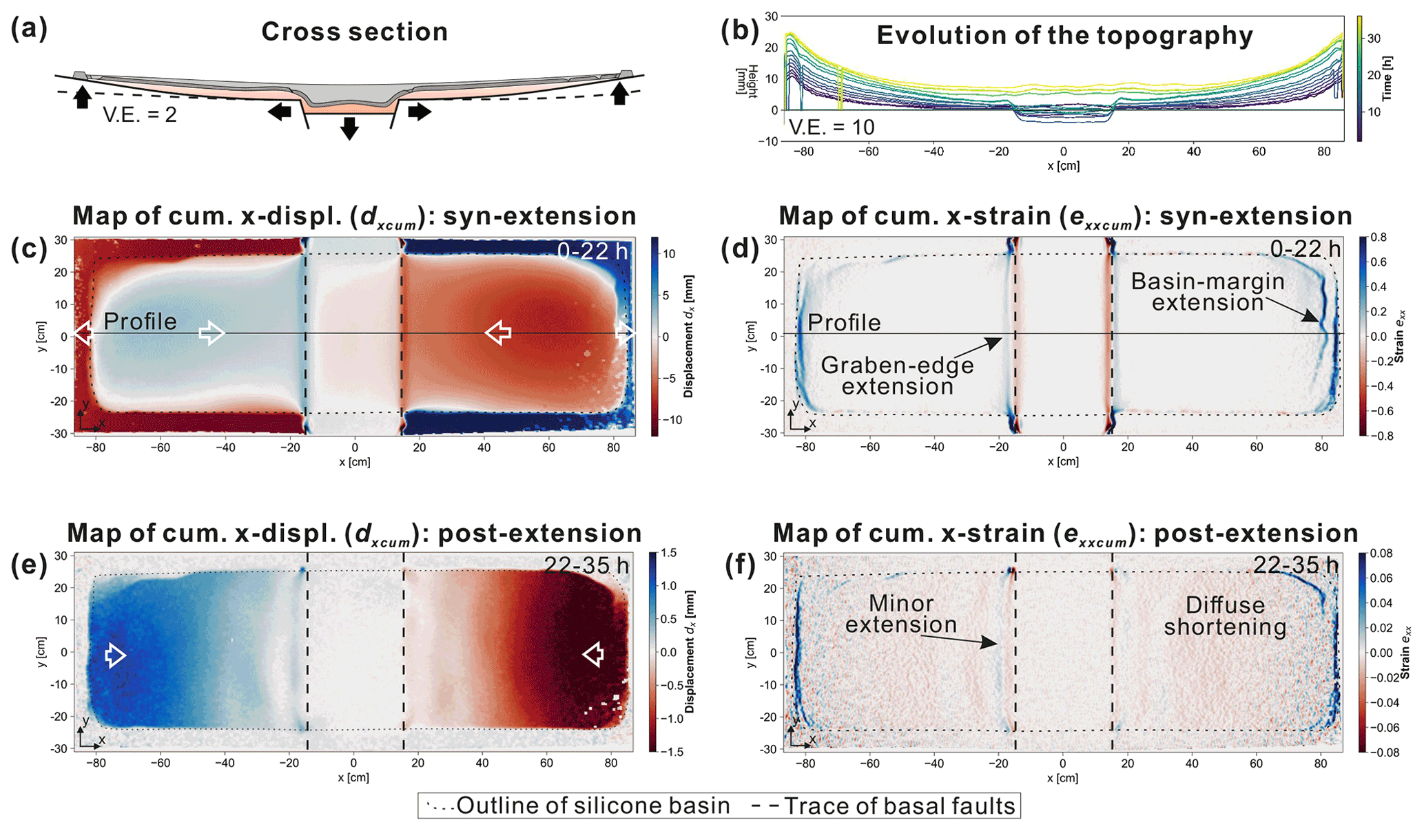
Figure 8Displacement and strain patterns of ETSv (extension + tilting + sedimentation). (a) Schematic cross section through the centre of the experiment showing the final structures. (b) Evolution of the topography. Along a central profile, the elevation of the experimental surface was extracted every 2 h. The artefacts in the lines result from exposed reflective silicone, which disturbs the DIC analysis. (c) Cumulative x displacement dxcum and (d) cumulative x-normal strain exxcum of the syn-extensional phase. (e) Cumulative x displacement dxcum and (d) cumulative x-normal strain exx of the post-extensional phase.
4.1.2 Flank tilting
In experiment Tb (without silicone) in which only tilting of the flanks was applied, minor x displacement can be observed at the margins of experimental surface resulting from rotational movement of the flanks (Fig. 4a and c). In experiment Tv (including a viscous layer), the tilting of the flanks caused a widespread movement of the brittle cover towards the centre of the box (max 3 mm in 20 h; Fig. 4d) indicating a downward redistribution of the silicone. Note that the amount of the horizontal displacement towards the graben is much less in Tv than in Ev (Fig. 3d). The evolutionary plot of the cumulative x displacement dxcum (Fig. 4f) shows that this downward movement began after a relatively small amount of tilting (∼ 1∘ after 5 h). The downward movement continued after the tilting stopped (Fig. 4f and h).
4.1.3 Extension and tilting
In experiments ETb and ETv, graben extension and flank tilting were applied simultaneously (Fig. 5a and b). In ETb, x displacement of the experimental surface is dominated by the lateral movement of the graben flanks (Fig. 5c and e) similar to the displacement patterns in Eb (Fig. 3c). With the presence of a viscous layer in ETv, the inward movement of the cover layer towards the subsiding graben affected the entire region of the uplifted flanks (Fig. 5d). Inward movement was at a maximum close to the basal normal faults (∼ 110 mm in 32 h) and reflects the downslope gliding of the cover and silicone. The evolutionary map shows that the downslope movement appears to have been activated at roughly half of the syn-extensional phase (∼ 1 cm of subsidence of the graben and ∼ 2.5∘ tilting of the flanks) (Fig. 5f). During the post-extensional phase of ETv, downslope gliding continued. The averaged cumulative x displacement increased strongly towards the end of the syn-extensional phase in ETv and still increased linearly during the post-extensional phase (Fig. 5h). This implies that the downward movement of the cover layer continued at a relatively high velocity.
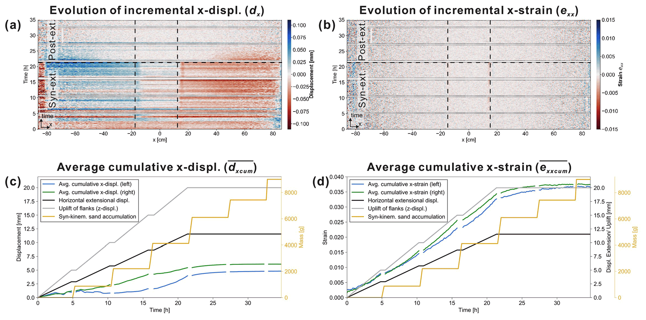
Figure 9Displacement and strain evolution of ETSv (extension + tilting + sedimentation). (a) Evolutionary plots of the incremental x displacement dx and (b) the incremental x strain exx extracted along a central profile (shown in Fig. 8c and d) and plotted against the experimental time. (c) Averaged cumulative x displacement and (d) averaged cumulative x strain for the left (blue) and the right (green) half of the box.
4.2 Flat vs. tilted flanks
4.2.1 Displacement patterns
The effects of tilted flanks on the structural development is evaluated by comparing experiments Ev (only extension) and ETv (extension + tilting) (Fig. 6a and b). The total amounts of x displacement dxcum were significantly higher and deformation affects a larger region if the flanks were tilted contemporaneously with basal extension (max syn- + post-extensional displacement dxcum = 82 mm in Ev and 110 mm in ETv; Fig. 6c and d). Particularly during the post-extensional phase, widespread downward movement occurred in the entire silicone basin in ETv, whereas deformation was limited to regions close to the basal graben in Ev (Fig. 6e and f).
In both experiments, the onset of inward movement above the graben flanks began towards the end of the syn-extensional phase and the regions affected by downward movement adjacent to the graben became wider after extension stopped (Fig. 6g and h). No displacement can be observed above the subsided graben block in Ev (Fig. 6g). In contrast, convergent movement began abruptly in the graben centre at the beginning of the post-extensional phase in ETv (Fig. 6h). This implies that influx into the graben centre is stronger when flank tilting is applied simultaneously with basal extension.
Note that the incremental movement of the graben flanks is not fully continuous and symmetrical during basal extension (Fig. 3g and h). This likely results from mechanical locking of the graben block on the basal faults.
4.2.2 Strain patterns
The strain patterns are analysed by means of the cumulative normal strain in x direction exxcum. Here, extensional strain is defined as positive and compressional strain as negative (Fig. 7). These patterns reveal that extensional fault zones developed above the footwall blocks of the graben ∼ 6 cm offset from the basal faults (“graben-edge extension”) in Ev (Fig. 7a). During the post-extensional phase, additional extensional zones were initiated further away from the basal normal faults at offsets of up to ∼ 12 cm (Fig. 7c), which gradually moved towards the central graben (Fig. 7e). Compressional strain, which accommodated the extensional strain, was focused in straight, narrow regions directly above the ramps of the basal faults. These compressional regions remained stable throughout the experiment and only slightly increased in width during the post-extensional phase (Fig. 7e).
In ETv, graben-edge fault zones were located closer to the basal faults during the syn-extensional phase (< 5 cm; Fig. 7b) than in Ev. Furthermore, the maximum amount of exxcum in these zones was smaller in ETv (∼ 1.5) than in Ev (∼ 2.5). Until the end of the post-extensional phase, the region affected by graben-edge extension migrated upslope and widened to roughly 13 cm on each side (Fig. 7d). Additional extensional fault zones occurred at the outer margins of the silicone basin (“basin-margin extension”; max exxcum = 1.2) (Fig. 7b and d). These migrated downslope and changed from straight to curved fault zones during the post-extensional phase (Fig. 7d and f). Similar to Ev, the compressional strain localized above the ramps of the basal faults in ETv during the syn-extensional phase (max exx = ∼ −1; Fig. 7f). However, after basal extension stopped, additional curved compressional zones developed above the hanging wall graben block in ETv (Fig. 7f and h), which is different from the post-extensional evolution in Ev (Fig. 7e and g).
In summary, syn-extensional flank tilting in ETv has the following effects on the overall deformation patterns: (1) the formation of basin-margin extensional fault zones, which gradually migrate downslope; (2) decreased amounts of extensional strain at the graben-edge fault zones; and (3) the formation of compressional zones (buckle folding) above the hanging wall graben block during the post-extensional phase.
4.3 Effects of syn-kinematic sedimentation
In ETSv, extension and tilting of the basal parts was accompanied by regular intervals of syn-kinematic sand accumulation (Fig. 8a and b). Similar to ETv (equivalent experiment without sedimentation; Fig. 6d and f), a downslope gliding of the overburden above the flanks can be observed (Fig. 8c). However, the total amount of cumulative x displacement dxcum at the end of the extensional phase is smaller in ETSv (max ∼ 10 mm) than in ETv (∼ 30 mm; Fig. 6d). This difference is even higher for dxcum of the post-extensional phase (ETSv: 1.5 mm, Fig. 8e; ETv: 60 mm, Fig. 6f). This implies that a sequential filling of the downslope depocentre with syn-kinematic sand significantly reduces downslope gliding of the cover.
Graben-edge extension and compressional strain in the graben centre were almost completely suppressed in ETSv (max exxcum = 0.2; Fig. 8d and f). The total amount of strain at the basin-margin extensional fault zones was also less (max exxcum = 0.8) than in ETv (max exxcum = 1.2; Fig. 7b and d). In ETSv, extensional strain was focused on 1–2 discrete zones and, hence, more localized compared to the widely distributed strain observed in ETv (Fig. 7f). During the post-extensional phase, downslope gliding was restricted to the upslope regions of the graben flanks (Fig. 8e). Diffuse, widespread compressional strain occurred in the central parts of the flanks (Fig. 8f) and not above the graben centre as in ETv (Fig. 7d).
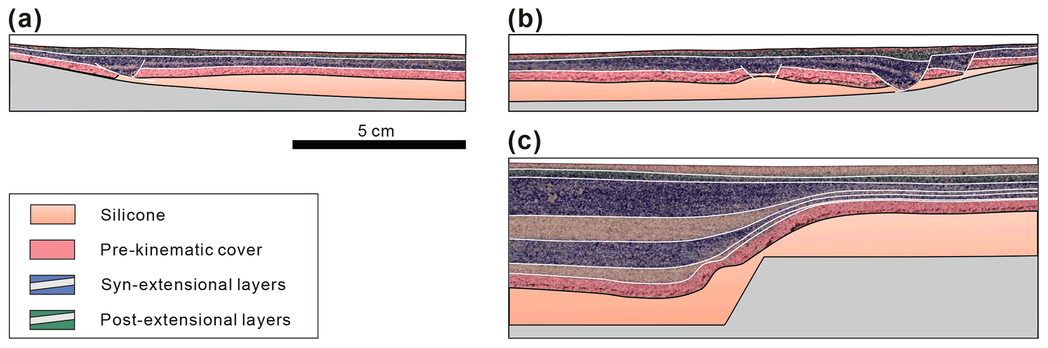
Figure 10Cross sections cut through the centre of ETSv in which syn-kinematic sand accumulation was applied during and after basal extension. (a) Cross section of the extensional fault zone at the left basin margin. (b) Cross section of the extensional fault zone at the right basin margin. (c) Cross section of the syn-kinematic strata close to the right basal fault. Structures above the left basal fault were similar.
The evolutionary plots in Fig. 9 show that most of the deformation occurred during the basal extension and rapidly decreased during the beginning of the post-extensional phase. This is also in contrast to ETv, where maximum amounts of displacement and strain were achieved during the post-extensional downslope gliding (Fig. 7f).
Cross sections cut through the final experiment reveal that the structures of basin-margin extensional fault zones in the sand cover are characterized by synthetic rollovers and symmetric grabens (Fig. 10a and b). The strongest deformation occurred directly at the pinch out of the silicone layer. Aside from minor extensional thinning of the pre-kinematic layer, no deformation structures are visible close to the basal faults (Fig. 10c). This indicates that strain of the graben-edge extensional zone is insufficient to produce significant faulting.
5.1 Experimental structures and kinematics
The presented experiments on gravity-driven deformation in salt-bearing rift basins (SBRBs) provide first insights into the influence of flank tilting on basin-wide deformation patterns in the brittle–viscous strata. When comparing brittle-only (Eb, Tb, ETb) and brittle–viscous experiments (Ev, Tv and ETv), it can be observed how the basal deformation is significantly overprinted if a viscous layer is present (Fig. 3, 4, and 5). In the brittle-only experiments, the deformation of the cover is directly coupled to the movement of the rigid basal parts (Fig. 11a). In contrast, the cover deformation is decoupled from the base in the brittle–viscous experiments leading to widespread lateral movement and the formation of distributed fault zones (Fig. 11b–e). Such insights into different deformation patterns, resulting from the rheological stratification, can also be obtained from lithosphere-scale rift models (e.g. Zwaan et al., 2019).
The comparison of the brittle–viscous experiments among each other demonstrates how local deformation structures due to a sub-salt graben are affected by regional-scale flow of the viscous material. When only basal extension is applied (Ev), deformation is restricted to the area in the vicinity of the basal graben (Fig. 11a). Distributed extensional fault zones in the cover developed offset from the basal normal faults above the footwall blocks of the graben. This implies that deformation in the cover layer was effectively decoupled from basal extension as it has been demonstrated by previous analogue modelling studies (Nalpas and Brun, 1993; Vendeville et al., 1995; Ge et al., 1997; Withjack and Callaway, 2000; Dooley et al., 2005; Zwaan et al., 2019).
When only tilting is applied (Tv), localized extension occurs at the basin margins, while diffuse shortening affects the cover in downslope regions (Fig. 11b). Such deformation patterns are similar to those in early post-salt phases of passive margin basins affected by slight, progressive tilting (Ge et al., 2019b).
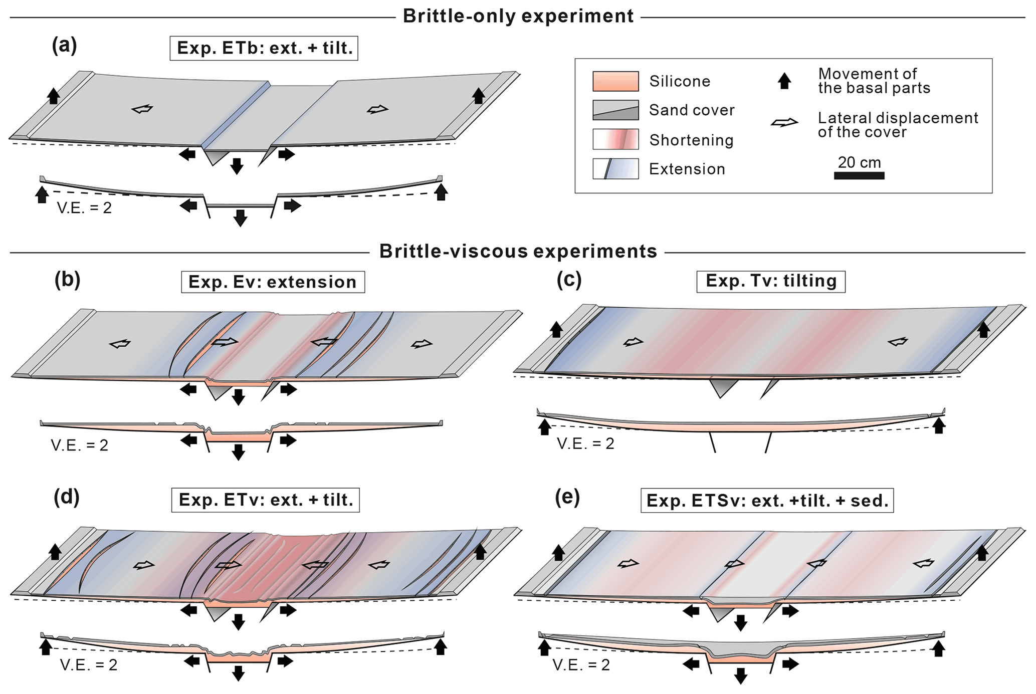
Figure 11Sketches summarizing the main results of this experimental study. (a) Experiment Eb: in the brittle-only experiment with basal extension and flank tilting, localized extensional strain occurs directly above the graben-edge normal faults. Note that equal strain patterns occurred in experiment Eb, whereas no strain was observed in experiment Tb (not shown here). (b) Experiment Ev: in the brittle–viscous experiment with only basal extension, widespread extension occurred in the cover layer above the footwall blocks, whereas shortening was limited to the regions close to the tips of the basal normal faults. (c) Experiment Tv: when only flank tilting was applied, discrete fault zones developed at the upslope basin margins, which were balanced by diffuse shortening further downslope. (d) Experiment ETv: due to simultaneous graben extension and flank tilting, extensional strain at the graben edges was overprinted by basin-wide gravity gliding. This leads to shortening in the graben centre and thin-skinned extension at the basin margins. (e) Experiment ETSv: syn-kinematic sedimentation during basal extension and flank tilting caused localization of extensional strain at the graben edges and the basin margins. Furthermore, diffuse shortening occurred above the ramps of the basal faults and the downslope graben flanks.
Due to simultaneous basal extension and flank tilting (ETv), the local (close to the graben) deformation is overprinted by a regional (entire basin scale) downward flow of the viscous material and gliding of the brittle cover (Fig. 11c). Total syn-extensional basinward displacement was larger than in the experiment with only basal extension (Ev) (Fig. 6c and d). Nevertheless, extensional strain in the graben-edge fault zones is less in ETv than in Ev (Fig. 7a and b) indicating that the amount of graben-edge extension is decreased by downslope gliding of the cover layer. In terms of kinematic balancing and cross section restoration, this implies that the amount of sub-salt extension is larger than that of supra-salt extension in the region close to the central graben and is partly balanced by thin-skinned extension at the basin margins. We suggest that the occurrence of basin-margin extensional fault zones and reduced supra-salt extension or even shortening close to the basal normal faults are diagnostic indicators of syn-extensional gravity gliding in natural rift basins, since such deformation structures are also characteristic of gravity-driven salt tectonics in passive margin basins (Fig. 1a) (e.g. Brun and Fort, 2011; Quirk et al., 2012).
During the post-extensional phase in ETv, downslope gliding continued across the entire flanks, which enhanced extension at the basin margins. The basin-margin extensional domain, which has started as 1–2 localized extensional zones, began to expand and migrated downslope (Fig. 7d and f). This evolution is similar to that in analogue models of passive margins in which the extensional domain gradually moves basinward during progressive basin tilting (e.g. Ge et al., 2019b). Furthermore, the displacement of the cover into the basin centre was significantly larger in ETv than in Tv (only tilting) and in Ev (only extension). Therefore, it can be suggested that a substantial gravity potential is only produced if graben subsidence and flank tilting are combined.
Shortening structures above the hanging wall graben centre only occurred in ETv (Fig. 11c), which leads to buckle folding and thrusts that are similar to those in downslope compressional domains of passive margin salt basins (e.g. Brun and Fort, 2004). Since this shortening was first initiated at the beginning of the post-extensional phase (Fig. 7f), it can be suggested that during basal extension, enough space is created in the basin centre to accommodate the displacement of the downward gliding. Although inward flow into the graben centre occurred in Ev as well, shortening was limited to the region close to the basal faults (Fig. 11c). Hence, supra-salt shortening in the graben centre as observed in ETv might be a general indicator of post-extensional gravity gliding in SBRBs. However, this is speculative because the degree of gravity gliding and resulting extensional and compressional strain are highly dependent on the ratio between basal extension rate and tilting rate (among other parameters) as it can be inferred from passive margin analogue experiments with various tilting rates (e.g. Ge et al., 2019b). Furthermore, supra-salt shortening in rift basins can also be a result of post-rift basin inversion (e.g Dooley and Hudec, 2020). Therefore, the exact timing of shortening has to be determined when relating it to gravity gliding.
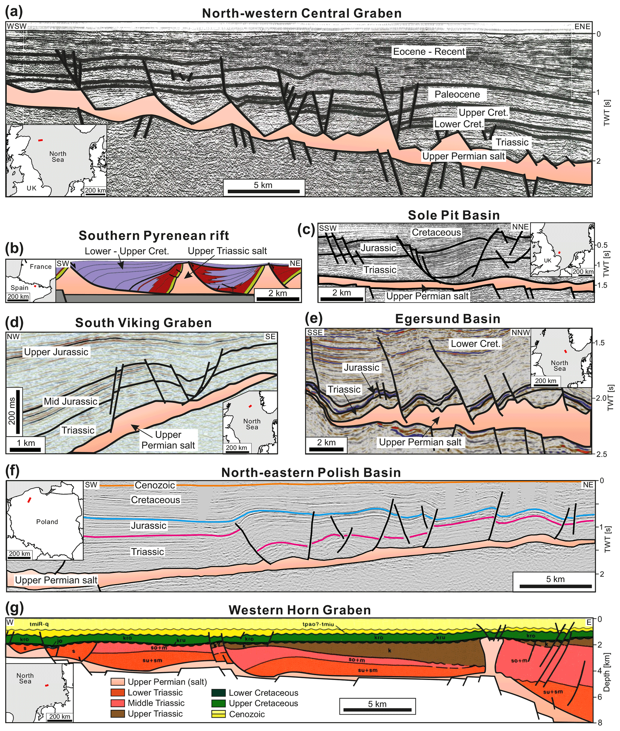
Figure 12Examples of thin-skinned extensional structures recognized above inclined flanks at the margins of salt-bearing rift basins. (a) North-western Central Graben (central North Sea): evenly spaced listric growth faults above a gently dipping, faulted sub-salt base (modified from Bishop, 1996). (b) Pyrenean rift system (northern Spain): sketched cross section based on geological field data showing thin-skinned listric growth faults and reactive diapirs of Upper Triassic salt (modified from Lopez-Mir et al., 2014). (c) Sole Pit Basin (south-western North Sea): thin-skinned graben structure (“Dowsing Graben System”) above the Permian salt detachment was partly attributed to gravity gliding into the bowl-shaped basin centre (modified from Stewart et al., 1996). (d) South Viking Graben (northern North Sea): supra-salt fault zone at the margin of a tilted half graben (modified from Jackson and Larsen, 2009). (e) Egersund Basin (“Sele High Fault System”; central North Sea): supra-salt fault zones above a slightly faulted salt base (modified from Jackson and Lewis, 2016). (f) North-eastern Polish Basin: peripheral extensional fault zones characterized by several supra-salt, tilted blocks and listric faults with increased thickness of Jurassic sediments. During the Late Cretaceous, the structure was inverted, and this inversion tectonic was associated with thin-skinned reverse faulting and folding (modified from Krzywiec, 2006b, 2012). (g) Horn Graben (south-eastern North Sea): listric growth faults in the Triassic strata overlie a relatively flat sub-salt base and are detached from the major graben structure (modified from Baldschuhn et al., 2001).
In the experiment with syn-kinematic sedimentation (ETSv), amounts of strain and displacement were considerably less than in the equivalent experiment without sedimentation (ETv) (Fig. 11c and d). No shortening took place in the graben centre in ETSv. In contrast, gravity gliding was accommodated by reduced extension at the graben edges and by diffuse shortening above the downslope flanks (Fig. 8d and f). This demonstrates that the ability of downward gliding is significantly reduced by sediment accumulation in the basin centre. Such a dynamic resistance is suggested to act in passive margin salt basins as well, where the gravity potential has to be large enough to overcome the strength of the downslope overburden in order to induce downward gliding and spreading (Gemmer et al., 2004; Rowan et al., 2004). After basal extension and flank tilting was stopped in ETSv, gravity-driven deformation decreased rapidly. In natural rift basins, however, thermal subsidence and flank tilting continues after rifting ceased such that gravity potential is further increased and gliding might last longer.
In ETSv, extensional strain at the basin margins and the graben edges occurred at one to two discrete fault zones, whereas it was distributed over several branched fault zones in ETv (without sedimentation) (Fig. 11c and d). This implies that sedimentary loading localizes the strain and causes subsidence in discrete extensional fault zones, whereas the initiation of new extensional zones is suppressed. Similar effects of syn-kinematic sedimentation on the strain patterns has been observed in analogue models of rift evolution (Zwaan et al., 2018) and passive margin salt basins (Ge et al., 2019a). In passive margin basins, syn-kinematic sedimentation during gravity gliding initially leads to symmetrical graben structures, which progressively transform into listric growth faults (e.g. Mauduit et al., 1997; Krézsek et al., 2007). Such structures also developed at the tilted basin margins in ETSv (Fig. 10) and, therefore, represent clear indicators of gravity gliding in SBRBs.
Experiment ETv (without sedimentation) and ETSv (including sedimentation) might represent end-member types of SBRBs of an underfilled basin (low sedimentation rates) and filled up basin (high sedimentation rates). Gravity gliding is favoured in underfilled rift basins or basins experiencing fast flank tilting relative to sedimentation rates. In such a case, the kinematic evolution and structural patterns are similar to passive margin basins in which basin tilting is the main driving factor for salt tectonics (e.g. Mauduit et al., 1997; Fort et al., 2004; Brun and Fort, 2011; Adam et al., 2012; Ge et al., 2019a, b). High sediment accumulation rates, in contrast, might effectively prevent gravity gliding which suggests that gravity gliding is not a compelling process in SBRBs with tilted flanks, i.e. with a noticeable gravity potential. This is a major difference to passive margin basins, where fast sediment supply from the continent accelerates salt tectonic processes as it has been shown by numerous analogue modelling studies (e.g. Ge et al., 1997; Mauduit et al., 1997; McClay et al., 2003; Vendeville, 2005; Krézsek et al., 2007; Brun and Fort, 2011). However, the exact conditions under which gravity gliding is completely blocked or still possible in SBRBs have not been investigated in our study and require a more comprehensive parameter study in which various ratios of sedimentation vs. tilting rates are tested.
5.2 Limitations of the apparatus and the procedure
In our experimental setup, basal extension is focused on two parallel faults, which is a simplification of a natural rift basin. Natural rift basins and the process of crustal extension include greater complexities than presented in our experimental setup. Rift basins usually consist of overlapping fault systems with normal faults, fault intersection, ramps, strike-slip segments, and intrabasinal ridges (e.g. Fazlikhani et al., 2017). Such diverse fault patterns in the sub-salt basement determine the distribution of the original salt, its post-depositional redistribution, and localization of salt structures (e.g. Koyi et al., 1993; Dooley et al., 2005; Dooley and Hudec, 2020). Similarly, the flanks in our model setup have an even base, whereas in nature the sub-salt base is often perturbed by an irregular relief resulting from, for instance, fault steps and volcanic edifices (e.g. Dooley et al., 2017; Ferrer et al., 2017). Basal discontinuities influence the strain localization in the viscous and brittle layers mainly because of abrupt changes in the thickness of the viscous layer (Gaullier et al., 1993; Dooley et al., 2017; Ferrer et al., 2017; Pichel et al., 2020) so that basin-margin extension zones are distributed above such basal steps rather then at the marginal pinch-out of the viscous layer.
Natural rift basins often possess asymmetrical half graben shapes characterized by a large-offset normal fault on one side and a smoothly tilted, slightly faulted flank on the other. In such half grabens, decoupled extension, probably caused by gravity gliding, can occur above the slightly tilted flank (e.g. Coward and Stewart, 1995; Thomas and Coward, 1996; Dooley et al., 2003; Jackson and Larsen, 2009; Ge et al., 2017; Lymer et al., 2018; Roma et al., 2018). Such alternative basin shapes have not been modelled in this study. Our experimental approach is to initially simplify the geometrical boundary conditions, and in a later experimental study further complexities can then be introduced; for example, such as static structural discontinuities can be inserted in the sub-silicone base to examine lateral variation in the strain patterns depending on initial thickness of the viscous layer.
A technical issue can be observed in Fig. 6g and h showing the incremental lateral movement of the flanks. Especially at the beginning of the extensional phase, this movement is not fully continuous and symmetrical on both sides, which likely results from mechanical locking of the graben block on the basal faults. This effect cannot be avoided even by using lubricants on the faults. Finally, the cumulative displacement of the extensional movement over longer time periods is smooth and regular as seen in Fig. 3e and f.
Boundary effects were observed along the sidewalls of the silicone basin in all experiments containing a viscous layer. En échelon shear patterns occurred close to the long edges of the silicone basin above the graben flanks (Fig. 7d). Furthermore, graben-edge fault zones are curved adjacent to the sidewalls (Fig. 7a and c). These features result from drag forces reducing silicone movement at the long basin edges. However, the fault zones in the centre of the basin are relatively straight and parallel (Fig. 7a–d). Thus, we suggest that the influence of the boundary effects on the strain and displacement patterns is negligible.
5.3 Application to nature and outlook
In many SBRBs worldwide (Table 1), the basin floor at the flanks is inclined and thin-skinned extensional faults occur in the supra-salt cover at the basin margins. The seismic examples shown in Fig. 12 resemble the basin-margin extensional fault zones observed in our experimental cross sections of experiment ETSv (Fig. 10). In our study such structures only occurred in experiments applying tilting. Thus, it can be proposed that these natural examples were also formed partly by gravity-driven extension. If so, our experimental results suggest that the initiation of these basin-edge fault zones was delayed from the initial post-salt rifting phase and that they might have remained active after rifting ceased. Such temporal relationships have to be evaluated in detail by cross section balancing for specific rift basins.
One of the most prominent examples of overlapping gravitationally and tectonically driven supra-salt extension can be found at the flanks of the northern Central Graben (central North Sea) (Fig. 1b). Rollover structures and separated overburden blocks (rafts) developed above the tilted outer platforms of the graben (Fig. 12a) contemporaneously with compressional structures, such as salt anticlines and squeezed diapirs, in and near the graben centre (Gibbs, 1984; Hodgson et al., 1992; Bishop et al., 1995; Buchanan et al., 1996; Penge et al., 1999; Stewart and Clark, 1999; Stewart, 2007). It is suggested that major gravity-driven salt movement coincided with the main period of rifting during Jurassic to Early Cretaceous times (Bishop et al., 1995; Buchanan et al., 1996; Stewart and Clark, 1999). However, it has also been postulated that gravity gliding affected the post-salt depositional patterns already during the Late Triassic initial rifting phase (Penge et al., 1999). In the Pyrenean rift system and the Basque–Cantabrian basin (North Iberian Margin), Early to Late Cretaceous “hyperextension” caused gravity-driven extension of the cover of the Late Triassic evaporites (López-Mir et al., 2015; Saura et al., 2016; Teixell et al., 2016; Lagabrielle et al., 2020). Rollovers and listric growth faults are documented in outcrops and seismic data (Fig. 12b) and indicate large-offset, thin-skinned extension at the southern basin margin (McClay et al., 2004; Jammes et al., 2010; Lopez-Mir et al., 2014; Saura et al., 2016; Labaume and Teixell, 2020). It is suggested that in the basin centre previously formed passive diapirs and the supra-salt cover were folded and overthrusted partly accommodating upslope extension (López-Mir et al., 2015; Labaume and Teixell, 2020). The amount of tectonic stretching and subsidence were relatively large in these two examples – the Iberian margin translated into early stage passive margins after mobilization of the salt. This likely resulted in steep slopes of the basin floor and a basin centre underfilled by sediments, which promoted gravity gliding. Hence, the style of salt tectonics in these basins was similar to that in many passive margin salt basins and as observed in our experiment ETv (Fig. 6d and f).
The Sole Pit and Silverpit basins (south-western North Sea) are confined by extensional fault zones, which overlie a slightly faulted salt base (Fig. 12c) (e.g. Hughes and Davison, 1993; Allen et al., 1994; Coward and Stewart, 1995; Griffiths et al., 1995; Stewart and Coward, 1995; Stewart et al., 1996). These extensional structures simultaneously developed with compressive buckle folds in the basin centre during the Early Triassic–Jurassic rifting. Observed supra-salt extensional displacement is larger than that of the sub-salt faults at the basin margins and, therefore, can be related to syn-rift gravity gliding (e.g. Jenyon, 1985; Allen et al., 1994; Coward and Stewart, 1995; Griffiths et al., 1995; Stewart et al., 1996). Similar relationships between thin-skinned extension at basin margins and buckle folding and salt pillow growth further downslope are documented in the western (e.g. Thieme and Rockenbauch, 2001; Mohr et al., 2005; Vackiner et al., 2013) and the north-eastern part of the North German Basin (Ahlrichs et al., 2020). The examples show that gravity gliding can also occur in less extended rift basins, whereas the amount of gravity-driven extension is minor as well.
The south Viking Graben and the Egersund Basin (northern North Sea) are salt-bearing half grabens in which the hanging wall graben centre was rotated during rifting (Geil, 1991; Thomas and Coward, 1996; Jackson and Larsen, 2009; Tvedt et al., 2013; Stewart, 2014; Jackson and Lewis, 2016). At the upslope edges of the rotated grabens, thin-skinned extensional growth faults (Fig. 12d and e) are supposed to be triggered by gravity gliding (Jackson and Larsen, 2009; Tvedt et al., 2013; Jackson and Lewis, 2016). In the south Viking Graben, thin-skinned extension was initiated at a tilting angle of < 2∘ and slightly delayed from the Middle Jurassic main rifting phase. At the edge of the Egersund Basin (Sele High), gravity-driven supra-salt extension occurred during the Early Cretaceous and, therefore, also delayed from the Late Jurassic rifting (Jackson and Lewis, 2016). These observations of the timing of gravity gliding are supported by our experiments (ETv, Fig. 6d and f; ETSv, Fig. 8) in which gravity gliding started later than and continued after the basal extension.
Extensional fault zones developed above gently dipping flanks of the Polish Basin from the Late Triassic to Jurassic, in particular along the NE flank located above the East European Craton (Fig. 12f) (Krzywiec, 2006a, 2012). In this basin, however, reactive diapirs and deeply subsided minibasins evolved in the basin centre so that it is difficult to evaluate the effects of gravity gliding. We can only speculate that the basin-margin extension was balanced by reduced supra-salt extension in the basin centre as it was observed in experiment ETSv (Fig. 8).
Listric growth faults developed in the post-salt strata on the western flank of the Horn Graben (southern North Sea) (Fig. 12g) (Best et al., 1983; Baldschuhn et al., 2001). However, the underlying sub-salt base is only slightly inclined and faulted. Thus, it is suggested that supra-salt fault zones are rather detached from large-offset sub-salt normal faults in the nearby graben structure and purely tectonically driven (Nalpas and Brun, 1993; Stewart and Coward, 1996). This example demonstrates that there are structural similarities between tectonically and gravitationally driven thin-skinned fault zones underlining the necessity to find distinct structural and kinematic characteristics of both drivers.
These examples imply that there are three different scenarios of the interaction between gravity gliding and crustal extension: (1) gravity gliding took place during the main phase of rifting but no or minor shortening occurred in the basin centre, since here sub-salt extension was sufficient to accommodate and balance upslope, supra-salt extension (probably in the northern Central Graben); (2) gravity gliding is superimposed with minor rifting and caused basin-margin extension balanced by basin-centre shortening (e.g. in the Sole Pit Basin); and (3) no or only minor gravity gliding occurred, and the thin-skinned extensional structures were mainly tectonically driven (e.g. in the Horn Graben). In order to investigate these scenarios and their governing parameters and processes, we intend to perform a comprehensive analogue modelling study, modifying variables such as extension rate, tilting rate, layer thickness, and timing of tilting in relation to extension.
Our new experimental apparatus successfully reproduced the overlapping influence of tectonic extension and gravity gliding on salt flow and salt structure evolution in salt-bearing rift basins. The apparatus is suitable for simulating crustal extension within a symmetric graben structure and thermal subsidence, which is represented by vertical uplift of the graben flanks. Since basal extension and flank tilting can be controlled separately, the effects of both processes can be investigated separately or combined.
The preliminary experimental study shown here reveals primary structural and kinematic differences depending on the presence of a viscous layer in the sedimentary strata and the occurrence of flank tilting in rift basins. Whereas deformation in the brittle-only experiments is strictly coupled to the movement of the basal parts, widespread lateral displacement and distributed faulting affected the cover in brittle–viscous experiments.
In the brittle–viscous experiment in which only basal extension was applied, deformation is concentrated in regions close to the basal graben structure. Extensional fault zones develop in the footwall, while overburden above the basal normal faults slides into the graben. When the graben flanks become tilted simultaneously to graben extension, similar deformation patterns occur close to the graben. However, they are overprinted by gravity gliding inducing widespread basin-wide downward movement of the overburden into the central graben. Consequently, additional extension localizes at the upslope basin margins, which is enhanced after basal extension and tilting have stopped. This extension is accommodated in the graben region by reduced amounts of extension on the graben-edge fault zones and compressional strain above the graben bounding faults. If syn-kinematic sedimentation is included in the experimental procedure, lateral downward-directed displacement is significantly reduced especially during the post-extensional phase. Furthermore, strain in the margin-edge extensional zones is localized on fewer, more discrete faults.
Observed basin-margin extensional structures in the preliminary experiments resemble typical thin-skinned extensional structures occurring at the flanks of many salt-bearing rift basins with inclined sub-salt bases. Such diagnostic structures indicate that gravity gliding might play an important role in the post-salt structural development of such rift basins.
For the analogue model to be representative of the natural prototype, models have to be geometrically, dynamically, kinematically, and rheologically similar to their natural prototype (Hubbert, 1937; Weijermars et al., 1993). In the presented models, we simulated the deformation processes of tectonically driven extension and gravity-driven gliding and spreading and identified the following characteristic parameters describing the boundary conditions of these processes (cf. Fig. B1): layer thickness (hb, hv), densities (ρb, ρv), cohesion and the coefficient of internal friction of the brittle overburden (C, μ), viscosity of the substratum (η), extension rate (ve), and tilting rate (vt). In order to relate these parameters between nature and the model, we applied standard scaling procedures as in other studies about geological systems consisting of viscous substratum and brittle cover (Hubbert, 1937; Ramberg, 1981; Weijermars and Schmeling, 1986; Davy and Cobbold, 1991; Weijermars et al., 1993; Bonini et al., 2012).
Geometric scaling ensures that corresponding ratios of lengths and angles are comparable between the model and nature. The choice of the geometrical scaling ratio is determined by the procedure for dynamical scaling (Pollard et al., 2005) and, in our study, similar to previous model studies (e.g. Vendeville et al., 1995; Koyi et al., 1993; Warsitzka et al., 2015; Dooley and Hudec, 2020):
This means that 1 cm in the model represents 1 km in nature, and characteristic geometrical relationships, such as the thickness ratio between overburden and salt or the ratio between extensional displacement and flank uplift, can be scaled accordingly (Table 1).
Fundamental principles of dynamical scaling require that trajectories and ratios of forces acting on the material have to be equal and that rheological behaviours of the involved materials are similar (Weijermars and Schmeling, 1986; Pollard et al., 2005). This can be translated into the concept that driving and resisting forces of the relevant processes have to be related properly. In salt tectonics, driving forces are produced by (1) vertical loading of sediments resulting in gravitational buoyancy forces and by (2) tectonic stresses resulting in lateral pressure forces (Jackson and Hudec, 2017). Resisting forces are caused by (1) the frictional strength of the brittle overburden (SF) and by (2) viscous stresses in the substratum (Sv) caused by drag at its boundaries (Jackson and Hudec, 2017). Inertial forces can be regarded as insignificant, since strain rates during solid rock flow are very low (Ramberg, 1981; Weijermars and Schmeling, 1986).
Because deformation style and localization in the materials is mostly influenced by rheological parameters of the viscous layer and its brittle overburden, a characteristic measure for dynamical scaling is the brittle-to-viscous strength ratio or brittle–viscous coupling (BVC) (e.g. Sornette et al., 1993; Schueller and Davy, 2008). This is calculated by integrating the differential stress over the layer thicknesses (Schueller and Davy, 2008):
The frictional strength of both brittle sediments and experimental granular materials obeys the Mohr–Coulomb criterion, according to which the mean stress σm and the maximum shear stress τmax are related by (Byerlee, 1978; Dahlen, 1990; Jaeger et al., 2007)
Here, ϕ is the angle of internal friction and C the cohesion. Translated into an expression by the maximum and the minimum principal stresses σ1 and σ3, this gives
In an extensional stress field, the maximal principal stress σ1 equals the lithostatic pressure σL:
where g is the gravitational acceleration and ρb the density of the brittle overburden. Furthermore, the minimal principal stress σ3 is horizontal:
With the presence of a pore fluid pressure, each pressure has to be corrected by the pore fluid pressure ratio (Hubbert–Rubey coefficient of fluid pressure λ) (Weijermars et al., 1993):
Assuming that pore fluid pressure is hydrostatic, λ becomes roughly 0.45 for an average overburden density of 2200 kg m−3 and a fluid density of 1050 kg m−3. The critical horizontal stress at failure (Dahlen, 1990)
Combining Eqs. (A4), (A5), and (A8) gives the brittle strength in a tensional stress regime (Weijermars et al., 1993):
The force required for extensional failure is then derived by integrating SF over the thickness hb (Schueller and Davy, 2008):
The large-scale viscous behaviour of a salt layer is characterized by a stress–strain rate relationship. Rock salt (halite), which usually constitutes the main volumetric proportion of a mobilized evaporitic succession (Jackson and Hudec, 2017), deforms by a combination of dislocation and diffusion (solution–precipitation) creep mechanisms depending on grain size, temperature, strain rate, percentage of intercrystalline fluids, and confining pressure (e.g. Schléder et al., 2008; Urai et al., 2008). The large-scale deformation behaviour is suggested to be an average of these creep laws (Weijermars and Schmeling, 1986). At relatively low strain rates (< ∼ 10−13 s−1), low confining pressure (< 106 Pa), grain sizes of < 1 cm, and a typical temperature range (20–200 ∘C), rock salt deformation is dominated by diffusion creep, which is characterized by a linear stress–strain rate relationship (Newtonian fluid) (Van Keken et al., 1993). At higher strain rates and confining pressure, the deformation is a combination of diffusion and dislocation creep so that the shear stress–strain rate relationship is logarithmic (power-law fluid) and salt shows a strain rate softening behaviour (Urai et al., 2008; Van Keken et al., 1993). Silicone putty, which is commonly used in salt tectonic experiments, possesses a strain rate softening behaviour for strain rates > 10−2 s−1 (Rudolf et al., 2016). However, such high strain rates are not reached in the presented models. Thus, for modelling purposes, the salt layer is here approximated as temperature-independent, mechanically uniform viscous material with a linear (Newtonian) stress–strain rate behaviour This condition might be true for wet salt (> ∼ 0.05 wt % water content) with relatively small grain sizes (< 0.5 mm) (Urai et al., 2008). Under this assumption, differential (viscous) stress is calculated by (Weijermars et al., 1993; Bonini et al., 2012; Turcotte and Schubert, 2014)
Here, η is the dynamic viscosity and the shear strain rate in x direction. Integrating Eq. (A11) over the thickness of the viscous layer hv gives the viscous force:
Tectonic extension induces a Couette shear flow (Turcotte and Schubert, 2014) at the base of the silicone on the flanks. Hence, can be approximated by the ratio of the shear velocity vx at the base of viscous layer and the thickness of the viscous layer hv so that Eq. (A12) becomes
For comparison between nature and the model, we inserted a range of possible natural and experimental values (Table B1) in Eqs. (A10) and (A13). To achieve correct dynamical scaling, BVC (Eq. A2) should be equal for the model and nature. However, accurate scaling is difficult to achieve because natural values of viscosity (1016–1019 Pa s; Van Keken et al., 1993; Mukherjee et al., 2010) and strain rates (10−16–10−14 s−1; Jackson and Hudec, 2017) can be highly variable so that FV can vary over several orders of magnitude (Table B1). Nevertheless, the curves in Fig. B2a show that BVC for the model and nature is relatively similar for a wide range of values.
Equation (A10) reveals that the thickness of the overburden hb mainly governs the coupling between brittle and viscous layer due to its quadratic input. Frictional forces are 1–2 orders of magnitude higher than viscous forces, at least at the beginning of the experiment when strain in the viscous layer is distributed widely. During progressive strain localization in later stage of the experiment, higher strain rates and, hence, higher viscous forces arise.
The ratio between brittle and viscous material properties also sets the scaling for the strain rates allowing us to relate extension, tilting, and sedimentation rates between the model and nature (Weijermars et al., 1993; Allen and Beaumont, 2012). Accordingly, the velocity scaling ratio can be calculated by the viscosity of the substratum, the normal stress, and the characteristic length, e.g. the thickness hb (Weijermars et al., 1993; Allen and Beaumont, 2012):
Applying average values of viscosity, thickness, and density (Table B1), the velocity scaling ratio is ∼ 104. Natural extension rates vary between 0.1 and 10 mm a−1. Hence, experimental extension rates should be in the range of ∼ 0.1 to 10 mm h−1. We choose an intermediate rate of 1 mm h−1 for practical reasons.
Tectonic stresses and gravity are the main driving factors in the geological scenarios modelled here. For scaling purposes we used the Argand number (Ar) (e.g. England and McKenzie, 1982; Schueller and Davy, 2008), which relates tectonic forces to the buoyancy force FB. The tectonic force is approximated by the integrated strength of the brittle and the viscous layer and, therefore, the sum of FF (Eq. A10) and FV (Eq. A13). Thus, the Argand number is calculated by
The buoyancy force FB results from isostatic sinking of the overburden into the viscous substratum, which is calculated by the weight of the overburden depending on thickness and density and the weight of the equivalent volume of the viscous substratum (e.g. Zoback and Mooney, 2003; Schueller and Davy, 2008):
where Δhv is the amount of subsidence of the overburden into the viscous layer. Under isostatic conditions, Δhv is
After integration, Eq. (A16) becomes
FB is mainly influenced by the density ratio between overburden (ρb) and salt (ρv). Salt density is constant with depth, whereas the density of other sediments increases with depth due to compaction (see Appendix B). During the early stage of the basin history, the overburden density ρb is smaller than the salt density ρb so that FB is negative. It changes to positive values when ρb exceeds ρv.
When inserting a range of possible values (Table B1) into Eq. (A15), the curve shapes of Ar (Fig. B2b) are similar between the model and nature. Ar changes from negative to positive values, meaning the general behaviour of the influence of buoyancy force is adequately approximated in the models.
The average density of a salt layer is nearly constant with depth (∼ 2150 kg m−3). In contrast, sedimentary rocks consolidate during burial (Fig. B3a and b). Due to chemical mineralization and mechanical compaction the porosity ϕ of these sediments decreases with depth leading to an increasing density. The most common porosity–depth relationship is given by Athy's law (Athy, 1930):
where ϕ0 and c stand for the initial porosity and the depth coefficient. The corresponding density ρb(z) at each depth can then be calculated by using the grain density ρG (Fig. B3b) and the density of the pore fluid ρF:
Integrating over the entire thickness of the cover hb gives the average density of the cover:
Because of this density increase, the bulk density of overburden sediments is smaller than that of salt at shallow depths and exceeds the average salt density at a depth between 2200 and 3800 m (e.g. Jackson and Talbot, 1986; Hudec et al., 2009) (Fig. B3b). Exceeding this thickness, the overburden is able to autonomously subside into the salt layer and squeeze the salt upwards (Warsitzka et al., 2018).
Compaction of natural sediments cannot be directly simulated in analogue models using the common granular materials. However, it is not the density increase itself, but the increase in the lithostatic pressure at the base of the overburden that is the crucial parameter determining differential loading and the pressure gradient in the viscous layer. In order to simulate an appropriately scaled increase in the lithostatic pressure, we increased the density of the sand mixture (ρbmi) during each step of syn-kinematic sand accumulation, similar to the approach by Dooley and Hudec (2020). This results in an inverse density stratification with less dense material at the bottom and denser material at the top of the cover (Fig. B3c) and a stepwise increase in the bulk density of the entire sand cover. To compare natural with experimental density–depth curves, the standardized density ρ′ was calculated by dividing all density values through the density of the salt or the silicone, respectively. Likewise, the depth was standardized by dividing the depth through the maximal thickness of the cover (here: 5 cm in the model and 5 km in nature).
The increase in density of each new sand layer has to be set in such a manner that the standardized bulk density resembles the exponential increase in the standardized bulk density in nature (Fig. B3d). During the experiment, we first estimated the maximum thickness of the next syn-kinematic sand layer, which roughly equals the amount of vertical subsidence of the central graben block. Then, the standardized density of this layer, which depends on the total thickness of the sand column in the graben centre, is given by the correlation shown in Fig. B3d. Based on that, the bulk density of the next syn-kinematic layer can be calculated and the appropriate mixture of quartz sand and silicate cenospheres can be produced. In advance, we determined bulk densities of various mixing ratios. The ratios in experiment ETSv ranged from 3:8 to 3:2 (quartz sand : silicate cenospheres in volumetric fractions), which produced bulk densities of 850 to 1160 kg m−3.
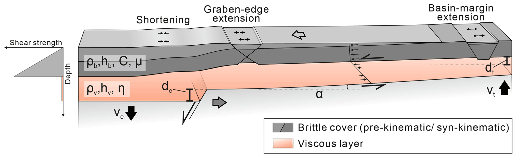
Figure B1Physical parameters describing the deformation processes in the experiments. Lateral displacement due to basal extension and downward gliding of the overburden lead to shearing at the base and the top of viscous layer. Vertical displacement of the graben block and the flanks cause gravitational instability in the viscous layer. Syn-kinematic sedimentation, i.e. filling the subsided depocentres, imposes differential loading on top of the viscous layer. Governing parameters describing these processes are as follows: α – tilt angle of the basin flank; de – vertical displacement of the graben centre; dt – vertical displacement of the graben flanks; hb – thickness of the brittle overburden; hv – thickness of the viscous substratum; η – dynamic viscosity; μ – coefficient of internal friction; C – cohesion; ρb – density of the brittle overburden; ρv – density of the viscous substratum; ve – (vertical) extension rate; vt – tilting rate.
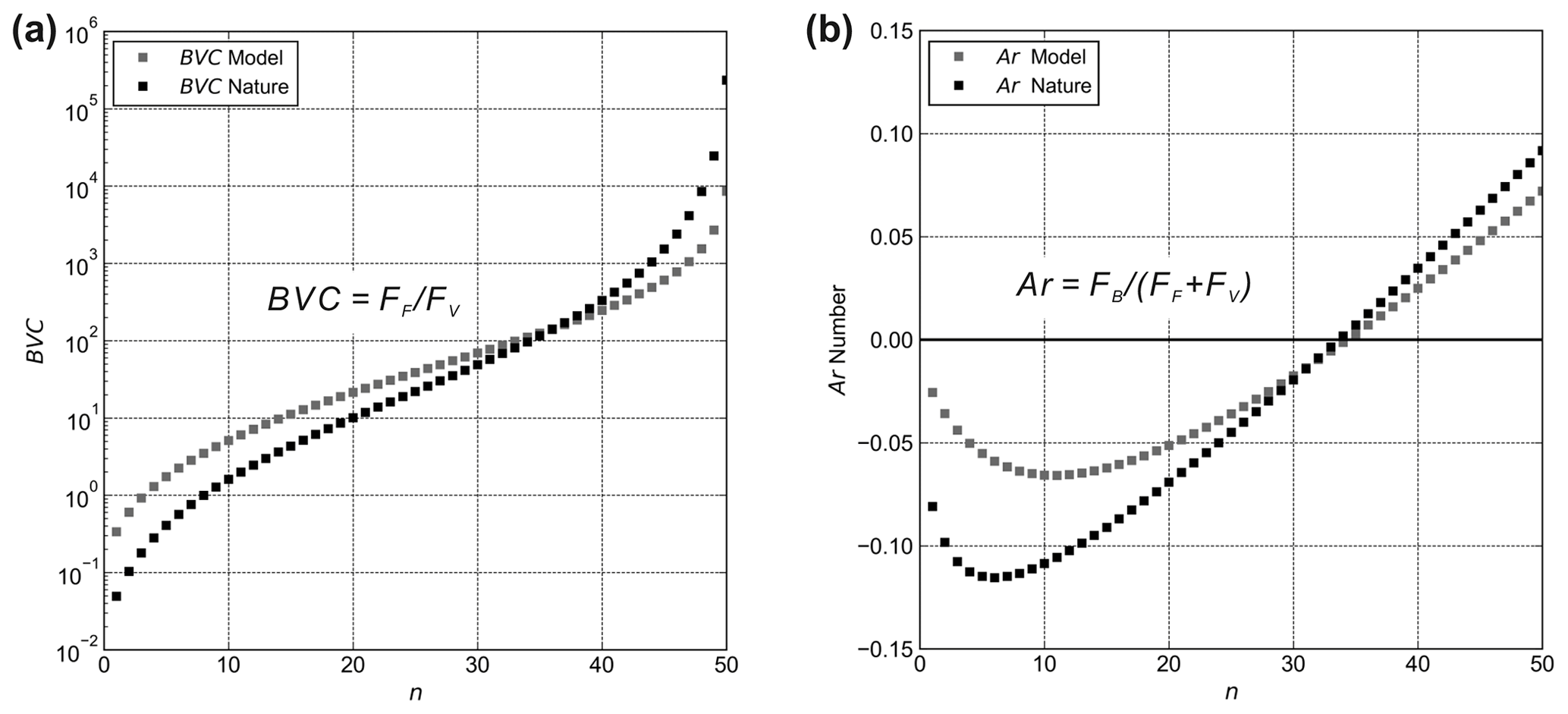
Figure B2Diagrams of the (a) brittle–viscous coupling (BVC) and (b) the Argand number (Ar) for natural and experimental values. To calculate the values of both parameters, arrays of each input parameter were inserted in Eqs. (A2) and (A15). For each parameter, the array contains 50 equidistant values ranging between the minimum and maximum values given in Table B1. Ar – Argand number; BVC – brittle–viscous coupling; FB – buoyancy force; FF – frictional force in the brittle layer; FV – viscous force in the substratum.

Figure B3Density configuration in the natural prototype and in the analogue model. (a) Natural sediments compact during burial leading to an increasing density ρbn with depth according to Athy's law (Athy, 1930). (b) Curves of the bulk density for different sediment types related to the thickness of the overburden. The blue curve shows the bulk density calculated by using average (avg) values listed in the table. (c) Inverse density stratification in the analogue model. Layers with increased density are sieved in leading to an increasing bulk density during subsidence. (d) Standardized (Std.) thickness and density values for nature and the model. Thickness was standardized by the (presumed) maximum thickness of the overburden (nature: 5 km; model: 5 cm). Density values were standardized by dividing the density of the cover (nature: ρbn; model: ρbm) by the density of the viscous layer (nature: ρvn; model: ρvm). Note that the density of each sieved layer in the models increases upwards. This procedure is applied to increase the bulk density of the subsiding overburden in a similar manner as in nature. ϕ0 – initial porosity; c – depth coefficient; ρG – grain density.
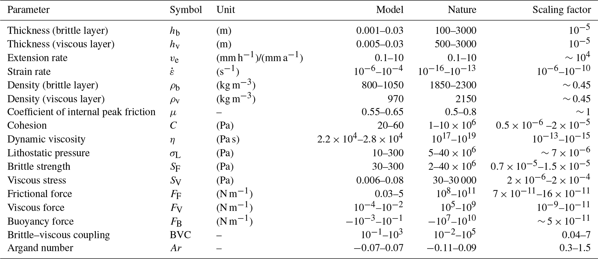
Data of the experiments presented here are provided in a data publication via the PANGAEA Data Publisher for Earth & Environmental Science (Warsitzka et al., 2021a) (https://doi.org/10.1594/PANGAEA.931848).
MW invented the concept of this modelling study, designed the experimental apparatus, performed the experiments, and composed the main parts of the paper. Furthermore, data processing and analysis was undertaken by MW. PZ advised the designing and construction of the apparatus and assisted during the experiments. Theoretical input for planing the project, the model design and the concept of the experiments came from FJK. PK supported the comparison of the experiments with the natural case study of the Polish Basin. FJK, PK, and PZ helped with finalizing the paper.
The authors declare that they have no conflict of interest.
Publisher’s note: Copernicus Publications remains neutral with regard to jurisdictional claims in published maps and institutional affiliations.
This paper was prepared as part of a bilateral research project between the Institute of Geophysics of the Czech Academy of Sciences and the Institute of Geological Sciences of the Polish Academy of Sciences (project no.: PAN-20-04). We acknowledge Oriol Ferrer, Gaëël Lymer, and Frank Zwaan for providing constructive and valuable reviews, which significantly improved the paper. Graham Hill is thanked for remarks on an early version of the paper. We thank Jiří Semerád for helping with designing and for constructing the experimental apparatus. We also thank GFZ Data Services for providing an openly accessible publication of data related to this study (Warsitzka et al., 2021b).
The research position of Michael Warsitzka is supported by the Czech Academy of Science (AVCR) in the framework of the “Programme to support prospective human resources – post Ph.D. candidates” (no.: L100121901)
This paper was edited by Susanne Buiter and reviewed by Oriol Ferrer, Gaël Lymer, and Frank Zwaan.
Adam, J., Urai, J. L., Wieneke, B., Oncken, O., Pfeiffer, K., Kukowski, N., Lohrmann, J., Hoth, S., Van der Zee, W., and Schmatz, J.: Shear localisation and strain distribution during tectonic faulting – new insights from granular-flow experiments and high-resolution optical image correlation techniques, J. Struct. Geol., 27, 283–301, https://doi.org/10.1016/j.jsg.2004.08.008, 2005. a, b, c
Adam, J., Ge, Z., and Sanchez, M.: Post-rift salt tectonic evolution and key control factors of the Jequitinhonha deepwater fold belt, central Brazil passive margin: Insights from scaled physical experiments, Mar. Pet. Geol., 37, 70–100, https://doi.org/10.1016/j.marpetgeo.2012.06.008, 2012. a
Ahlrichs, N., Hübscher, C., Noack, V., Schnabel, M., Damm, V., and Krawczyk, C. M.: Structural evolution at the northeast North German Basin margin: From initial Triassic salt movement to Late Cretaceous-Cenozoic remobilization, Tectonics, 39, e2019TC005927, https://doi.org/10.1029/2019TC005927, 2020. a
Allen, J. and Beaumont, C.: Impact of inconsistent density scaling on physical analogue models of continental margin scale salt tectonics, J. Geophys. Res.-Sol. Ea., 117, B08103, https://doi.org/10.1029/2012JB009227, 2012. a, b
Allen, M. R., Griffiths, P. A., Craig, J., Fitches, W. R., and Whittington, R. J.: Halokinetic initiation of Mesozoic tectonics in the southern North Sea: a regional model, Geol. Mag., 131, 559–561, https://doi.org/10.1017/S0016756800012164, 1994. a, b
Alves, T. M., Gawthorpe, R. L., Hunt, D. W., and Monteiro, J. H.: Jurassic tectono-sedimentary evolution of the Northern Lusitanian Basin (offshore Portugal), Mar. Pet. Geol., 19, 727–754, https://doi.org/10.1016/S0264-8172(02)00036-3, 2002. a
Athy, L. F.: Density, porosity, and compaction of sedimentary rocks, AAPG Bull., 14, 1–24, https://doi.org/10.1306/3D93289E-16B1-11D7-8645000102C1865D, 1930. a, b
Augustin, N., Devey, C. W., Van der Zwan, F. M., Feldens, P., Tominaga, M., Bantan, R. A., and Kwasnitschka, T.: The rifting to spreading transition in the Red Sea, Earth Planet. Sc. Lett., 395, 217–230, https://doi.org/10.1016/j.epsl.2014.03.047, 2014. a
Baldschuhn, R., Binot, F., Fleig, S., Kockel, F., (Hrsg.) unter Mitarbeit von: Best, G., Brückner-Röhling, S., Deneke, E., Frisch, U., Hoffmann, N., Jürgens, U., Krull, P., Röhling, H.-G., Schmitz, J., Sattler-Kosinowski, S., Stancu-Kristoff, G., and Zirngast, M.: Geotektonischer Atlas von Nordwest-Deutschland und dem deutschen Nordsee-Sektor, Strukturen, Strukturentwicklung, Paläogeographie, Geol. Jahrb., A, 153, 1–88, 3 CD–ROMs, 2001. a, b, c
Best, G.: Floßtektonik in Norddeutschland: Erste Ergebnisse reflexionsseismischer Untersuchungen an der Salzstruktur “Oberes Allertal”, Z. Dtsch. Geol. Ges., 147, 455–464, 1996. a
Best, G., Kockel, F., and Schöneich, H.: Geological history of the southern Horn Graben, Geol. Mijnbouw, 62, 25–33, 1983. a, b
Bishop, D. J.: Regional distribution and geometry of salt diapirs and supra-Zechstein Group faults in the western and central North Sea, Mar. Petrol. Geol., 13, 355–364, https://doi.org/10.1016/0264-8172(95)00081-X, 1996. a
Bishop, D. J., Buchanan, P. G., and Bishop, C. J.: Gravity-driven thin-skinned extension above Zechstein Group evaporites in the western central North Sea: an application of computer-aided section restoration techniques, Mar. Pet. Geol., 12, 115–135, https://doi.org/10.1016/0264-8172(95)92834-J, 1995. a, b
Bodego, A. and Agirrezabala, L. M.: Syn-depositional thin-and thick-skinned extensional tectonics in the mid-Cretaceous Lasarte sub-basin, western Pyrenees, Basin Res., 25, 594–612, https://doi.org/10.1111/bre.12017, 2013. a
Bonini, M., Sani, F., and Antonielli, B.: Basin inversion and contractional reactivation of inherited normal faults: A review based on previous and new experimental models, Tectonophysics, 522, 55–88, https://doi.org/10.1016/j.tecto.2011.11.014, 2012. a, b
Brun, J.-P. and Fort, X.: Compressional salt tectonics (Angolan margin), Tectonophysics, 382, 129–150, https://doi.org/10.1016/j.tecto.2003.11.014, 2004. a
Brun, J.-P. and Fort, X.: Salt tectonics at passive margins: Geology versus models, Mar. Pet. Geol., 28, 1123–1145, https://doi.org/10.1016/j.marpetgeo.2011.03.004, 2011. a, b, c, d, e
Brun, J.-P. and Mauduit, T. P.-O.: Salt rollers: structure and kinematics from analogue modelling, Mar. Pet. Geol., 26, 249–258, https://doi.org/10.1016/j.marpetgeo.2008.02.002, 2009. a
Buchanan, P. G., Bishop, D. J., and Hood, D. N.: Development of salt-related structures in the Central North Sea: results from section balancing, Geol. Soc. Lond., Spec. Pub., 100, 111–128, https://doi.org/10.1144/GSL.SP.1996.100.01.09, 1996. a, b, c, d, e
Burliga, S., Koyi, H. A., and Chemia, Z.: Analogue and numerical modelling of salt supply to a diapiric structure rising above an active basement fault, Geol. Soc. Lond., Spec. Pub., 363, 395–408, https://doi.org/10.1144/SP363.18, 2012. a
Byerlee, J.: Friction of rocks, Pure and applied geophysics, 116, 615–626, https://doi.org/10.1007/978-3-0348-7182-2_4, 1978. a
Cámara, P.: Inverted turtle salt anticlines in the eastern Basque-Cantabrian basin, Spain, Mar. Petrol. Geol., 117, 104358, https://doi.org/10.1016/j.marpetgeo.2020.104358, 2020. a
Chapman, T. J.: The Permian to Cretaceous structural evolution of the Western Approaches Basin (Melville sub-basin), UK, in: Inversion Tectonics, Geological Society of London, 44, 177–200 https://doi.org/10.1144/GSL.SP.1989.044.01.11, 1989. a
Clausen, O. R. and Pedersen, P. K.: Late Triassic structural evolution of the southern margin of the Ringkøbing-Fyn High, Denmark, Mar. Pet. Geol., 16, 653–665, https://doi.org/10.1016/S0264-8172(99)00026-4, 1999. a
Coleman, A. J., Jackson, C. A.-L., and Duffy, O. B.: Balancing sub-and supra-salt strain in salt-influenced rifts: Implications for extension estimates, J. Struct. Geol., 102, 208–225, https://doi.org/10.1016/j.jsg.2017.08.006, 2017. a
Coward, M. and Stewart, S.: Salt-Influenced Structures in the Mesozoic-Tertiary Cover of the Southern North Sea, UK, in: Salt tectonics: a global perspective, edited by: Jackson, M. P. A., Roberts, D. G., and Snelson, S., AAPG Mem., 65, 229–250, 1995. a, b, c, d
Dadlez, R., Narkiewicz, M., Stephenson, R. A., Visser, M. T. M., and Van Wees, J. D.: Tectonic evolution of the Mid-Polish Trough: modelling implications and significance for central European geology, Tectonophysics, 252, 179–195, https://doi.org/10.1016/0040-1951(95)00104-2, 1995. a
Dahlen, F. A.: Critical taper model of fold-and-thrust belts and accretionary wedges, Annu. Rev. Earth Planet. Sci., 18, 55–99, https://doi.org/10.1146/annurev.ea.18.050190.000415, 1990. a, b
Dancer, P. N., Algar, S. T., and Wilson, I. R.: Structural evolution of the Slyne Trough, in: Petroleum Geology of Northwest Europe: Proceedings of the 5th Conference, Geological Society, London, 5, 445–453, https://doi.org/10.1144/0050445, 1999. a
Davy, P. and Cobbold, P. R.: Experiments on shortening of a 4-layer model of the continental lithosphere, Tectonophysics, 188, 1–25, 1991. a, b
Dooley, T. P. and Hudec, M. R.: Extension and inversion of salt-bearing rift systems, Solid Earth, 11, 1187–1204, https://doi.org/10.5194/se-11-1187-2020, 2020. a, b, c, d, e
Dooley, T. P., McClay, K. R., and Pascoe, R.: 3D analogue models of variable displacement extensional faults: applications to the Revfallet Fault system, offshore mid-Norway, Geol. Soc. Lond., Spec. Pub., 212, 151–167, https://doi.org/10.1144/GSL.SP.2003.212.01.10, 2003. a, b
Dooley, T. P., McClay, K. R., Hempton, M., and Smit, D.: Salt tectonics above complex basement extensional fault systems: results from analogue modelling, in: Geological Society, London, Petroleum Geology Conference series, Geological Society of London, 6, 1631–1648, https://doi.org/10.1144/0061631, 2005. a, b, c, d, e
Dooley, T. P., Hudec, M. R., Carruthers, D., Jackson, M. P. A., and Luo, G.: The effects of base-salt relief on salt flow and suprasalt deformation patterns–Part 1: Flow across simple steps in the base of salt, Interpretation, 5, 1–23, https://doi.org/10.1190/INT-2016-0087.1, 2017. a, b, c
Duffy, O. B., Gawthorpe, R. L., Docherty, M., and Brocklehurst, S. H.: Mobile evaporite controls on the structural style and evolution of rift basins: Danish Central Graben, North Sea, Basin Res., 25, 310–330, https://doi.org/10.1111/bre.12000, 2013. a
England, P. and McKenzie, D.: A thin viscous sheet model for continental deformation, Geophys. J. Int., 70, 295–321, https://doi.org/10.1111/j.1365-246X.1982.tb04969.x, 1982. a
Fazlikhani, H., Fossen, H., Gawthorpe, R. L., Faleide, J. I., and Bell, R. E.: Basement structure and its influence on the structural configuration of the northern North Sea rift, Tectonics, 36, 1151–1177, https://doi.org/10.1002/2017TC004514, 2017. a
Ferrer, O., Roca, E., Benjumea, B., Muñoz, J. A., Ellouz, N., and Marconi Team: The deep seismic reflection MARCONI-3 profile: Role of extensional Mesozoic structure during the Pyrenean contractional deformation at the eastern part of the Bay of Biscay, Mar. Petrol. Geol., 25, 714–730, https://doi.org/10.1016/j.marpetgeo.2008.06.002, 2008. a
Ferrer, O., Jackson, M. P. A., Roca, E., and Rubinat, M.: Evolution of salt structures during extension and inversion of the Offshore Parentis Basin (Eastern Bay of Biscay), Geol. Soc. Lond., Spec. Pub., 363, 361–380, https://doi.org/10.1144/SP363.16, 2012. a
Ferrer, O., Roca, E., and Vendeville, B.: The role of salt layers in the hangingwall deformation of kinked-planar extensional faults: Insights from 3D analogue models and comparison with the Parentis Basin, Tectonophysics, 636, 338–350, https://doi.org/10.1016/j.tecto.2014.09.013, 2014. a, b
Ferrer, O., Gratacós, O., Roca, E., and Muñoz, J. A.: Modeling the interaction between presalt seamounts and gravitational failure in salt-bearing passive margins: The Messinian case in the northwestern Mediterranean Basin, Interpretation, 5, 99–117, https://doi.org/10.1190/INT-2016-0096.1, 2017. a, b
Fort, X., Brun, J.-P., and Chauvel, F.: Salt tectonics on the Angolan margin, synsedimentary deformation processes, AAPG Bull., 88, 1523–1544, https://doi.org/10.1306/06010403012, 2004. a, b, c, d
Gaullier, V., Brun, J. P., Gue, G., and Lecanu, H.: Raft tectonics: the effects of residual topography below a salt décollement, Tectonophysics, 228, 363–381, https://doi.org/10.1016/0040-1951(93)90349-O, 1993. a
Ge, H., Jackson, M. P. A., and Vendeville, B. C.: Kinematics and dynamics of salt tectonics driven by progradation, AAPG Bull., 81, 398–423, https://doi.org/10.1306/522B4361-1727-11D7-8645000102C1865D, 1997. a, b, c
Ge, Z., Gawthorpe, R. L., Rotevatn, A., and Thomas, M. B.: Impact of normal faulting and pre-rift salt tectonics on the structural style of salt-influenced rifts: The Late Jurassic Norwegian Central Graben, North Sea, Basin Res., 29, 674–698, https://doi.org/10.1111/bre.12219, 2017. a, b, c
Ge, Z., Rosenau, M., Warsitzka, M., and Gawthorpe, R. L.: Overprinting translational domains in passive margin salt basins: insights from analogue modelling, Solid Earth, 10, 1283–1300, https://doi.org/10.5194/se-10-1283-2019, 2019a. a, b
Ge, Z., Warsitzka, M., Rosenau, M., and Gawthorpe, R. L.: Progressive tilting of salt-bearing continental margins controls thin-skinned deformation, Geology, 47, 1122–1126, https://doi.org/10.1130/G46485.1, 2019b. a, b, c, d, e, f
Geil, K.: The development of salt structures in Denmark and adjacent areas: the role of basin floor dip and differential pressure, First Break, 9, https://doi.org/10.3997/1365-2397.1991022, 1991. a, b, c
Geluk, M. C.: Stratigraphy and tectonics of Permo-Triassic basins in the Netherlands and surrounding areas, PhD thesis, Utrecht University, 152 pp., 2005. a
Gemmer, L., Ings, S. J., Medvedev, S., and Beaumont, C.: Salt tectonics driven by differential sediment loading: stability analysis and finite-element experiments, Basin Res., 16, 199–218, https://doi.org/10.1111/j.1365-2117.2004.00229.x, 2004. a
Gibbs, A. D.: Clyde Field growth fault secondary detachment above basement faults in North Sea, AAPG Bull., 68, 1029–1039, https://doi.org/10.1306/AD4616BF-16F7-11D7-8645000102C1865D, 1984. a
Griffiths, P. A., Allen, M. R., Craig, J., Fitches, W. R., and Whittington, R. J.: Distinction between fault and salt control of Mesozoic sedimentation on the southern margin of the Mid-North Sea High, Geol. Soc. Lond., Spec. Pub., 91, 145–159, https://doi.org/10.1144/GSL.SP.1995.091.01.08, 1995. a, b
Heaton, R. C., Jackson, M. P. A., Bamahmoud, M., and Nani, A. S. O.: Superposed Neogene extension, contraction, and salt canopy emplacement in the Yemeni Red Sea, in: Salt tectonics: a global perspective, edited by: Jackson, M. P. A., Roberts, D. G., and Snelson, S., 65, 333–351, AAPG Mem., 1995. a
Hodgson, N. A., Farnsworth, J., and Fraser, A. J.: Salt-related tectonics, sedimentation and hydrocarbon plays in the Central Graben, North Sea, UKCS, Geol. Soc. Lond., Spec. Pub., 67, 31–63, 1992. a, b, c
Høiland, O., Kristensen, J., and Monsen, T.: Mesozoic evolution of the Jæren High area, Norwegian Central North Sea, in: Petroleum Geology of Northwest Europe: Proceedings of the 4th Conference, The Geological Society, London, Geological Society, London, 4, 1189–1195, https://doi.org/10.1144/0041189, 1993. a
Hubbert, M. K.: Theory of scale models as applied to the study of geologic structures, Geol. Soc. Am. Bull., 48, 1459–1520, 1937. a, b, c
Hudec, M. R. and Jackson, M. P. A.: Terra infirma: understanding salt tectonics, Earth-Sci. Rev., 82, 1–28, https://doi.org/10.1016/j.earscirev.2007.01.001, 2007. a
Hudec, M. R., Jackson, M. P. A., and Schultz-Ela, D. D.: The Paradox of Minibasin Subsidence into Salt, Geol. Soc. Am. Bull., 121, 201–221, https://doi.org/10.1130/B26275.1, 2009. a
Hughes, M. and Davison, I.: Geometry and growth kinematics of salt pillows in the southern North Sea, Tectonophysics, 228, 239–254, https://doi.org/10.1016/0040-1951(93)90343-I, 1993. a, b, c, d
Jackson, C. A.-L. and Larsen, E.: Temporal and spatial development of a gravity-driven normal fault array: Middle–Upper Jurassic, South Viking Graben, northern North Sea, J. Struct. Geol., 31, 388–402, https://doi.org/10.1016/j.jsg.2009.01.007, 2009. a, b, c, d, e, f, g
Jackson, C. A.-L. and Lewis, M. M.: Structural style and evolution of a salt-influenced rift basin margin; the impact of variations in salt composition and the role of polyphase extension, Basin Res., 28, 81–102, https://doi.org/10.1111/bre.12099, 2016. a, b, c, d, e, f
Jackson, C. A.-L., Jackson, M. P. A., and Hudec, M. R.: Understanding the kinematics of salt-bearing passive margins: A critical test of competing hypotheses for the origin of the Albian Gap, Santos Basin, offshore Brazil, GSA Bull., 127, 1730–1751, https://doi.org/10.1130/B31290.1, 2015. a
Jackson, C. A.-L., Elliott, G. M., Royce-Rogers, E., Gawthorpe, R. L., and Aas, T. E.: Salt thickness and composition influence rift structural style, northern North Sea, offshore Norway, Basin Res., 31, 514–538, https://doi.org/10.1111/bre.12332, 2019. a
Jackson, M. P. A. and Cramez, C.: Seismic recognition of salt welds in salt tectonics regimes, in: Gulf of Mexico salt tectonics, associated processes and exploration potential: Gulf Coast Section SEPM Foundation, 10th Annual Research Conference, SEPM Society for Sedimentary Geology, 66–71, https://doi.org/10.5724/gcs.89.10.0066, 1989. a
Jackson, M. P. A. and Hudec, M. R.: Salt Tectonics: Principles and Practice, Cambridge University Press, 514 pp., 2017. a, b, c, d, e, f, g, h
Jackson, M. P. A. and Talbot, C. J.: External shapes, strain rates, and dynamics of salt structures, Geological Society of America Bulletin, 97, 305–323, https://doi.org/10.1130/0016-7606(1986)97<305:ESSRAD>2.0.CO;2, 1986. a
Jaeger, J. C., Cook, N. G. W., and Zimmerman, R.: Fundamentals of Rock Mechanics, Blackwell Publishing, 4 Edn., 488 pp., 2007. a
Jammes, S., Manatschal, G., Lavier, L., and Masini, E.: Tectonosedimentary evolution related to extreme crustal thinning ahead of a propagating ocean: Example of the western Pyrenees, Tectonics, 28, TC4012, https://doi.org/10.1029/2008TC002406, 2009. a
Jammes, S., Manatschal, G., and Lavier, L.: Interaction between prerift salt and detachment faulting in hyperextended rift systems: The example of the Parentis and Mauléon basins (Bay of Biscay and western Pyrenees), AAPG Bull., 94, 957–975, https://doi.org/10.1306/12090909116, 2010. a, b
Jensen, L. and Sørensen, K.: Tectonic framework and halokinesis of the Nordkapp Basin, Barents Sea, in: Structural and Tectonic Modelling and its Application to Petroleum Geology, edited by: Larsen, R. M., Brekke, H., Larsen, B. T., and Talleraas, E., Elsevier, 1, 109–120, https://doi.org/10.1016/B978-0-444-88607-1.50012-7, 1992. a
Jenyon, M. K.: Basin-edge diapirism and updip salt flow in Zechstein of southern North Sea, AAPG Bull., 69, 53–64, https://doi.org/10.1306/AD461B88-16F7-11D7-8645000102C1865D, 1985. a
Kockel, F. E., (mit Beiträgen von Baldschuhn, R., Best, G., Binot, F., Frisch, U., Gross, U., Jürgens, U., Röhling, H.-G., and Sattler-Kosinowski, S.: Structural and Palaeogeographical Development of the German North Sea Sector, Beitr. Reg. Geol. Erde, 26, 96 pp., 1995. a
Koyi, H., Jenyon, M. K., and Petersen, K.: The effect of basement faulting on diapirism, J. Petrol. Geol., 16, 285–312, https://doi.org/10.1111/j.1747-5457.1993.tb00339.x, 1993. a, b, c, d, e
Koyi, H., Talbot, C. J., and Tørudbakken, B. O.: Salt Tectonics in the Northeastern Nordkapp Basin, Southwestern Barents Sea, in: Salt tectonics: a global perspective, edited by: Jackson, M. P. A., Roberts, D. G., and Snelson, S., AAPG Mem., 65, 437–447, 1995. a
Krézsek, C., Adam, J., and Grujic, D.: Mechanics of fault and expulsion rollover systems developed on passive margins detached on salt: insights from analogue modelling and optical strain monitoring, Geol. Soc. Lond., Spec. Pub., 292, 103–121, https://doi.org/10.1144/SP292.6, 2007. a, b
Krzywiec, P.: Triassic evolution of the Kłodawa salt structure: basement-controlled salt tectonics within the Mid-Polish Trough (Central Poland), Geol. Quart., 48, 123–134, 2004. a, b, c
Krzywiec, P.: Triassic-Jurassic evolution of the Pomeranian segment of the Mid-Polish Trough – basement tectonics and subsidence patterns, Geol. Quart., 50, 139–150, 2006a. a
Krzywiec, P.: Structural inversion of the Pomeranian and Kuiavian segments of the Mid-Polish Trough – lateral variations in timing and structural style, Geol. Quart., 50, 151–168, 2006b. a
Krzywiec, P.: Mesozoic and Cenozoic evolution of salt structures within the Polish basin: An overview, Geol. Soc. Lond., Spec. Pub., 363, 381–394, https://doi.org/10.1144/SP363.17, 2012. a, b
Krzywiec, P., Peryt, T. M., Kiersnowski, H., Pomianowski, P., Czapowski, G., and Kwolek, K.: Permo-Triassic Evaporites of the Polish Basin and Their Bearing on the Tectonic Evolution and Hydrocarbon System, an Overview, in: Permo-Triassic Salt Provinces of Europe, North Africa and the Atlantic Margins, edited by: Soto, J. I., Flinch, J. F., and Tari, G., Elsevier, Amsterdam, Netherlands, 1 Edn., 243–261, https://doi.org/10.1016/B978-0-12-809417-4.00012-4, 2017. a
Kusznir, N. J., Stovba, S. M., Stephenson, R. A., and Poplavskii, K. N.: The formation of the northwestern Dniepr-Donets Basin: 2-D forward and reverse syn-rift and post-rift modelling, Tectonophysics, 268, 237–255, https://doi.org/10.1016/S0040-1951(96)00230-2, 1996. a
Labaume, P. and Teixell, A.: Evolution of salt structures of the Pyrenean rift (Chaînons Béarnais, France): From hyper-extension to tectonic inversion, Tectonophysics, 228451, https://doi.org/10.1016/j.tecto.2020.228451, 2020. a, b, c, d
Lagabrielle, Y., Labaume, P., and de Saint Blanquat, M.: Mantle exhumation, crustal denudation, and gravity tectonics during Cretaceous rifting in the Pyrenean realm (SW Europe): Insights from the geological setting of the lherzolite bodies, Tectonics, 29, TC4012, https://doi.org/10.1029/2009TC002588, 2010. a
Lagabrielle, Y., Asti, R., Duretz, T., Clerc, C., Fourcade, S., Teixell, A., Labaume, P., Corre, B., and Saspiturry, N.: A review of cretaceous smooth-slopes extensional basins along the Iberia-Eurasia plate boundary: How pre-rift salt controls the modes of continental rifting and mantle exhumation, Earth-Sci. Rev., 201, 103071, https://doi.org/10.1016/j.earscirev.2019.103071, 2020. a
LaVision, A.: StrainMaster Manual for DaVis 10.0., LaVision GmbH, Goettingen, 2018. a
Lewis, M. M., Jackson, C. A.-L., and Gawthorpe, R. L.: Salt-influenced normal fault growth and forced folding: The Stavanger Fault System, North Sea, J. Struct. Geol., 54, 156–173, https://doi.org/10.1016/j.jsg.2013.07.015, 2013. a
Lohrmann, J., Kukowski, N., Adam, J., and Oncken, O.: The impact of analogue material properties on the geometry, kinematics, and dynamics of convergent sand wedges, J. Struct. Geol., 25, 1691–1711, https://doi.org/10.1016/S0191-8141(03)00005-1, 2003. a
Loncke, L., Vendeville, B. C., Gaullier, V., and Mascle, J.: Respective contributions of tectonic and gravity-driven processes on the structural pattern in the Eastern Nile deep-sea fan: insights from physical experiments, Basin Res., 22, 765–782, https://doi.org/10.1111/j.1365-2117.2009.00436.x, 2010. a
Lopez-Mir, B., Muñoz, J. A., and Senz, J. G.: Restoration of basins driven by extension and salt tectonics: Example from the Cotiella Basin in the central Pyrenees, J. Struct. Geol., 69, 147–162, https://doi.org/10.1016/j.jsg.2014.09.022, 2014. a, b
López-Mir, B., Muñoz, J. A., and García-Senz, J.: Extensional salt tectonics in the partially inverted Cotiella post-rift basin (south-central Pyrenees): structure and evolution, Int. J. Earth Sci., 104, 419–434, https://doi.org/10.1007/s00531-014-1091-9, 2015. a, b, c
Lymer, G., Vendeville, B. C., Gaullier, V., Chanier, F., and Gaillard, M.: Using salt tectonic structures as proxies to reveal post-rift crustal tectonics: The example of the Eastern Sardinian margin (Western Tyrrhenian Sea), Mar. Petrol. Geol., 214–231, https://doi.org/10.1016/j.marpetgeo.2018.05.037, 2018. a, b
Martín-Martín, J., Vergés, J., Saura, E., Moragas, M., Messager, G., Baqués, V., Razin, P., Grélaud, C., Malaval, M., Joussiaume, R., et al.: Diapiric growth within an Early Jurassic rift basin: The Tazoult salt wall (central High Atlas, Morocco), Tectonics, 36, 2–32, https://doi.org/10.1002/2016TC004300, 2017. a
Mauduit, T., Guerin, G., Brun, J.-P., and Lecanu, H.: Raft tectonics: the effects of basal slope angle and sedimentation rate on progressive extension, J. Struct. Geol., 19, 1219–1230, https://doi.org/10.1016/S0191-8141(97)00037-0, 1997. a, b, c, d, e
Maystrenko, Y. P., Bayer, U., and Scheck-Wenderoth, M.: Structure and evolution of the Glueckstadt Graben due to salt movements, Int. J. Earth Sci., 94, 799–814, https://doi.org/10.1007/s00531-005-0003-4, 2005. a, b
Maystrenko, Y. P., Bayer, U., and Scheck-Wenderoth, M.: Structure and Evolution of the Glueckstadt Graben in Relation to the Other PostPermian Subbasins of the Central European Basin System, in: Permo-Triassic Salt Provinces of Europe, North Africa and the Atlantic Margins, edited by: Soto, J. I., Flinch, J. F., and Tari, G., Elsevier, Amsterdam, Netherlands, 1 Edn., 203–220, https://doi.org/10.1016/B978-0-12-809417-4.00010-0, 2017. a
McClay, K., Dooley, T., and Zamora, G.: Analogue models of delta systems above ductile substrates, Geological Society, London, Special Publications, 216, 411–428, https://doi.org/10.1144/GSL.SP.2003.216.01.27, 2003. a
McClay, K., Munõz, J.-A., and García-Senz, J.: Extensional salt tectonics in a contractional orogen: A newly identified tectonic event in the Spanish Pyrenees, Geology, 32, 737–740, https://doi.org/10.1130/G20565.1, 2004. a
Mianaekere, V. and Adam, J.: “Halo-kinematic” sequence-stratigraphic analysis of minibasins in the deepwater contractional province of the Liguro-Provençal basin, Western Mediterranean, Mar. Petrol. Geol., 104307, https://doi.org/10.1016/j.marpetgeo.2020.104307, 2020. a
Mitchell, D. J. W., Allen, R. B., Salama, W., and Abouzakm, A.: Tectonostratigraphic framework and hydrocarbon potential of the Red Sea, J. Petrol. Geol., 15, 187–210, https://doi.org/10.1111/j.1747-5457.1992.tb00962.x, 1992. a
Mohr, M., Kukla, P. A., Urai, J., and Bresser, G.: Multiphase salt tectonic evolution in NW Germany: seismic interpretation and retro-deformation, Int. J. Earth Sci., 94, 917–940, https://doi.org/10.1007/s00531-005-0039-5, 2005. a, b
Moragas, M., Vergés, J., Nalpas, T., Saura, E., Martín-Martín, J. D., Messager, G., and Hunt, D. W.: The impact of syn-and post-extension prograding sedimentation on the development of salt-related rift basins and their inversion: Clues from analogue modelling, Mar. Petrol. Geol., 88, 985–1003, https://doi.org/10.1016/j.marpetgeo.2017.10.001, 2017. a, b, c
Mukherjee, S., Talbot, C. J., and Koyi, H. A.: Viscosity estimates of salt in the Hormuz and Namakdan salt diapirs, Persian Gulf, Geol. Mag., 147, 497–507, https://doi.org/10.1017/S001675680999077X, 2010. a
Nalpas, T. and Brun, J.-P.: Salt flow and diapirism related to extension at crustal scale, Tectonophysics, 228, 349–362, https://doi.org/10.1016/0040-1951(93)90348-N, 1993. a, b, c
Nilsen, K. T., Johansen, J. T., and Vendeville, B. C.: Influence of regional tectonics on halokinesis in the Nordkapp Basin, Barents Sea, in: Salt tectonics: a global perspective, edited by: Jackson, M. P. A., Roberts, D. G., and Snelson, S., AAPG Mem., 65, 413–436, 1996. a
O’Sullivan, C. M., Childs, C. J., Saqab, M. M., Walsh, J. J., and Shannon, P. M.: The influence of multiple salt layers on rift-basin development; The Slyne and Erris basins, offshore NW Ireland, Basin Res., 33, 2018–2048, https://doi.org/10.1111/bre.12546, 2021. a
Panien, M., Schreurs, G., and Pfiffner, A.: Mechanical behaviour of granular materials used in analogue modelling: insights from grain characterisation, ring-shear tests and analogue experiments, J. Struct. Geol., 28, 1710–1724, https://doi.org/10.1016/j.jsg.2006.05.004, 2006. a
Pascoe, R., Hooper, R., Storhaug, K., and Harper, H.: Evolution of extensional styles at the southern termination of the Nordland Ridge, Mid-Norway: a response to variations in coupling above Triassic salt, in: Geological Society, London, Petroleum Geology Conference Series, Geological Society of London, London, 5, 83–90, https://doi.org/10.1144/0050083, 1999. a
Peel, F. J.: The engines of gravity-driven movement on passive margins: Quantifying the relative contribution of spreading vs. gravity sliding mechanisms, Tectonophysics, 633, 126–142, https://doi.org/10.1016/j.tecto.2014.06.023, 2014. a
Pena dos Reis, R., Pimentel, N., Fainstein, R., Reis, M., and Rasmussen, B.: Influence of Salt Diapirism on the Basin Architecture and Hydrocarbon Prospects of the Western Iberian Margin, in: Permo-Triassic Salt Provinces of Europe, North Africa and the Atlantic Margins, edited by: Soto, J. I., Flinch, J. F., and Tari, G., Elsevier, 313–329, https://doi.org/10.1016/B978-0-12-809417-4.00015-X, 2017. a
Penge, J., Munns, J. W., Taylor, B., and Windle, T. M. F.: Rift–raft tectonics: examples of gravitational tectonics from the Zechstein basins of northwest Europe, in: Geological Society, London, Petroleum Geology Conference series, edited by Fleet, A. J. and Boldy, S. A. R., Geological Society, London, 5, 201–213, 1999. a, b, c, d, e, f, g, h
Petersen, K., Clausen, O. R., and Korstgård, J. A.: Evolution of a salt-related listric growth fault near the D-1 well, block 5605, Danish North Sea: displacement history and salt kinematics, J. Struct. Geol., 14, 565–577, https://doi.org/10.1016/0191-8141(92)90157-R, 1992. a
Pichel, L. M., Jackson, C. A.-L., Peel, F., and Dooley, T. P.: Base-salt relief controls salt-tectonic structural style, São Paulo Plateau, Santos Basin, Brazil, Basin Res., 32, 453–484, https://doi.org/10.1111/bre.12375, 2020. a
Pollard, D., Pollard, D. D., Fletcher, R. C., and Fletcher, R. C.: Fundamentals of Structural Geology, Cambridge University Press, 512 pp., 2005. a, b, c
Quirk, D. G., Schødt, N., Lassen, B., Ings, S. J., Hsu, D., Hirsch, K. K., and Von Nicolai, C.: Salt tectonics on passive margins: examples from Santos, Campos and Kwanza basins, Geological Society, London, Special Publications, 363, 207–244, https://doi.org/10.1144/SP363.10, 2012. a, b
Radies, D., Stollhofen, H., Hollmann, G., and Kukla, P.: Synsedimentary faults and amalgamated unconformities: insights from 3D-seismic and core analysis of the Lower Triassic Middle Buntsandstein, Ems Trough, north-western Germany, Int. J. Earth Sci., 94, 863–875, https://doi.org/10.1007/s00531-005-0009-y, 2005. a
Ramberg, H.: Gravity, Deformation and the Earth's Crust: in Theory, Experiments and Geological Application, Academic Press, London, 1981. a, b, c
Rasmussen, E. S., Lomholt, S., Andersen, C., and Vejbæk, O. V.: Aspects of the structural evolution of the Lusitanian Basin in Portugal and the shelf and slope area offshore Portugal, Tectonophysics, 300, 199–225, https://doi.org/10.1016/S0040-1951(98)00241-8, 1998. a
Rojo, L. A., Cardozo, N., Escalona, A., and Koyi, H.: Structural style and evolution of the Nordkapp Basin, Norwegian Barents Sea, AAPG Bulletin, 103, 2177–2217, https://doi.org/10.1306/01301918028, 2019. a
Rojo, L. A., Koyi, H., Cardozo, N., and Escalona, A.: Salt tectonics in salt-bearing rift basins: Progradational loading vs extension, J. Struct. Geol., 141, 104193, https://doi.org/10.1016/j.jsg.2020.104193, 2020. a
Roma, M., Vidal-Royo, O., McClay, K., Ferrer, O., and Muñoz, J. A.: Tectonic inversion of salt-detached ramp-syncline basins as illustrated by analog modeling and kinematic restoration, Interpretation, 6, 127–144, https://doi.org/10.1190/INT-2017-0073.1, 2018. a, b, c
Rowan, M. G. and Lindsø, S.: Salt tectonics of the Norwegian Barents Sea and northeast Greenland shelf, in: Permo-Triassic Salt Provinces of Europe, North Africa and the Atlantic Margins, edited by: Soto, J. I., Flinch, J. F., and Tari, G., Elsevier, 265–286, https://doi.org/10.1016/B978-0-12-809417-4.00013-6, 2017. a
Rowan, M. G., Peel, F. J., and Vendeville, B. C.: Gravity-driven fold belts on passive margins, in: Thrust tectonics and hydrocarbon systems, edited by: McCLay, K. R., AAPG Mem., 82, 157–182, 2004. a, b
Rowan, M. G., Peel, F. J., Vendeville, B. C., and Gaullier, V.: Salt tectonics at passive margins: Geology versus models – Discussion, Mar. Pet. Geol., 37, 184–194, https://doi.org/10.1016/j.marpetgeo.2012.04.007, 2012. a
Rudolf, M., Boutelier, D., Rosenau, M., Schreurs, G., and Oncken, O.: Rheological benchmark of silicone oils used for analog modeling of short-and long-term lithospheric deformation, Tectonophysics, 684, 12–22, https://doi.org/10.1016/j.tecto.2015.11.028, 2016. a, b, c
Saspiturry, N., Razin, P., Baudin, T., Serrano, O., Issautier, B., Lasseur, E., Allanic, C., Thinon, I., and Leleu, S.: Symmetry vs. asymmetry of a hyper-thinned rift: example of the Mauléon Basin (Western Pyrenees, France), Mar. Petrol. Geol., 104, 86–105, https://doi.org/10.1016/j.marpetgeo.2019.03.031, 2019. a
Saura, E., Ardèvol i Oró, L., Teixell, A., and Vergés, J.: Rising and falling diapirs, shifting depocenters, and flap overturning in the Cretaceous Sopeira and Sant Gervàs subbasins (Ribagorça Basin, southern Pyrenees), Tectonics, 35, 638–662, https://doi.org/10.1002/2015TC004001, 2016. a, b, c
Schléder, Z., Urai, J. L., Nollet, S., and Hilgers, C.: Solution-precipitation creep and fluid flow in halite: a case study of Zechstein (Z1) rocksalt from Neuhof salt mine (Germany), Int. J. Earth Sci., 97, 1045–1056, https://doi.org/10.1007/s00531-007-0275-y, 2008. a
Schueller, S. and Davy, P.: Gravity influenced brittle-ductile deformation and growth faulting in the lithosphere during collision: Results from laboratory experiments, J. Geophys. Res.-Sol. Ea., 113, B12404, https://doi.org/10.1029/2007JB005560, 2008. a, b, c, d, e, f
Schultz-Ela, D. D.: Excursus on gravity gliding and gravity spreading, J. Struct. Geol., 23, 725–731, https://doi.org/10.1016/S0191-8141(01)00004-9, 2001. a, b
Seni, S. J. and Jackson, M. P. A.: Sedimentary Record of Cretaceous and Tertiary Salt Movement, East Texas Basin: Times, Rates, and Volumes of Salt Flow and Their Implications for Nuclear Waste Isolation and Petroleum Exploration, in: The University of Texas at Austin Bureau of Economic Geology Report of Invesitgations, Bureau of Economic Geology, 139, 89 pp., University of Texas of Austin, 1984. a
Sornette, A., Davy, P., and Sornette, D.: Fault growth in brittle-ductile experiments and the mechanics of continental collisions, J. Geophys. Res.-Sol. Ea., 98, 12111–12139, https://doi.org/10.1029/92JB01740, 1993. a
Stewart, S. A.: Salt tectonics in the North Sea Basin: a structural style template for seismic interpreters, Geol. Soc. Lond., Spec. Pub., 272, 361–396, 2007. a, b
Stewart, S. A.: Detachment-controlled triangle zones in extension and inversion tectonics, Interpretation, 2, 29–38, https://doi.org/10.1190/INT-2014-0026.1, 2014. a, b
Stewart, S. A. and Clark, J. A.: Impact of salt on the structure of the Central North Sea hydrocarbon fairways, Geological Society, London, Petrol. Geol. Conf. Ser., 5, 179–200, https://doi.org/10.1144/0050179, 1999. a, b, c, d
Stewart, S. A. and Coward, M. P.: Synthesis of salt tectonics in the southern North Sea, UK, Mar. Pet. Geol., 12, 457–475, 1995. a, b, c, d, e
Stewart, S. A. and Coward, M. P.: Genetic interpretation and mapping of salt structures, First Break, 14, 135–141, https://doi.org/10.3997/1365-2397.1996009, 1996. a
Stewart, S. A., Harvey, M. J., Otto, S. C., and Weston, P. J.: Influence of salt on fault geometry: examples from the UK salt basins, Geol. Soc. Lond., Spec. Pub., 100, 175–202, https://doi.org/10.1144/GSL.SP.1996.100.01.12, 1996. a, b, c
Stovba, S. M. and Stephenson, R. A.: Style and timing of salt tectonics in the Dniepr-Donets Basin (Ukraine): implications for triggering and driving mechanisms of salt movement in sedimentary basins, Mar. Pet. Geol., 19, 1169–1189, https://doi.org/10.1016/S0264-8172(03)00023-0, 2003. a
Stovba, S. M., Stephenson, R. A., and Kivshik, M.: Structural features and evolution of the Dniepr-Donets Basin, Ukraine, from regional seismic reflection profiles, Tectonophysics, 268, 127–147, https://doi.org/10.1016/S0040-1951(96)00222-3, 1996. a
Strozyk, F., Urai, J. L., van Gent, H., de Keijzer, M., and Kukla, P. A.: Regional variations in the structure of the Permian Zechstein 3 intrasalt stringer in the northern Netherlands: 3D seismic interpretation and implications for salt tectonic evolution, Interpretation, 2, 101–117, https://doi.org/10.1190/INT-2014-0037.1, 2014. a
Strozyk, F., Reuning, L., Scheck-Wenderoth, M., and Tanner, D. C.: The tectonic history of the Zechstein Basin in the Netherlands and Germany, in: Permo-Triassic Salt Provinces of Europe, North Africa and the Atlantic Margins, edited by: Soto, J. I., Flinch, J. F., and Tari, G., 221–241, Elsevier, Amsterdam, Netherlands, 1 Edn., https://doi.org/10.1016/B978-0-12-809417-4.00011-2, 2017. a
Tanveer, M. and Korstgård, J. A.: Structural evolution of the Feda Graben area–A new model, Mar. Pet. Geol., 26, 990–999, https://doi.org/10.1016/j.marpetgeo.2008.04.010, 2009. a
Teixell, A., Labaume, P., and Lagabrielle, Y.: The crustal evolution of the west-central Pyrenees revisited: inferences from a new kinematic scenario, Comptes Rendus Geosci., 348, 257–267, https://doi.org/10.1016/j.crte.2015.10.010, 2016. a
Thieme, B. and Rockenbauch, K.: Flosstektonik in der Trias der deutschen südlichen Nordsee, Erdöl, Erdgas, Kohle, 117, 568–573, 2001. a, b
Thomas, D. W. and Coward, M. P.: Mesozoic regional tectonics and South Viking Graben formation: evidence for localized thin-skinned detachments during rift development and inversion, Mar. Petrol. Geol., 13, 149–177, https://doi.org/10.1016/0264-8172(95)00034-8, 1996. a, b, c
Troudi, H., Tari, G., Alouani, W., and Cantarella, G.: Styles of salt tectonics in Central Tunisia: an overview, in: Permo-Triassic Salt Provinces of Europe, North Africa and the Atlantic Margins, edited by: Soto, J. I., Flinch, J. F., and Tari, G., Elsevier, 543–561, https://doi.org/10.1016/B978-0-12-809417-4.00026-4, 2017. a
Turcotte, D. L. and Schubert, G.: Geodynamics, Cambridge University Press, third edn., 2014. a
Tvedt, A. B. M., Rotevatn, A., Jackson, C. A.-L., Fossen, H., and Gawthorpe, R. L.: Growth of normal faults in multilayer sequences: a 3D seismic case study from the Egersund Basin, Norwegian North Sea, J. Struct. Geol., 55, 1–20, https://doi.org/10.1016/j.jsg.2013.08.002, 2013. a, b, c
Tvedt, A. B. M., Rotevatn, A., and Jackson, C. A. L.: Supra-salt normal fault growth during the rise and fall of a diapir: Perspectives from 3D seismic reflection data, Norwegian North Sea, J. Struct. Geol., 91, 1–26, https://doi.org/10.1016/j.jsg.2016.08.001, 2016. a
Urai, J. L., Schléder, Z., Spiers, C. J., and Kukla, P. A.: Flow and Transport Properties of Salt Rocks, in: Dynamics of Complex Intracontinental Basins: The Central European Basin System, edited by: Littke, R., Bayer, U., Gajewski, D., and Nelskamp, S., Springer-Verlag, Berlin, Heidelberg, 277–290, 2008. a, b, c, d
Vackiner, A. A., Antrett, P., Strozyk, F., Back, S., Kukla, P., and Stollhofen, H.: Salt kinematics and regional tectonics across a Permian gas field: a case study from East Frisia, NW Germany, Int. J. Earth Sci., 102, 1701–1716, https://doi.org/10.1007/s00531-013-0887-3, 2013. a, b
Van Gent, H., Urai, J. L., and De Keijzer, M.: The internal geometry of salt structures – A first look using 3D seismic data from the Zechstein of the Netherlands, J. Struct. Geol., 33, 292–311, https://doi.org/10.1016/j.jsg.2010.07.005, 2011. a
Van Keken, P. E., Spiers, C. J., Van den Berg, A. P., and Muyzert, E. J.: The effective viscosity of rocksalt: implementation of steady-state creep laws in numerical models of salt diapirism, Tectonophysics, 225, 457–476, https://doi.org/10.1016/0040-1951(93)90310-G, 1993. a, b, c
Van Winden, M., de Jager, J., Jaarsma, B., and Bouroullec, R.: New insights into salt tectonics in the northern Dutch offshore: a framework for hydrocarbon exploration, in: Mesozoic Resource Potential in the Southern Permian Basin, edited by: Kilhams, B., Kukla, P. A., Mazur, S., McKie, T., Mijnlieff, H. F., and Van Ojik, K., Geol. Soc. (Lond.) Spec. Publ., 469, 99–117, https://doi.org/10.1144/SP469.9, 2018. a
Vejbæk, O. V.: The Horn Graben, and its relationship to the Oslo Graben and the Danish Basin, Tectonophysics, 178, 29–49, https://doi.org/10.1016/0040-1951(90)90458-K, 1990. a, b
Vendeville, B. C.: Salt tectonics driven by sediment progradation: Part I – Mechanics and kinematics, AAPG Bull., 89, 1071–1079, https://doi.org/10.1306/03310503063, 2005. a, b
Vendeville, B. C. and Jackson, M. P. A.: The rise of diapirs during thin-skinned extension, Mar. Pet. Geol., 9, 331–354, https://doi.org/10.1016/0264-8172(92)90047-I, 1992. a
Vendeville, B. C., Ge, H., and Jackson, M. P. A.: Scale models of salt tectonics during basement-involved extension, Petroleum Geoscience, 1, 179–183, https://doi.org/10.1144/petgeo.1.2.179, 1995. a, b, c
Vergés, J., Moragas, M., Martín-Martín, J. D., Saura, E., Casciello, E., Razin, P., Grélaud, C., Malaval, M., Joussiame, R., Messager, G., et al.: Salt tectonics in the Atlas mountains of Morocco, in: Permo-Triassic Salt Provinces of Europe, North Africa and the Atlantic Margins, edited by Soto, J. I., Flinch, J. F., and Tari, G., 563–579, Elsevier, https://doi.org/10.1016/B978-0-12-809417-4.00027-6, 2017. a
Wagner, R., Leszczyński, K., Pokorski, J., and Gumulak, K.: Palaeotectonic cross-sections through the Mid-Polish Trough, Geol. Quart., 46, 293–306, 2002. a
Walker, I. M. and Cooper, W. G.: The structural and stratigraphic evolution of the northeast margin of the Sole Pit Basin, in: Proceedings of the 3rd Conference on Petroleum geology of North West Europe, edited by: Brooks, J. and Glennie, K. W., Graham & Trotman, London, 1, 263–275, 1987. a
Warsitzka, M., Kley, J., and Kukowski, N.: Analogue experiments of salt flow and pillow growth due to basement faulting and differential loading, Solid Earth, 6, 9–31, https://doi.org/10.5194/se-6-9-2015, 2015. a, b
Warsitzka, M., Kley, J., Jähne-Klingberg, F., and Kukowski, N.: Dynamics of prolonged salt movement in the Glückstadt Graben (NW Germany) driven by tectonic and sedimentary processes, Int. J. Earth Sci., 106, 131–155, https://doi.org/10.1007/s00531-016-1306-3, 2017. a, b
Warsitzka, M., Kukowski, N., and Kley, J.: Salt flow direction and velocity during subsalt normal faulting and syn-kinematic sedimentation – implications from analytical calculations, Geophys. J. Int., 213, 115–134, https://doi.org/10.1093/gji/ggx552, 2018. a, b
Warsitzka, M., Závada, P., Jähne-Klingberg, F., and Krzywiec, P.: Analog laboratory experiments of gravity gliding in salt-bearing rift basins [data set], https://doi.org/10.1594/PANGAEA.931848, 2021a. a
Warsitzka, M., Závada, P., Krýza, O., Pohlenz, A., and Rosenau, M.: Ring-shear test data of quartz sand – silicate cenospheres mixtures used for analogue experiments at the Institute of Geophysics of the Czech Academy of Science, Prague, https://doi.org/10.5880/fidgeo.2021.024, 2021b. a
Watts, A. B., Karner, G., and Steckler, M. S.: Lithospheric flexure and the evolution of sedimentary basins, Philos T. R. Soc. S.-A., 305, 249–281, https://doi.org/10.1098/rsta.1982.0036, 1982. a
Weijermars, R. and Schmeling, H.: Scaling of Newtonian and non-Newtonian fluid dynamics without inertia for quantitative modelling of rock flow due to gravity (including the concept of rheological similarity), Phys. Earth Planet. Int., 43, 316–330, https://doi.org/10.1016/0031-9201(86)90021-X, 1986. a, b, c, d, e
Weijermars, R., Jackson, M. P. A., and Vendeville, B. C.: Rheological and tectonic modeling of salt provinces, Tectonophysics, 217, 143–174, https://doi.org/10.1016/0040-1951(93)90208-2, 1993. a, b, c, d, e, f, g, h
Withjack, M. O. and Callaway, S.: Active normal faulting beneath a salt layer: an experimental study of deformation patterns in the cover sequence, AAPG Bull., 84, 627–651, https://doi.org/10.1306/C9EBCE73-1735-11D7-8645000102C1865D, 2000. a, b
Wong, T. E., Batjes, D. A. J., de Jager, J., and van Wetenschappen, K. N. A.: Geology of the Netherlands, Amsterdam: Royal Netherlands Academy of Arts and Sciences, 354 pp., 2007. a
Zoback, M. L. and Mooney, W. D.: Lithospheric buoyancy and continental intraplate stresses, Int. Geol. Rev., 45, 95–118, https://doi.org/10.2747/0020-6814.45.2.95, 2003. a
Zwaan, F., Schreurs, G., and Adam, J.: Effects of sedimentation on rift segment evolution and rift interaction in orthogonal and oblique extensional settings: Insights from analogue models analysed with 4D X-ray computed tomography and digital volume correlation techniques, Global Planet. Change, 171, 110–133, https://doi.org/10.1016/j.gloplacha.2017.11.002, 2018. a
Zwaan, F., Schreurs, G., and Buiter, S. J. H.: A systematic comparison of experimental set-ups for modelling extensional tectonics, Solid Earth, 10, 1063–1097, https://doi.org/10.5194/se-10-1063-2019, 2019. a, b
- Abstract
- Introduction
- Geological prototype
- Method
- Experimental results
- Discussion
- Concluding remarks
- Appendix A: Scaling
- Appendix B: Density stratification in the model and nature
- Data availability
- Author contributions
- Competing interests
- Disclaimer
- Acknowledgements
- Financial support
- Review statement
- References