the Creative Commons Attribution 4.0 License.
the Creative Commons Attribution 4.0 License.
 | 28 Oct 2021
What makes seep carbonates ignore self-sealing and grow vertically: the role of burrowing decapod crustaceans
Jean-Philippe Blouet
Patrice Imbert
Sutieng Ho
Andreas Wetzel
Anneleen Foubert
The mechanisms that govern the vertical growth of seep carbonates were deciphered by studying the sedimentary architecture of a 15 m thick, 8 m wide column of limestone encased in deep-water marl in the middle Callovian interval of the Terres Noires Formation in the SE France Basin. The limestone body, also called “pseudobioherm”, records intense bioturbation, with predominant traces of the Thalassinoides/Spongeliomorpha suite, excavated by decapod crustaceans. Bioturbation was organized in four tiers. The uppermost tier, tier 1, corresponds to shallow homogenization of rather soft sediment. Tier 2 corresponds to pervasive burrows dominated by large Thalassinoides that were later passively filled by pellets. Both homogenized micrite and burrow-filling pellets are depleted in 13C in the range from −5 ‰ to −10 ‰. Tier 3 is characterized by small Thalassinoides that have walls locally bored by Trypanites; the latter represent tier 4. The diagenetic cements filling the tier-3 Thalassinoides are arranged in two phases. The first cement generation constitutes a continuous rim that coats the burrow wall and has consistent δ13C values of approximately −8 ‰ to −12 ‰, indicative of bicarbonate originating from the anaerobic oxidation of methane. In contrast, the second cement generation is dominated by saddle dolomite precipitated at temperatures >80 ∘C, at a time when the pseudobioherm was deeply buried. The fact that the tubes remained open until deep burial means that vertical fluid communication was possible over the whole vertical extent of the pseudobioherm up to the seafloor during its active development. Therefore, vertical growth was fostered by this open burrow network, providing a high density of localized conduits through the zone of carbonate precipitation, in particular across the sulfate–methane transition zone. Burrows prevented self-sealing from blocking upward methane migration and laterally deflecting fluid flow. One key aspect is the geometric complexity of the burrows with numerous subhorizontal segments that could trap sediment shed from above and, hence, prevent their passive fill.
- Article
(60631 KB) - Full-text XML
- BibTeX
- EndNote


Seep carbonates are produced by the anaerobic oxidation of methane (AOM) or other heavier hydrocarbons coupled with seawater sulfate reduction (Boetius et al., 2000; Orcutt et al., 2010; Zwicker et al., 2018). Anaerobic hydrocarbon oxidation generates bicarbonate that may precipitate with seawater cations into carbonates like aragonite, calcite, or dolomite. The other product of this process is (hydrogen) sulfide that combines with available iron to precipitate iron sulfides while the excess remains in solution and is potentially re-oxidized at the seafloor (Jourabchi et al., 2005; Blouet et al., 2021a). In settings with upward advection of hydrocarbons, the depth of the reaction front, the so-called sulfate–methane transition zone (SMTZ), typically lies a few centimeters below the seafloor (Regnier et al., 2011), where a strong redox gradient favors the settlement of chemosymbiotic macrofauna (Kiel, 2010). Seep carbonates typically appear as concretionary bodies exhibiting a wide diversity in shape and size ranging from isolated nodules a few centimeters in diameter (e.g., Haas et al., 2010) to massive mound-shaped structures tens of meters in diameter (e.g., Kauffman et al., 1996). They are commonly associated with other fluid expulsion features such as pockmarks (Ho et al., 2018a, b). Oceanographic observations demonstrated that hydrocarbon seepage at the seafloor is a ubiquitous phenomenon in the world's oceans (Judd and Hovland, 2007), and seep carbonates preserve this elusive phenomenon in the rock record. As such, seep carbonates mark the outlet of hydrocarbon migration pathways underneath, such as permeable layers, faults, fluid chimneys, and hydraulic fractures, and they have been used to reconstruct fluid-flow mechanisms in the shallow subseafloor sediment (Hovland, 1982; Hovland et al., 1985, 1994; Gay et al., 2003; Mazzini et al., 2003; Agirrezabala et al., 2013; Ho et al., 2016; Blouet et al., 2021b). Seep carbonate systems are commonly observed in seismic data as vertical or subvertical stacks of lenticular anomalies, which document that seep sites can be long-lived features (Kauffman et al., 1996; Hovland and Judd, 1988; Plaza-Faverola et al., 2011). In particular, the morphology and vertical variation of amplitude anomalies are useful to qualitatively reconstruct the history of fluid leakage intensity (Ho et al., 2012).
One key process leading to the lateral development of seep carbonates is “self-sealing”, as conceptualized by Hovland (2002): concretions growing at seep sites block vertical migration along the initial venting domain and promote its lateral shift, which leads to the precipitation of laterally extensive slabs of methane-derived carbonate. Self-sealing has been interpreted from oceanographic data in the Black Sea (Naudts et al., 2008) and in an outcrop (Agirrezabala et al., 2013). Gay et al. (2020) interpret a similar phenomenon at the scale of individual carbonate lenses in the Oxfordian pseudobioherms of Beauvoisin. At the pore scale, vertical gas migration is blocked by the precipitation of seep carbonates, leading to a downward growth of concretionary crusts in the order of 1–10 cm (Bayon et al., 2009; Greinert et al., 2002; Peckmann et al., 2002). In contrast to the downward growth pattern, Liebetrau et al. (2014) documented continuous upward growth of seep carbonates over >3 m. Lateral gas deflection due to clogging of the vertical pore network has also been reported from continental slope settings with stable gas hydrates, as their growth can block fluid migration pathways causing upslope shift of the gas leakage zone (Casenave et al., 2017). Hydrocarbon leakage indicators appear in a number of basins as stacks of small, 20–200 m diameter subcircular or elongate seismic amplitude patches described as “pipes” (Bunz et al., 2003; Berndt et al., 2005; Petersen et al., 2010; Loseth et al., 2011) or “chimneys” (Heggland, 1998; Ligtenberg, 2003; Loseth et al., 2009; Hustoft et al., 2010; Ho et al., 2016). Such stacks of seismic amplitude patches can exceed 1 km in thickness (Loseth et al., 2011). They highlight situations where self-sealing is restricted to patches that are 20–200 m in diameter, whereas vertical growth predominates on a large scale (Plaza-Faverola et al., 2011). Thus, seep carbonate bodies at all scales reflect a balance between lateral and vertical growth (Hovland and Judd, 1988). Self-sealing has been invoked as the dominant process causing lateral growth, but what governs vertical growth of a seep carbonate body? The present study aims to (1) describe a well-exposed 15 m thick, 8 m diameter columnar carbonate body (initially described as a “pseudobioherm”) and its sedimentary/diagenetic architecture; (2) decipher the centimeter- to meter-scale processes fostering the vertical growth/aggradation of the pseudobioherm; and (3) to emplace this small-scale architecture in the framework of the permeability field in and around the pseudobioherm.
The studied mid-Callovian pseudobioherm is located near the village of Aurel, about 50 km to the ESE of Valence city in SE France. During the Callovian, the area was part of the SE France Basin, a ca. 150 km-wide embayment along the northern margin of the Alpine segment of the opening Tethys Ocean (Fig. 1a, b).
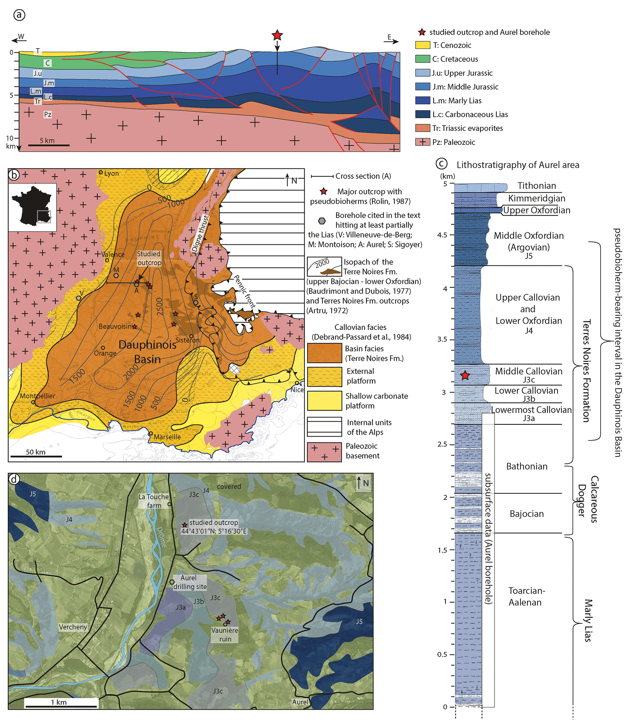
Figure 1Geological setting of the studied outcrop. (a) Cross section from the margin to the center of the Dauphinois Basin traversing the Aurel borehole (modified after Wannesson and Bessereau, 1999). (b) Facies map of the Dauphinois Basin for the Callovian (Debrand-Passard et al., 1984). Isopachs (in m), after Baudrimont and Dubois (1977), are shown for the basin facies represented by the Terres Noires Formation (middle Bathonian up to lower Oxfordian) in the central part of the basin. Outcrops of the Terres Noires Formation (after Artru, 1972) are noted by a darker shade of brown, and the locations of major pseudobioherms are marked by red stars (after Rolin, 1987). (c) Lithologic log of the Aurel area (Flandrin, 1974). The Aurel borehole penetrated the carbonate-dominated Dogger and the marly upper Lias. The pseudobioherms in the Aurel area are hosted in middle-Callovian sediments (red star on the log); in the Dauphinois Basin, they generally occur in upper-Bathonian to middle-Oxfordian deposits. (d) Geological map of the Aurel area (modified after Flandrin, 1974). Several pseudobioherms are poorly exposed near the Vaunière ruin; the studied pseudobioherm is located near La Touche farm.
2.1 Geodynamic context
The SE France Basin resulted from the Triassic rifting of the nascent Alpine Tethys (Lemoine et al., 2000; Masini et al., 2013). Triassic transgressive deposits above the peneplaned magmatic and metamorphic Variscan basement and Permo-Carboniferous basins entrenched therein consist of shallow-water siliciclastics and evaporites. The evaporites acted as a décollement level during the structuring of the basin. Deepening of the depositional environment during the Lower Jurassic coupled with large lateral thickness variations implies synsedimentary tilted-block tectonics linked to the paroxysmal phase of rifting (Lemoine et al., 1986). More uniform Bathonian to Tithonian deposits exceeding several kilometers in thickness are attributed to the onset of ocean spreading and associated thermal subsidence of the continental margin (Fig. 1b, c). During Triassic and Jurassic times, the SE France Basin was elongated along a NE–SW axis inherited from Variscan structures, whereas during the Cretaceous, the basin narrowed and acquired an E–W elongation due to the centripetal progradation of carbonate platforms. This change in the basin's geometry marks the limit between the so-called Dauphinois (Jurassic) phase and Vocontian (Cretaceous) phase during the evolution of the SE France Basin. E–W folding of the basin, initiated during the Aptian–Albian within a N–S compressional regime induced by the Pyrenean–Provencal orogeny, led to emersion during the Santonian. From the Oligocene onward, the Alpine orogeny overprinted previous structures by E–W compression.
2.2 Structural and stratigraphic setting
A 50 km long, E–W-oriented seismic section, crossing through the studied outcrop at Aurel, allowed the description of the local structural setting from the edge to the center of the basin (Fig. 1a; Roure et al., 1992; Wannesson and Bessereau, 1999). About 10 km east of Aurel, the abovementioned authors interpreted an offset in the basement reflection as evidence of two major westward-dipping normal faults rooted in the Paleozoic substratum. Early Jurassic tilted blocks are visible in the western part of the section, whereas they have been reactivated as reverse structures during compressive phases in the eastern part. The outcrop of Aurel is located in the middle of a large-scale domal structure formerly known as the “Aurel anticlinorium” (Artru, 1972). An exploration borehole drilled to a depth of 2800 m less than 1 km away from the outcrop provided information on the stratigraphic column below the outcropping Callovian strata, down to Toarcian–Aalenian deposits (COPEFA, 1967) (Fig. 1c, d). The uniform Toarcian–Aalenian “Marly Lias” has been partially penetrated for 1.5 km; the overlying 600 m thick “Calcareous Dogger” is a limestone–marl alternation dated Bajocian to Bathonian pro parte. The Bathonian to Oxfordian Terres Noires Formation is a uniform package of shales about 1.9 km thick in the Aurel area; it grades upward into limestone–marl alternations locally known as “Argovian” facies (Artru, 1972).
2.3 Potential oil and gas sources
Potential hydrocarbon source rocks of the SE France Basin have been studied in a report by the Institut Français du Pétrole (IFP, 1982a, b, c) and later by Wannesson and Bessereau (1999) and Mascle and Vially (1999). In stratigraphic order, the potential source rocks are as follows:
-
Carboniferous coals in post-Hercynian basins, known from outcrops and coal mines around the SE France Basin but speculative in the vicinity of Aurel;
-
the “Lias marneux” Formation (Marly Lias), >1500 m thick in the Aurel borehole, contains on average 0.6 % total organic carbon (TOC) (Wannesson and Bessereau, 1999);
-
the Terres Noires Formation, it yielded TOC values of 0.5 %–1 %. The common occurrence of oil in septarian concretions indicates that some hydrocarbons were generated in the Terres Noires Formation (Montenat and Patillet, 1968; Oddou, 2004).
2.4 Seep carbonates in the Jurassic SE France Basin
Lenticular carbonate bodies scattered in the Terres Noires Formation have been intensively studied over the past 60 years, starting with Orgeval and Zimmermann (1975). Artru and Gauthier (1966) and Artru (1972) proposed a first interpretation as sponge bioherms based on the abundance of disarticulated spicules. The lack of in situ frame-building organisms and the absence of evidence for relief above the seafloor, however, led Flandrin (1974) to question this hypothesis. To account for this uncertainty, Gaillard et al. (1985) and Rolin (1987) coined the term “pseudobioherm”, defined as “carbonate anomalies of early diagenetic origin, characterized by the predominance of endobenthic organisms”. Rolin (1987), Rolin et al. (1990), and Gaillard et al. (1992) noticed similarities between the numerous assumed chemosynthetic bivalves often associated with the pseudobioherms and the fauna discovered a few years earlier at cold hydrocarbon seeps (Suess et al., 1985). Since then, the hypothesis of hydrocarbon seepage has been developed for the Beauvoisin outcrop, located ca. 50 km to the south of Aurel, where 19 pseudobioherms are vertically distributed over 350 m inside an 800 m diameter perimeter (Gay et al., 2019, 2020). Gay et al. (2020) interpreted the Beauvoisin cluster as a long-lived giant pockmark and assigned the multiple generations of pseudobioherms to self-organized lateral migration of the fluid conduit over time.
The paleogeographic, structural, and stratigraphic context of the Aurel pseudobioherm has been determined at the regional scale based on the 1 : 50 000 geological map of the area (Flandrin, 1974) and the Aurel borehole (COPEFA, 1967). At the basin scale, the context has been evaluated using seismic data (Roure et al., 1992; Wannesson and Bessereau, 1999), isopach and facies maps (Debrand-Passard et al., 1984), and a few exploration boreholes compiled by Wannesson and Bessereau (1999). A 3D video of the pseudobioherm can be accessed online (https://fluid-venting-system.org/20m-tall-giant-seep-carbonate-chimney-Aurel-France, last access: 7 September 2021). In total, 20 rock slabs were cut (6 to 25 cm long, average of 13 cm) and polished, and 6 of them were oriented. They were studied in natural light and 365 nm ultraviolet (UV) light emitted by a Vilber VL-6 lamp (Eberhardzell, Germany). The 3D geometry of tubular structures was approached by closely comparing spaced sections such as those on opposite sides of 3 mm wide saw cuts. A total of 30 thin sections were investigated microscopically using plane and cross-polarized light, cathodoluminescence (CL), and UV epifluorescence (epi-UV). The CL was generated by a Cambridge Image Technology Ltd (CITL) system (Hatfield, United Kingdom), model CCL 8200 ink4 (12 kV, 450 mA). The epi-UV was emitted by a Leica (Wetzlar, Germany) EL 6000 light source mounted on a Leica DMRXP microscope (bandpass 340–380 nm). For X-ray diffraction (XRD), 27 samples were crushed manually in an agate mortar. The powders were analyzed with a Rigaku (Tokyo, Japan) Ultima IV diffractometer system equipped with a Cu X-ray tube, operated at 40 kV and 40 mA, and with a D/teX linear detector. Scans were run from 5∘ to 70∘2θ, with a step interval of 0.01∘2θ and a goniometric speed of 2θ ⋅ 120 s−1. The identification of all minerals was performed using the Rigaku PDXL2 software package and the International Centre for Diffraction Data (ICDD) Powder Diffraction File 2014 database. For stable oxygen and carbon isotope analyses, 37 samples of carbonate cements were selected. They were taken from polished blocks and rock chips using a handheld microdrill under the alternation of natural and UV light. Due to the size of the drill bit, only thick enough cements could be sampled individually, whereas grainstone was taken as bulk, including cement and grains. Samples were analyzed using a Kiel III automated carbonate preparation device coupled to a Finnigan MAT (Bremen, Germany) 252 isotope ratio mass spectrometer. Carbonate material was reacted with 100 % phosphoric acid for 10 min at 70 ∘C. The produced CO2 was then passed through the isotope ratio mass spectrometer for measurement at 44, 45, and 46; these measurements were alternated with the measurement of a calibrated reference CO2 gas. Instrumental precision was monitored by the analysis of NBS 18, NBS 19, and LSVEC reference material. Precisions are −0.05 ‰ for carbon and −0.14 ‰ for oxygen. All isotope data are given relative to the Vienna PeeDee Belemnite standard (V-PDB).
Four pseudobioherms have been identified less than 1 km away from the Aurel borehole (Fig. 1d; Artru, 1972). Three of them near the Vaunière ruin are covered by vegetation, and the relationships to the surrounding marls are not visible. In contrast, the pseudobioherm at “La Touche” is well exposed in lateral continuity with its background sediments; it is the focus of this paper. The host sediment consists of an alternation of mid-Callovian marls and thin platy limestone beds dipping 15∘ towards the ESE (log in Fig. 2). Two massive limestone bodies are exposed ca. 30 m apart along a small thalweg roughly oriented E–W. The upper one, on the northern bank of the thalweg, is a 7–10 m wide columnar body that interfingers with background marl–limestone alternations. It exposes a 15 m thick section of carbonate. The top is truncated by erosion and its lower part is cut by a low-angle fault (strike 040, dip 38W) filled by a centimeter-thick calcite vein. The vein shows crude striations with an azimuth of 095–125, without direct evidence for normal vs. reverse movement. The lower exposure is a westward-dipping subcircular section ca. 8 m in diameter on the southern bank of the same thalweg. It exposes the same facies as the upper exposure over 6 m. The relationships between the limestone body and its host sediments are poorly exposed, and its basal contact with the marls is not visible. The low angle and the orientation of the fault, perpendicular to the trend of the exposures, suggest that these are two parts of the same columnar body offset by a reverse fault later during the Alpine orogeny.

Figure 2Lithologic log of the middle-Callovian deposits in the pseudobioherm-bearing interval, logged about 20 m to the west of the upper part of the pseudobioherm, not affected by faulting; note marker beds A and B, which are easily recognizable in both host sediment and pseudobioherm.
4.1 Architecture of the pseudobioherm
Mapping of the southern flank (Fig. 3a, b) and eastern flank (Fig. 3c, d) shows that the columnar pseudobioherm is made up of stacked lenses. Individual lenses are a few tens of centimeters thick, and most of them pinch out within the massive body. They are separated by centimeter-thick marl layers with or without nodules, or they merge laterally or vertically. The center of an individual lens generally consists of massive limestone, which grades outward into nodular limestone that, in turn, splits laterally into several wedges grading into nodular marl. Nodules feather out into background marl over 1–2 m. Lenses in lateral continuation with limestone beds in the background sediments have the greatest lateral extension and are the most indurated. Overall, the pseudobioherm can be subdivided vertically into the following three units (from base to top):
-
Unit 1. At the base, Unit 1 is partially truncated by a fault. It mostly exposes nodular limestone grading laterally into nodular marls. Locally, some limestone lenses tend to be stacked vertically. The contact to Unit 2 above is defined by an abrupt, apparent 1–2 m lateral westward offset.
-
Unit 2. The lowermost bed of Unit 2 continues laterally into a prominent limestone bed in the background deposits classified as “marker bed A”. The middle portion of Unit 2 is made up of lenses consisting of nodular to massive limestone facies, locally organized in vertical stacks. The top of Unit 2 becomes increasingly massive. The transition from Unit 2 to Unit 3 is, once again, affected by an apparent 1–2 m northward offset, similar to the transition from Unit 1 to Unit 2.
-
Unit 3. The lowermost bed of Unit 3, classified as “marker bed B”, continues laterally into a limestone bed of the host sediment and is particularly massive. The southern flank is massive, whereas the eastern flank shows lateral grading of the massive limestone into the host sediment.
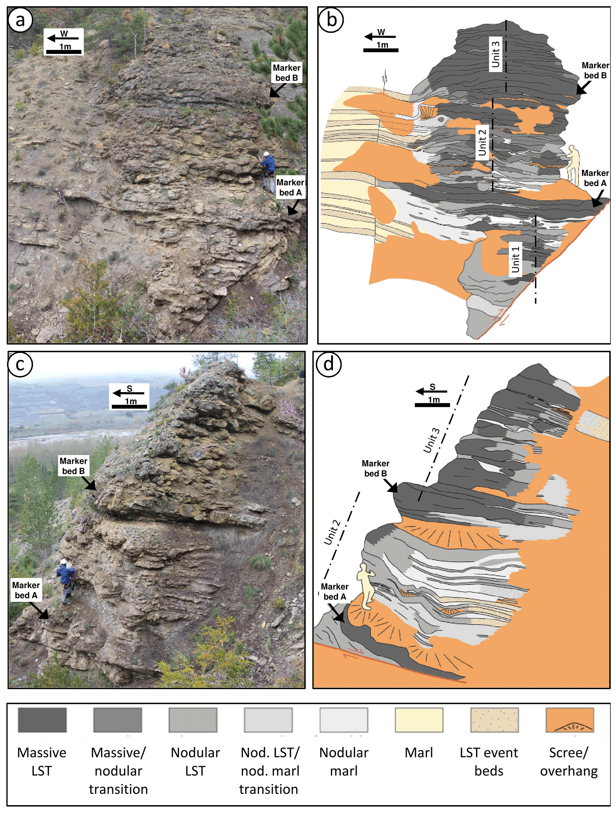
Figure 3(a, b) Image and interpretation of the southern flank of the Aurel pseudobioherm; dashed lines represent assumed axis of the pseudobioherm. (c, d) Image and interpretation of the eastern flank of the pseudobioherm. LST: limestone.
4.2 Facies of the pseudobioherm and background sediments
4.2.1 Facies 1 (F1): background consisting of marl–limestone alternation
In the studied area, the typical middle-Callovian facies consists of marls with intercalated limestone beds, a few centimeters to 20 cm thick, regionally known as “Marnes à plaquettes rousses” (marl with platy, rusty weathered beds; Fig. 4a; Artru, 1972; Flandrin, 1974). Individual limestone strata commonly show plane bed lamination and current ripples as well as occasional burrows at the base of a bed (Fig. 4b). The only common macrofossils are shells of Bositra sp., a bivalve typically associated to dysoxic settings (Meesook et al., 2009). In thin sections, both the background marl and the limestone beds exhibit a dominant wackestone fabric and have a similar grain content composed of microfossils and silt-grade quartz representing a calcilutite. They differ with respect to the matrix, which is shaly in marls (Fig. 4c) and microsparitic in limestones (probably recrystallized micrite; Fig. 4d). Laminae in limestone beds appear as millimeter-thick alternations of wackestone and packstone (Fig. 4e). The most abundant microfossils are spheres with a diameter of ca. 100 µm, likely calcispheres and/or recrystallized radiolarians, and sponge spicules (Fig. 4f). Echinoderm ossicles are rare. Most microfossils have been recrystallized into sparite. Sinuous filaments, up to several hundreds of micrometers in length and less than 10 µm wide, correspond to the structures identified as fragments of exfoliated shells of Bositra sp. (Fig. 4c; Negra et al., 2011).
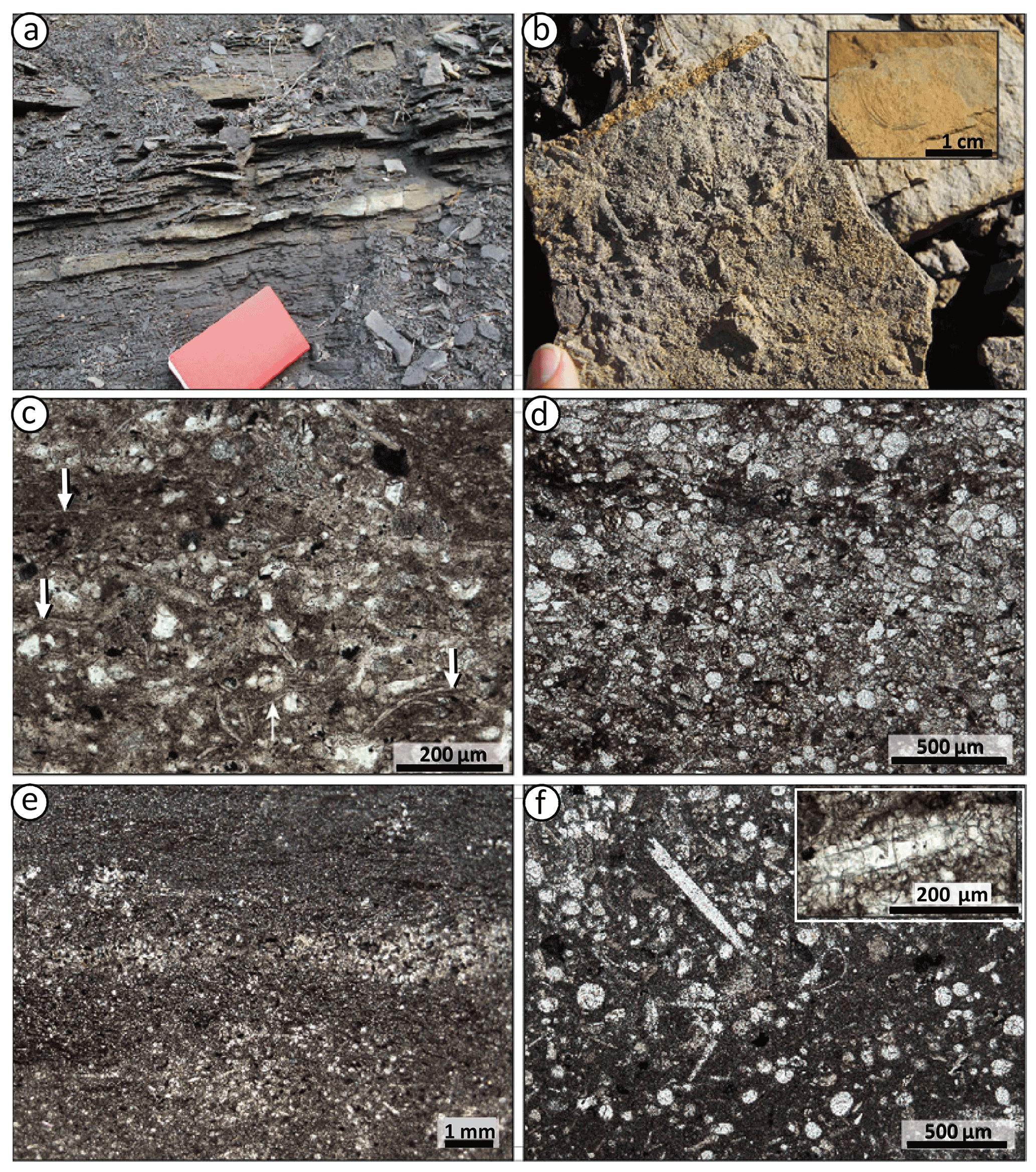
Figure 4Background Facies 1 (F1). (a) Typical alternation between marl and limestone showing platy bedding. (b) Basal surface of a limestone slab with radiating burrow (Gyrophyllites multiradiatus); the inset shows the bivalve Bositra, the only common fossil in F1. (c) Marl with numerous filamentous structures (white arrows) interpreted as disaggregated Bositra shells. (d) Limestone showing the same microfossil content as the marl but in microsparitic matrix. (e) Limestone consisting of alternating packstone and wackestone laminae. (f) Marl with numerous recrystallized microfossils in a micritic matrix; circular objects are interpreted as calcispheres or radiolarians; the inset shows a tubular structure interpreted as a sponge spicule.
4.2.2 Facies 2 (F2): nodular marl
This facies comprises the transition between background sediments and the pseudobioherm limestone body (Fig. 5a). It consists of micritic limestone nodules embedded in a marly matrix exhibiting a matrix-supported floatstone texture. The most common nodules are isolated prolate ellipsoids with the long axis parallel to stratification. The nodules are 1–2 cm in diameter and up to 5 cm in length. Some show rod-like, straight, or curved protuberances (Fig. 5b). Nodule density increases towards the limestone body. At higher concentration, adjacent nodules commonly aggregate into peanut-shaped clusters of two or three, in a pattern similar to that described in Beauvoisin by Gay et al. (2019, 2020). In thin sections, nodules show a wackestone texture containing the same grain types as the encasing marl and limestone beds described above, such as microfossils and detrital silt. As peloids represent a key component of F4 (see below), we paid particular attention to their possible presence. Neither direct observation nor fluorescence or cathodoluminescence provided any evidence of their (former) presence in F2. Nodules are weakly fluorescent under UV light (Fig. 5c, d). F2 shows a gradual transition to F3, comprising nodular limestone as the concentration of nodules increases towards the axis of the pseudobioherm and individual nodules may become amalgamated. A threshold of ∼ 50 % nodules marks the limit between F2, which is sensitive to weathering as it is a nodular marl, and F3, which remains rather massive and less prone to weathering. The different weatherability of the two facies was used for pseudobioherm facies mapping of zones that are difficult to access (Fig. 3).
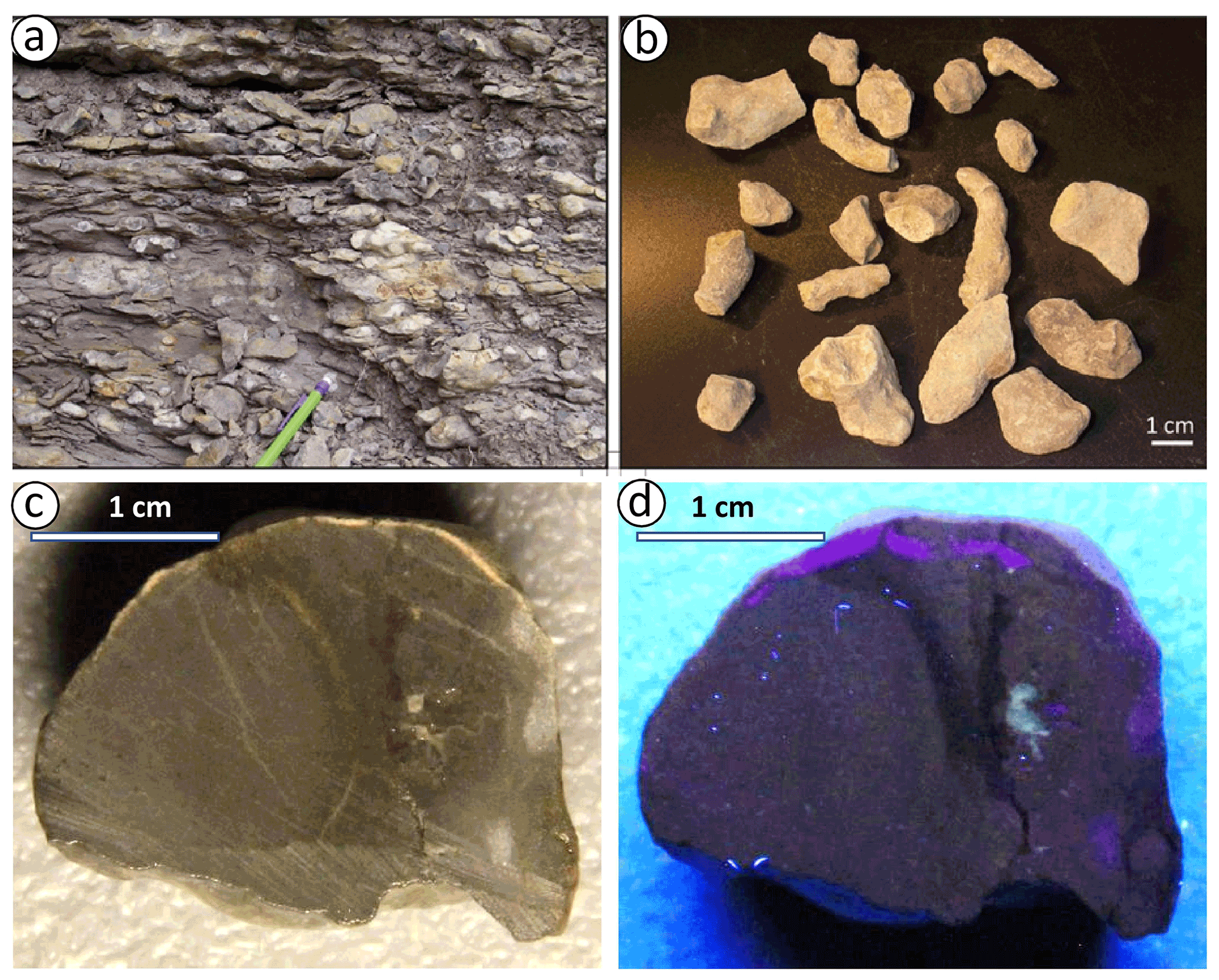
Figure 5Facies 2 (F2): nodular marl. (a) Outcrop view. (b) Individual nodules and nodule clusters. (c, d) Cross section of a nodule under natural (c) and UV light (d); the vertical parting in the middle of the sample that shows a darker color in (c) but is non-fluorescent in (d) is suggestive of previous boundary between two, now clustered nodules.
4.2.3 Facies 3 (F3): nodular limestone
Across the F2–F3 transition, nodules become more frequent and the matrix between the nodules is strongly indurated and shows pervasive rusty speckles (Fig. 6a). The nodules are weakly fluorescent in a nonfluorescent matrix as in F2 (Fig. 6b). In contrast to nodular marl, the nodular limestone represents a nodule-supported rudstone texture. In thin sections, the rusty speckles consist of euhedral crystals of saddle dolomite about 100 µm in size, locally replacing and overgrowing carbonate bioclasts (Fig. 6c). The rusty color of the crystals is due to oxidation of iron along cleavage planes and gives the matrix its speckled macroscopic appearance.
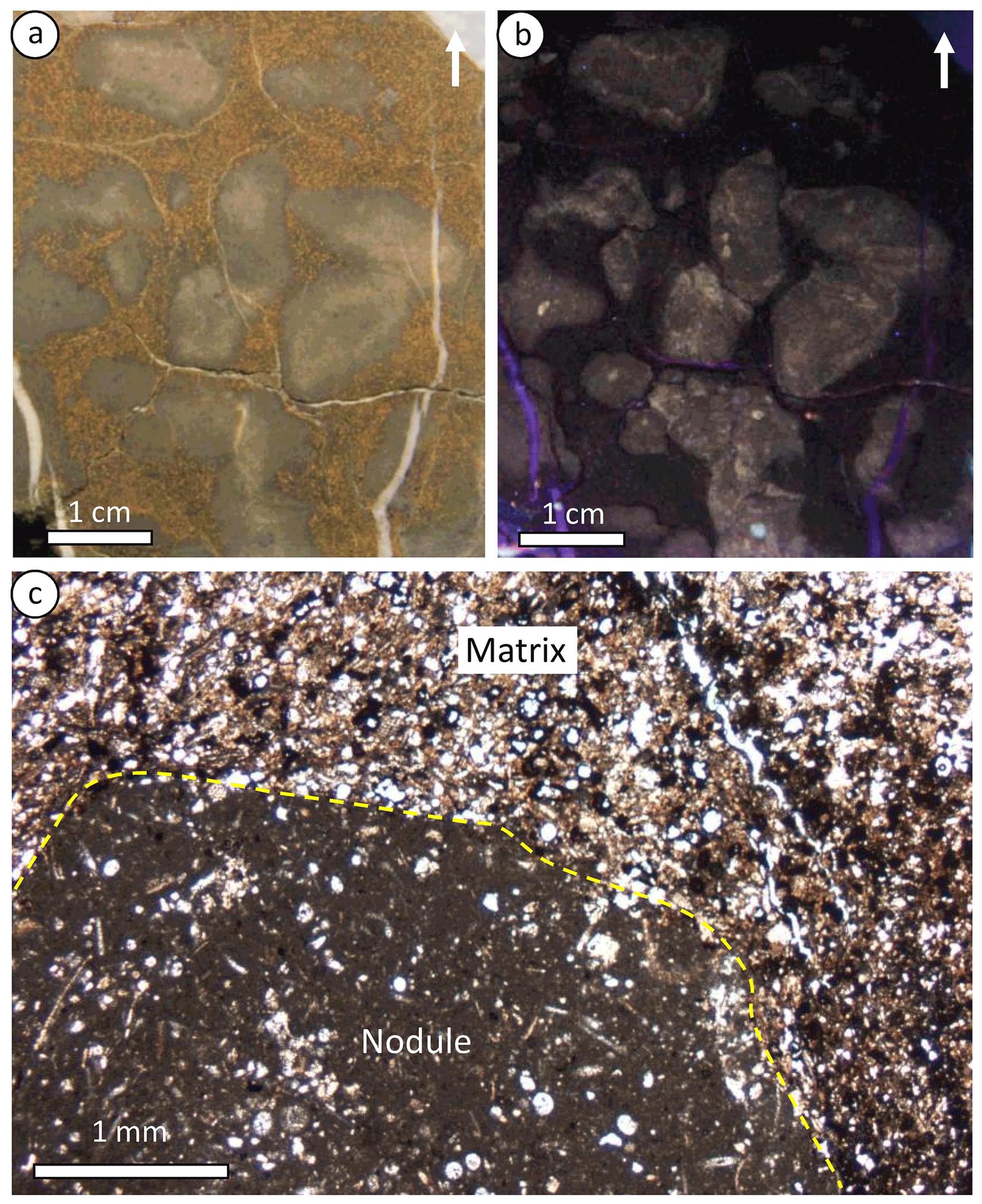
Figure 6Facies 3 (F3): nodular limestone. (a, b) Vertical section under natural (a) and UV light (b); arrows point upward. (c) Photomicrograph showing contact between a nodule and matrix (marked by yellow dashed line). Grain packing in the matrix is denser than in the nodule, suggesting cementation of the nodule prior to compaction.
4.2.4 Facies 4 (F4): massive limestone
Macroscopic observations and macrofauna
Facies 4 (F4) consists of gray to brownish limestone that typically interfingers with the nodular limestone. In contrast to the background sediments, no primary sedimentary structures or laminations have been observed, although laminated limestone beds of the surrounding host sediment occur in continuity with prominent lenses of the pseudobioherm. Severe weathering hinders the observation of facies details in the field, except on a few isolated surfaces. One of these, which is ca. 30 cm × 70 cm, exposes the feathering out of F4 into marker bed A that extends farthest away from the axis of the pseudobioherm (Fig. 7a). The surface shows three articulated bivalves (Fig. 7b, c, d). In addition, a single, internal mold of a 6 cm long articulated specimen found on the margin of the pseudobioherm was identified as a lucinid, possibly Beauvoisina carinata (Kiel et al., 2010), although it seems to be more asymmetrical than the type specimen and the diagnostic carinate lunule could not be recognized on the mold (Fig. 7e, f). A few small gastropods were also observed in the outcrop and in cut samples (Fig. 7g), indicating that benthic mollusks were relatively common and diverse in F4. Facies 4 commonly shows ∼ 5 mm diameter cement-filled tubular structures with the characteristic branching pattern of Thalassinoides/Spongeliomorpha (Fig. 7h).
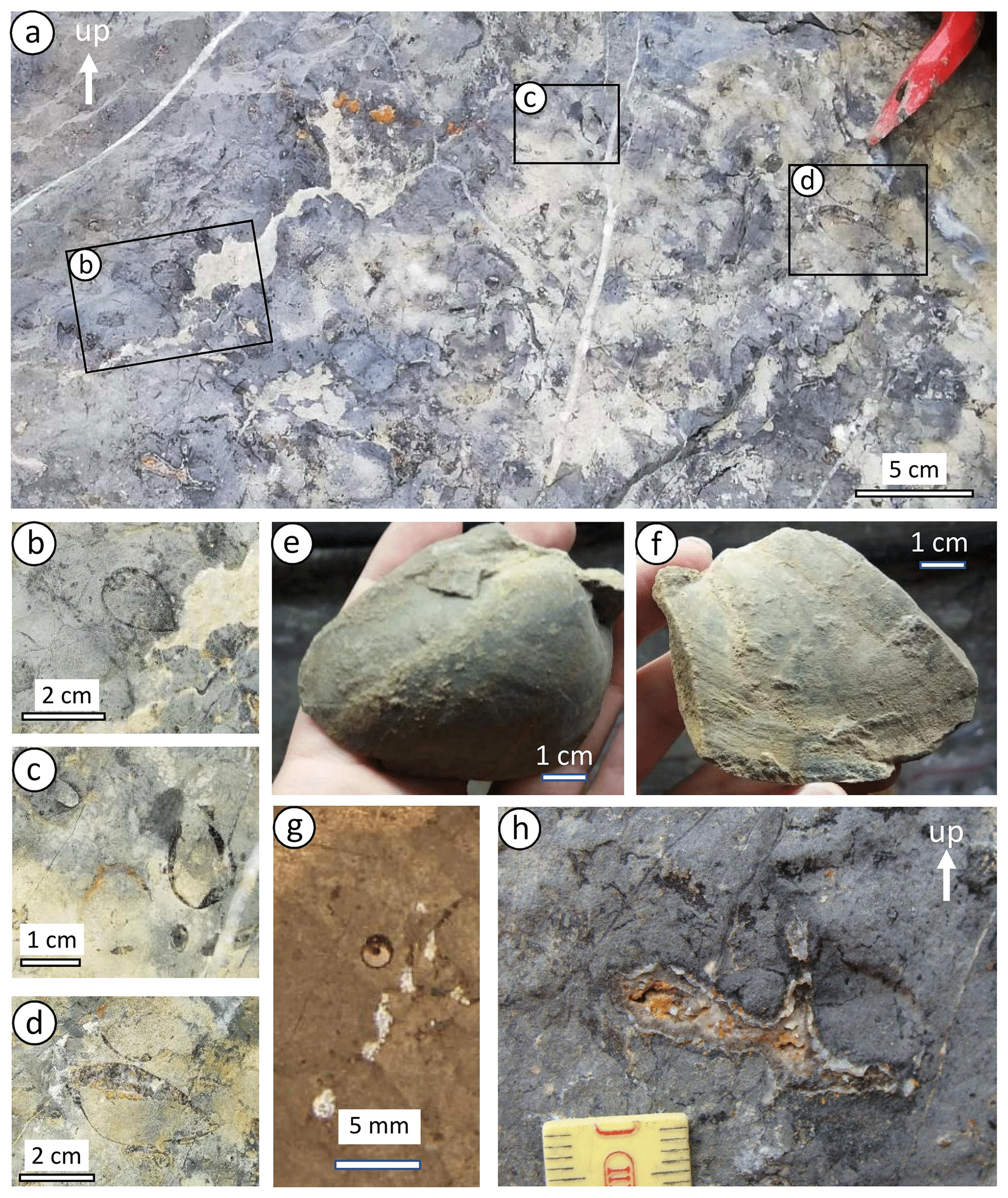
Figure 7Facies 4 (F4): massive limestone and associated fauna. (a) Weathered surface showing three bivalves shown in (b) to (d) in detail, apparently belonging to different species. (d) Bivalve with geopetal filling. (e, f) Two valves of the only lucinid found (likely Beauvoisina carinata; Kiel et al., 2010). (g) Section of a small gastropod. (h) Bedding plane view of Thalassinoides (smaller graduations on the tape measure are 1 mm apart).
Fabric and bioturbational structures
The fabric is best characterized by using combined plane and UV light on cut sections. Macroscopically, most samples show a complex mosaic of patches, which under UV light appear to consist of low-fluorescence micrite and calcarenite exhibiting various levels of fluorescence (Fig. 8). At hand lens magnification, the calcarenitic limestone consists of peloid grainstone with fluorescent cement. The proportions of micrite and calcarenite vary, with the former ranging from 20 % to 50 % and the latter ranging from 80 % to 50 %. Near the transition to Facies 3, where micrite is enriched (∼ 50 %) it forms continuous domains, whereas calcarenitic material constitutes a network of 2–3 cm wide patches surrounded by a darker, commonly fluorescent halo (Figs. 8c, d; 9a, b, c). This texture evidences pervasive bioturbation, with two populations of burrows. Calcarenitic domains 2–3 cm in width are referred to as “large burrows' and those 0.5–1.5 cm in width are termed “medium burrows” in the following. In addition, numerous millimeter-diameter burrows (“small burrows”) filled by fluorescent cements are scattered throughout the section. In calcarenite-rich samples, micrite occurs as low- to moderate-fluorescence patches, 1 mm to 2 cm in diameter, angular to subrounded, commonly surrounded by a dark halo. The micrite domains are interpreted as remnants of the initial sediment that were not reworked by burrowing. They are described as so-called “pheno-intraclasts” floating in the dominant peloid grainstone (Fig. 8e, f, g), in contrast to true intraclasts defined as reworked particles. The overall fabric of calcarenite-rich areas reflects pervasive bioturbation, including but likely not restricted to the large burrows:
- a.
Large burrows
The margins of large burrows, as defined by their dark halo, are rather irregular. The geometrical arrangement of the large burrows suggests that they constitute a complex branched network (see Cunningham et al., 2012). They are filled with sediment identical to that of the background (typically peloid grainstone of packstone), which is indicative of passive fill. Large burrows have a variable intensity of fluorescence, with peloid grainstone being the most fluorescent. At the transition from F3 to F4, granular/fluorescent material becomes progressively enriched. The more granular/fluorescent patches dominantly crosscut less fluorescent ones. (Fig. 8d).
- b.
Medium burrows
The morphology of the medium burrows is best observed by narrowly spaced parallel sections on opposite sides of a saw cut (Fig. 9a, b). Some burrows show abrupt changes in direction and/or diameter between closely spaced parallel sections (Fig. 9a, b, d). Burrows commonly show a dark halo around the cement fill, which, in some cases, can be followed into the sediment, defining a subcircular shape (Fig. 9e). Its lower part is filled with sediment, and its upper part is filled with cement. Within the burrows, the contact between sediment within burrows and cement above is planar, with an apparent dip of 0–30∘ (Fig. 9e), indicating partially passive fill. Some burrows show laminated sediment fill recording multiphase passive infill. Macroscopically, the lumen of most medium burrows shows a concentric bipartite cement fill with a ca. 1 mm thick tan, translucent, continuous outer rim around the lumen and a white to yellow/gold final axial fill (Fig. 10a, b). Both the dark halo and the outer rim are brightly fluorescent, in contrast to the slightly fluorescent final fill (Figs. 9c; 10a, b). Burrow margins commonly show irregularities that might have resulted from burrow excavation; corrosion by fluids circulating in the burrows, in particular when they contain (hydrogen) sulfide; or local collapse of the burrow top. The distance between medium burrows ranges from 2 to 10 cm with an estimated average of 5 cm. Burrows show subvertical, oblique, and subhorizontal segments, without preferential orientation. The abrupt changes in orientation and diameter over short distances and the coexistence of vertical, oblique, and horizontal segments are diagnostic of burrows of the Thalassinoides – Spongeliomorpha suite (e.g., Cunningham et al., 2012; Knaust, 2017). These are produced by decapod crustaceans that may penetrate as deep as 2 m or more below the seafloor (e.g., Sarnthein, 1972; Pemberton and Buckley, 1976). Thalassinoides corresponds to smooth-walled burrows, which are lined with mucus in soft sediment and unlined in sediment stiff enough to remain open, and Spongeliomorpha corresponds to burrows scratched by body appendages, indicating firm sediment (Wetzel and Uchman, 1998). Medium burrows occur preferentially in calcarenite and appear to get around pheno-intraclasts (Fig. 8a, b, e, f, g). However, in calcarenite patches, they do not follow specific patterns that could suggest a spatial relationship between large and medium burrows (Fig. 8).
- c.
Small burrows
Small, cement-filled burrows are more easily visible under UV light. Some of these small burrows are directly connected to medium burrows while most appear isolated in vertical section (Fig. 9a, c, f), but out-of-plane contact with medium burrows appears likely. Their geometry, size, and fill match the characteristics of Trypanites, representing boring in hard substrate. Small burrows may cut across pheno-intraclasts and/or peloid limestone, or locally follow the contact between the two.
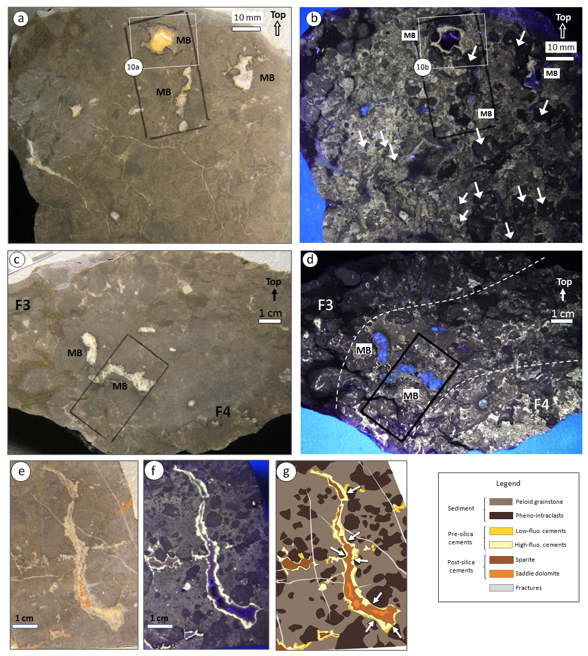
Figure 8Fabric of intensely bioturbated sediment. (a) Natural light and (b) UV fluorescent light, Facies F4. White arrows in (b) point at some of the micrite pheno-intraclasts. Note the variability of pheno-intraclasts in roundness and size. MB: medium burrow. (c) Natural light and (d) UV fluorescent light, transition from F3 to F4. In both samples, MBs appear independent of variations in the fabric around them; black rectangles were drawn for thin section selection. (e) Natural light, (f) UV fluorescent light and (g) line drawing, Facies F4, unoriented vertical section. White arrows in (g) show points where the burrow's edge is tangent to pheno-intraclasts.
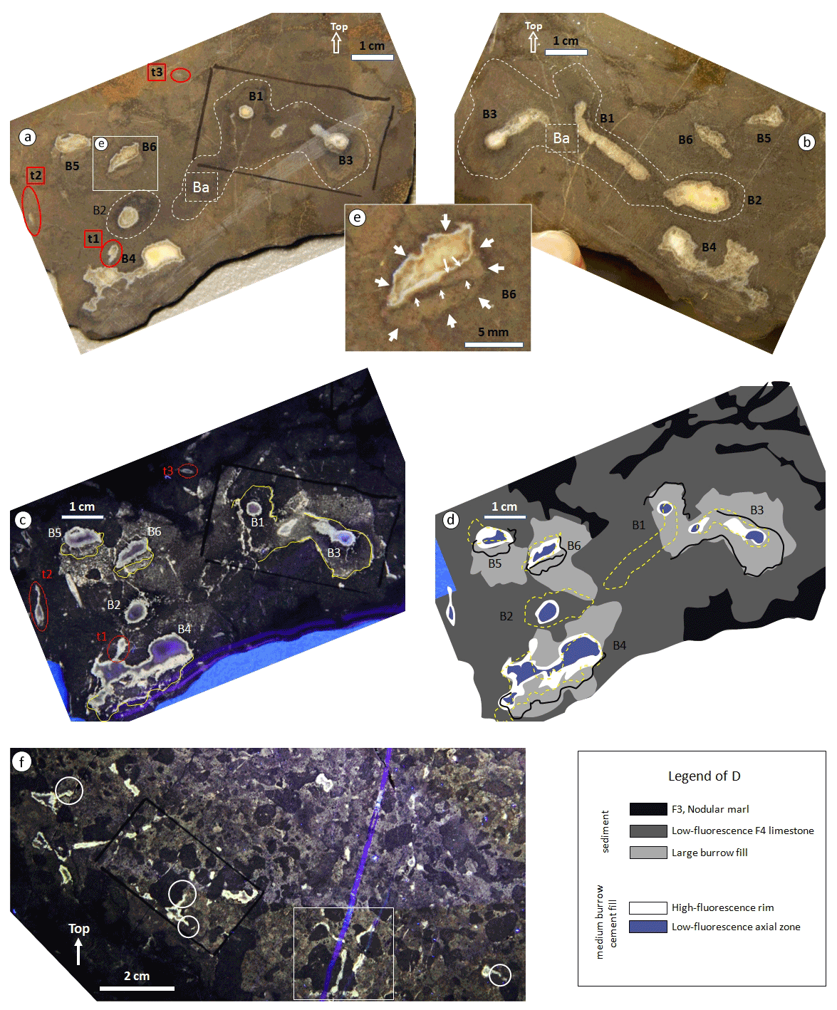
Figure 9Burrow architecture in F4. (a, b) Opposing sides of a saw cut, ca. 3 mm apart; Note three types of burrows: large burrows (one marked as Ba) surrounded by white dashed line; medium burrows (partly) filled with white-yellowish cement (labeled B1–B6); small burrows (t1–t3) encircled in red. The white rectangle in (a) is the position the close-up shown in panel (e). (c) UV-light view of the section shown in (a). Yellow lines follow main dark halos, as marked in (a). (d) Line drawing of (c); black lines are dark halos copied from (c), yellow dotted lines are the position of dark halos on the opposite side of the saw cut (drawn on b and flipped), illustrating changes in burrow size and orientation across the 3 mm gap between the sections. (e) Close-up of B6 marked in (a) showing burrow surrounded by dark halo (bold arrows) and half-filled with geopetal sediment; thin white arrows show halos inside the geopetal filling. (f) Cross-cutting relationships between burrows (UV fluorescence). White circles point at small burrows connected to adjacent medium burrows. The white rectangle highlights longitudinal cross sections of small burrows. Black rectangles were drawn during the sample preparation process for thin section selection
4.2.5 Relative timing and tiering
Based on crosscutting relationships, it is possible to distinguish successive phases of burrowing evidenced by intensely mixed, homogeneous sediment, overprinted by abundant shallowly produced, large Thalassinoides, which are, in turn, crosscut by deep but scarcer and smaller Thalassinoides or Spongeliomorpha; occasional Trypanites borings entrenched into the cemented margins of the latter traces represent the last phase of bioturbation. In addition, the nonfluorescent wackestone occurring in patches has a grain content similar to the background sediment of Facies 1 or to the nodular facies 2 and 3. In contrast to the background sediment, it never shows lamination nor stratification on the scale of limestone–marl alternations of the host sediment. Nonetheless, the processes that produced layering and lamination must have been active at the pseudobioherm site as in the surroundings. The uniform texture of the wackestone, therefore, reflects efficient mixing of the uppermost soupy/soft sediment by near-surface burrowing organisms producing so-called biodeformational structures that overprint preexisting structures but do not constitute distinct traces (e.g., Schäfer, 1956; Wetzel, 1991). Consequently, it is possible to distinguish four phases of endobenthic activity recorded by
-
tier 1 – comprising biodeformational structures homogenizing soft sediment into wackestone (Phase 1);
-
tier 2 – constituted by burrows emplaced in soft to firm sediment mainly by large decapod crustaceans and filled by peloids (Phase 2);
-
tier 3 – characterized by burrows produced by smaller decapod crustaceans in sediment that is so stiff that the tunnels remained open (Phase 3); and occasionally,
-
tier 4 – solely evidenced by Trypanites borings originating at the walls of tier-3 burrows (Phase 4).
4.3 Microfacies and diagenesis
Tier 1: micrite pheno-intraclasts. Marl/calcilutite homogenized by biodeformational bioturbation in tier 1 before it was cemented is only found as isolated remnants between burrows of deeper tiers. In thin section, these pheno-intraclasts consist of shaly silty bioclastic wackestone, with the same grain types as in background sediment (Fig. 4c), such as calcispheres, sponge spicules, and bivalve fragments (Fig. 10c).
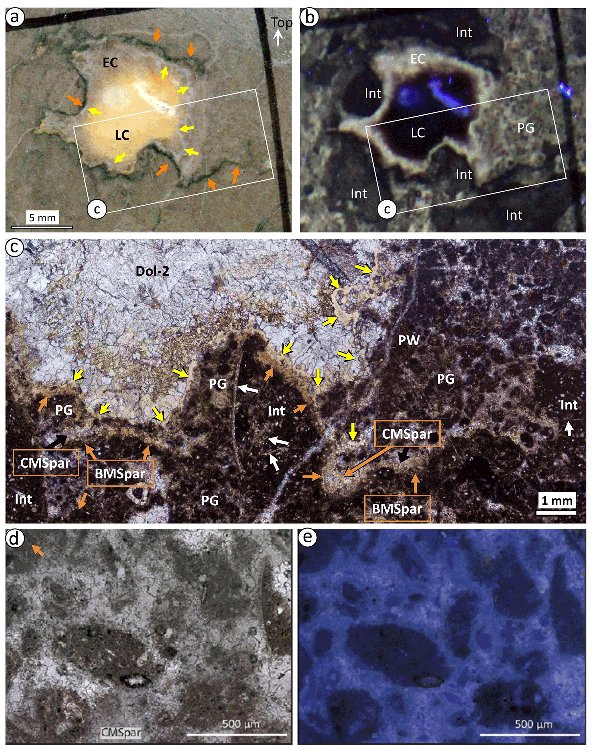
Figure 10(a, b) Close-up of Fig. 8a and b showing the details of burrow infill; white rectangle marks the position of the thin section close-up in (c). (a) Natural light view; EC: early cements, LC: late cements; the orange arrows mark a dark halo surrounding the burrow on the left side and opening into sediment on the right side; yellow arrows mark a thin, continuous, milky white cement rim following the dark halo on the left side of the image but following the sediment-cement contact on the right side. (b) UV fluorescence view indicates that the fluorescent halo expands on the right side into peloid grainstone (PG); the blurry appearance results from the diffusion of light emitted from fluorescent parts into non-fluorescent ones; Int: micrite pheno-intraclasts; pheno-intraclasts, like nodules in F2 and F3 exhibit a low level of fluorescence. The brightly fluorescent zone is bounded by the dark rim on the outer side (orange arrows in a) and the white rim on the inner side of the burrow (yellow arrows in a). (c) Microphotograph of the sample shown in (a) and (b) (plane-polarized light view); the dark halo (orange arrows) corresponds to the superposition of brown and clear microsparite layers (BMSpar and CMSpar, respectively), with BMSpar directly covering the burrow wall. The white rim (yellow arrows) consists of beige chalcedony (for details, see Fig. 11). The white arrows point to shell fragments, PW: peloid wackestone, Dol-2: late saddle dolomite. (d, e) Photomicrographs of peloid grainstone in F4. (d) Internal texture of the peloids in plane-polarized light; (e) As (d) in UV epifluorescent light.
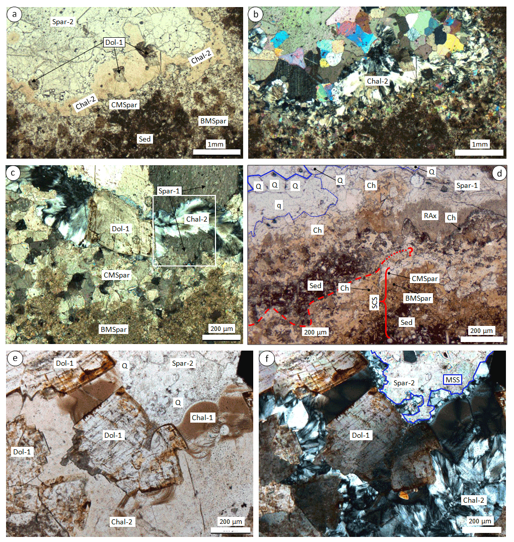
Figure 11Cements within Phase-3 burrows and host sediment. (a, b) General view of burrow margin in plane-polarized light (a) and cross-polarized light (b). Note continuous rim of beige chalcedony (Chal-2) associated with saddle dolomite (Dol-1); BMSpar and CMSpar: brown and clear microspar, respectively; Sed: sediment. (c) Details of the relationship between Chal-2 and carbonate cements in cross-polarized light; Spar-1: first generation of sparite cement; the white rectangle: Chal 2 cutting across a single sparite crystal. (d) Burrow rim in plane-polarized light showing one sediment–cement sequence (SCS, red bracket) capped by sediment in the left part. The cements are heavily replaced by chalcedony. Red line: top of SCS, dashed where observed and dotted where inferred. Radiaxial gray calcite crystals (RAx) locally cap the SCS. Blue lines (dashed at base, solid at top) outline a patch of quartz with anhedral (q) capped by euhedral (Q) crystals; euhedral crystals are aligned roughly parallel to burrow margin wall. (e, f) Main phases of silicification in plane-polarized light (e) and cross-polarized light (f); Chal-1: botryoidal chalcedony precipitated freely at the tube wall, Q: euhedral quartz also overgrown on a free surface, Chal-2 and the associated saddle dolomite Dol-1 replaced both preexisting carbonates and Chal-1. Note the extinction pattern of Chal-2 characterizing “flamboyant chalcedony”. The blue zigzag line marks the main silicification surface (MSS). For details, see the text.
Tier 2: large burrows and their infill. Phase-2 burrows are filled with peloid grainstone. Peloids have a narrow size range of fine to medium sand, typically 200–300 µm (Fig. 10d). Their morphology is ovoid, and their internal fabric is identical to that of pheno-intraclasts of F4 and nodules of F2 and F3, consisting of silt/microfossil wackestone. Epifluorescence microscopy confirms the macroscopic observations that fluorescence mainly comes from microsparite cementing the grainstone (Fig. 10e).
Tier 3: medium burrows and their infill. Cements composing the dark halo at the burrow boundary are commonly interlayered with sediment and, thus, coeval with passive burrow infill (Fig. 9e). In thin section, the dark halo shows the same succession of cements irrespective of their position, between sediment laminae or at the sediment–cement boundary (Fig. 10a, b, c). It starts with a sediment-coating, 0.1–0.3 mm thick layer of brown microsparite (BMSpar), commonly covered by 0.2–0.5 mm thick clear microsparite (CMSpar, Figs. 11a, c, d, 12a). CMSpar, in turn, is locally covered by sets of radiaxial gray carbonate crystals (RAx; Fig. 11d). Sediment within burrows can show geopetal features above this succession, in some cases covered by a similar BMSpar–CMSpar couplet. The sediment–BMSpar–CMSpar succession has been observed up to three times (Fig. 12a). Individual microspar crystals are continuous across the boundary between brown and clear microspar (Fig. 12b, c). At high magnification, the brown color of BMSpar is due to bush-forming sets of brown filaments (Fig. 12d) whose diameters are close to the limit of optical resolution of ca. 1 µm. Individual “bushes” are about 100 µm in diameter and have a smooth, convex margin. Neither the abundant inclusions that characterize BMSpar nor the calcite cementing the filaments are fluorescent, in contrast to CMSpar which shows both general mineral fluorescence and brightly fluorescent fluid inclusions (Fig. 12e, f, g, h). Fluorescent inclusions appear most abundant along the contact between BMSpar and CMSpar (Fig. 12f). Early diagenetic cements are, thus, arranged into repetitive sequences made of sediment–BMSpar–CMSpar, occasionally capped by radiaxial sets of calcite crystals; these will be referred to as “sediment–cement sequences”. Above the last sediment–cement sequence, the dominant cement is sparry calcite (Spar-1; Fig. 11c, d), with the occasional presence of botryoidal chalcedony (Fig. 11e, f). Above the sediment–cement sequences and occasional Spar-1, there is a continuous 100–300 µm thick rim of white cement, which consists of a high-relief light brown mineral in thin section (Figs. 10c, 11a) that shows the typical texture of flamboyant chalcedony in cross-polarized light (Sander and Black, 1988; Fig. 11b, f). This mineral, noted Chal-2, generally occurs in association with saddle dolomite (Dol-1) and is commonly covered by euhedral quartz crystals (Fig. 11d, e, f). Flamboyant chalcedony commonly crosscuts single sparite crystals (Fig. 11c). It locally replaces older cryptocrystalline botryoidal chalcedony (Chal-1; Fig. 11e, f). Below the continuous rim, patches made of an intricate mixture of Chal-2 and Dol-1 crystals commonly replace the upper part of sediment–cement sequences, thereby defining a complex, digitated surface of replacement. Silica replacement never occurs above a surface characterized by the occurrence of euhedral quartz crystals but can locally affect any of the underlying cements, except those cementing grainstone. We refer to this surface as the “main silicification surface”, which can be traced as the envelope of euhedral quartz crystals (see Fig. 11d, f). Cements above the main silicification surface are dominantly sparry calcite (Spar-2) and/or saddle dolomite (Dol-2), in variable proportions (Figs. 10c, 11a). Subordinate minerals include fracture-filling microcrystalline chalcedony and occasional sulfates (barite–celestite mixtures).
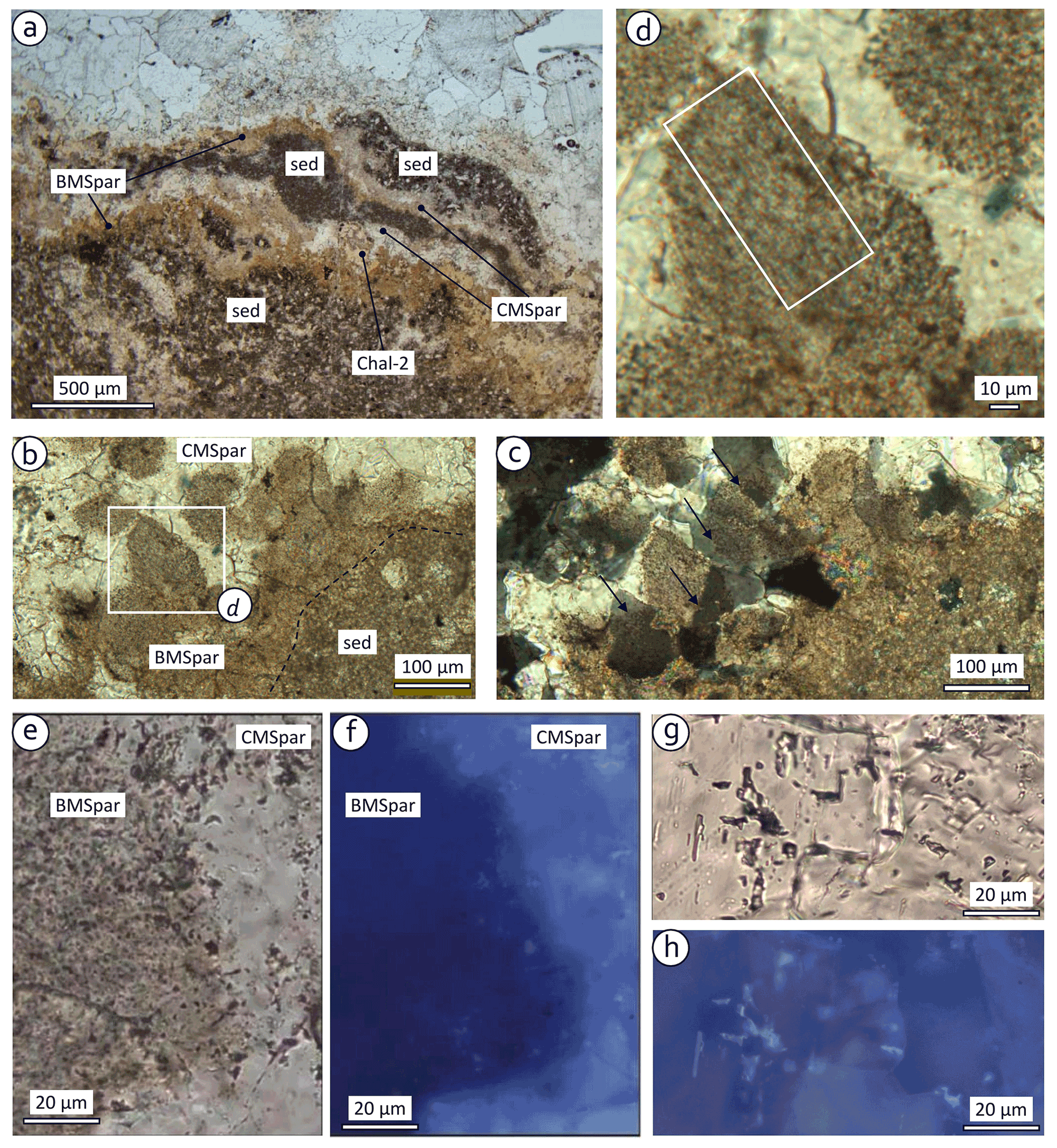
Figure 12Microphotographs showing details of sediment–cement sequences. (a) Repeated sequence of sediment (sed), brown microsparite (BMSpar), and clear microsparite (CMSpar), locally overprinted by chalcedony (Chal-2). (b) Detail of BMSpar–CMSpar contact (black dashed line follows the underlying BMSpar–sediment contact); BMSpar appears as a set of filamentous “bushes”; the white rectangle marks the area shown in detail in (d). (c) As (b) in cross-polarized light, showing individual microspar crystals straddling across BMSpar–CMSpar boundaries (marked by black arrows). (d) Close-up of filamentous bush; note the elongate brown inclusions within clear crystal, particularly in white rectangle. (e, f) BMSpar–CMSpar contact in plane light (e) and UV epifluorescent light (f); fluorescent inclusions near the margin of BMSpar following oblique contact between BMSpar and CMSpar into the thin section. (g, h) Typical CMSpar in plane light (g) and UV epifluorescent light (h), fluorescence originating from both fluid inclusions (bright white) and microspar (dull yellow).
4.4 Stable isotopes
The stable carbon and oxygen isotope data of the studied carbonates exhibit a trend between the marl sample with δ13C of 1 ‰ and δ18O of −2.2 ‰ and a cluster centered at δ13C of −10 ‰ and δ18O of −1.5 ‰ (Fig. 13a; Appendix A). Samples of the 13C-depleted cluster comprise microsparitic cements of the sediment–cement sequences (BMSpar and CMSpar) and Spar-1; all of these cements predate the main silicification event (Fig. 13b, c). It also includes some peloids and some nodules. The majority of nodules and peloids and all micrite pheno-intraclast samples follow a mixing trend between marine sediment (F1 marl) and the 13C-depleted cluster. The δ18O values vary in a narrow range from −1.8 ‰ to −2.2 ‰ for early cements precipitated at seafloor temperature and from −1.1 ‰ to −2.1 ‰ for peloids and micrite pheno-intraclasts. Five of the six samples of saddle dolomite have similar values (−0.9 ‰ to −2.2 ‰), whereas the last one is the most depleted, showing −7.5 ‰.
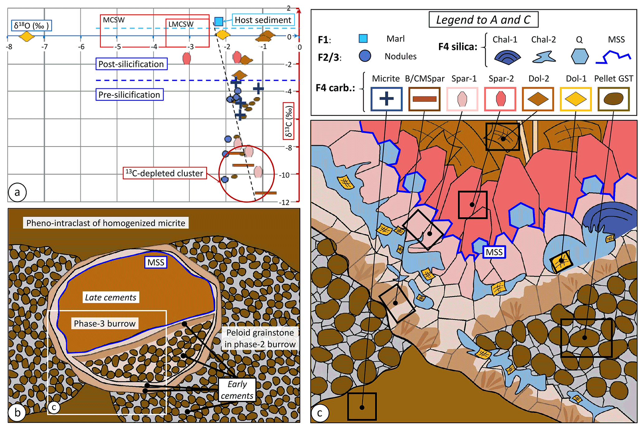
Figure 13Stable C and O isotopes and microfacies. (a) Sedimentary and diagenetic carbonate phases encountered in the Aurel pseudobioherm in δ13C–δ18O plot; the position of samples of facies F1 to F3 is shown in Fig. 14. MCSW: middle-Callovian seawater composition; LMCSW: subset for the lower part of the middle Callovian (Pellenard et al., 2014). (b) Fabric and microfacies of F4 recording successive phases of bioturbation; the white box indicates the general position of (c). (c) Schematic geometric relationships between sediment and various cement generations within Facies F4; black boxes mark minimum size of samples drilled for isotope analysis, some likely mixing different phases like peloid grainstone and BMSpar/CMSpar. GST: grainstone. Chal-1: early botryoidal chalcedony; Chal-2: later replacement chalcedony; Q: euhedral quartz crystals; MSS: main silicification surface; BMSpar and CMSpar: brown and clear microsparite, respectively; Spar-1: pre-silicification sparite; Spar-2: post-silicification sparite; Dol-1: syn-silicification saddle dolomite; Dol-2: late saddle dolomite; GST: grainstone. For details, see the text.
The main proxies to identify seep carbonates in the rock record are the presence of specific methanotrophic fauna (e.g., Kiel, 2010) and/or the carbon isotope signature of the carbonate minerals, generally considered diagnostic if δ13C depletion exceeds −30 ‰. In Aurel, no sample meets the latter criterion. Similarly, the scarcity of CH4-related macrofauna with one single specimen of a lucinid does not provide compelling proof regarding the nature of the whole carbonate body. The most convincing evidence comes from combined analysis of bioturbation, early diagenesis in and around burrows, and isotope geochemistry.
5.1 Alternatives to the bioturbation interpretation
The homogeneous character of micrite pheno-intraclasts and the tubular structures are interpreted as the result of bioturbation, affecting sediment of soupy consistency in the upper few centimeters of the subseafloor and firm sediments below, respectively. Could these features be abiogenic and simply result from gas escape itself? Homogenization by ascending fluid, known as fluidization, occurs in non-cohesive material when the fluid ascent velocity exceeds the settling velocity of the particles (Allen, 1992). In the case of cohesive material interacting with gas, however, observations systematically indicate bubbling at discrete points rather than pervasive ebullition (Dupré et al., 2020). Both analogue and numerical modeling have shown that individual bubbles move as discrete lenticular hydrofractures within the cohesive material (Boudreau, 2012; Katsman et al., 2013). On the other hand, homogenization by bioturbation by meiofauna in the first few centimeters below the seafloor is a well-documented phenomenon (Wetzel, 1983; Wetzel and Uchman, 1998; and references therein). Moreover, the presence of discrete open conduits in the subseafloor ensures that any upcoming fluid (liquid or gas) will migrate along these conduits up to discrete venting points rather that homogenize the whole shallow subseafloor (Blouet et al., 2021c). Could the tubular structures interpreted as burrows be related to other structures – for instance, to abiogenic gas conduits? Generally speaking, due to its buoyancy, gas tends to migrate vertically in homogeneous and isotropic sediment. As observed for sand injectites and demonstrated by analogue modeling, deflection to the horizontal can occur where changes in lithology/cohesion and/or permeability make it more energy effective for ascending gas to follow a permeable, non-cohesive bed and lift the cohesive overburden than to (hydro) fracture it. This phenomenon typically results in sill development, as observed for sand or magma injectites and modeled by Mourgues et al. (2012), and could explain limited subhorizontal segments (Boudreau, 2012). Abiogenic gas conduits have been interpreted by De Boever et al. (2009) in permeable sandy sediments, where free gas migrates vertically as long as the sediment is homogeneous, and it is deflected laterally below less permeable stringers. An abiogenic origin has also been proposed for tubes in the Teepee Buttes Formation, whose dimensions and character are closer to what is observed in Aurel. The interpretation as abiogenic, three-phase (gas–oil–water) flow is based on both the overall subvertical character, which is not the case in Aurel, and on the presence of silty laminae around the lumen of the tubes, interpreted to reflect deposition of clastic microparticles “adher[ing] to the surface of methane gas bubbles and entrained in the wake of the bubbles” (Krause et al., 2009). Neither criterion matches our observations, whereas the similarity with Thalassinoides/Spongeliomorpha is clear for most of the tubes. Therefore, we consider a biogenic origin as the most likely hypothesis in the case of Aurel.
5.2 Nature of the pseudobioherm
The co-occurrence of peloids and pervasive bioturbation strongly suggests a genetic link. In addition, the uniform size and regular ovoid morphology of the peloids as well as the fact that their internal grain content is identical to that of pheno-intraclasts and adjacent nodules imply in situ recycling of local sediment by deposit feeders. Thus, we interpret the peloids as fecal pellets, produced either by the organisms that dug Phase-2 burrows close to the seafloor or passively transferred into the burrows by bottom currents. The latter might also have formed the ripples in the background sediment. The pseudobioherm appears as an oasis of thriving benthic life, essentially endobenthic, within an area marked by much lower abundance of benthos and scarce bioturbation. One key factor to support benthos is the availability of food/energy. Below the photic zone, benthos depends on the availability of organic matter produced in the photic zone and settling to the seafloor or brought in by currents, or, alternatively, by chemosynthesis. Very localized spots of sustained benthic life like the Aurel pseudobioherm (<10 m in diameter) are found in particular at seep sites (e.g., Jensen et al., 1992). The Aurel pseudobioherm contains neither frame-building nor sediment-binding organisms. The vertical extent of the pseudobioherm of at least 15 m largely exceeds the maximum penetration depth of burrowing organisms. In F4, the final fill of burrows generally consists of saddle dolomite, which is known to precipitate from saline fluids at temperatures in the range of 80–160 ∘C (Spötl and Pitman, 1998). Thus, the network of Phase-3 burrows remained open until this temperature value was reached supposedly at a burial depth of a few kilometers. During early stages of burial when the pseudobioherm still grew, the fine-grained background sediment had a strongly anisotropic permeability. Vertical permeability was low due to the dominance of laterally continuous marl strata, whereas lateral permeability was high due to the presence of the intercalated calcilutite beds providing pathways for lateral fluid migration. In contrast, the absence of laminated limestone in the pseudobioherm and the pervasive biodeformational sediment mixing and, hence, homogenization during the very first stages of burial imply an isotropic low permeability of the pseudobioherm deposits in the first 5–10 cm below seafloor. In contrast, the open burrow network of F4 provided localized natural conduits for fluid flow during compaction, making the whole pseudobioherm an effective vertical drain at the large scale. Therefore, we interpret the vertical development of the Aurel pseudobioherm to have resulted from dominantly vertical fluid seepage facilitated by burrows and making it a fluid seep carbonate body.
5.3 Nature of the fluid
Stable carbon isotope analysis is the most commonly used method to elucidate the origin of fluids from which seep carbonates are derived (Campbell, 2006); a “classical seep carbonate” signature is in the range of −60 ‰ to −30 ‰ for δ13C and −2 ‰ to +8 ‰ for δ18O (Campbell, 2006: Fig. 9a). There appears to be a consensus that any authigenic carbonate exhibiting δ13C values lower than −30 ‰ can be considered diagnostic of methane oxidation, whereas less negative values may result from mixing of bicarbonate derived from other sources, in particular seawater (Campbell, 2006). In the Aurel pseudobioherm, the most δ13C-depleted samples exhibiting about −10 ‰ are those predating the emplacement of the main silicification surface and being large enough to be sampled without mixing. Samples comprising both sedimentary carbonate and diagenetic cement have δ13C values along the trend between marine sediments and the most depleted cements (Fig. 13a). In this study, the most 13C-depleted cements are significantly less depleted than the commonly accepted diagnostic 13C threshold value of −30 ‰. This threshold results from the successive changes in δ13C depletion during the maturation of organic matter to hydrocarbons and eventual precipitation of carbonate when anaerobic oxidation of these hydrocarbons took place. The δ13C of sedimentary organic matter ranges from −10 ‰ to −35 ‰, with an average of −25 ‰ in the marine environment. During burial, microbial methanogenesis leads to further depletion. Microbially generated methane shows a δ13C depletion from −120 ‰ to 50 ‰ (Botz et al., 1996; Whiticar, 1999), whereas thermogenic maturation yields methane with δ13C values from −50 ‰ to −35 ‰ (Fuex, 1977). Comparing carbon isotopy of recent seep carbonates with that of gas bubbling from the corresponding seep sites evidenced enrichment in δ13C by ca. 20 ‰ on average upon carbonate precipitation, interpreted to result from mixing with dissolved inorganic carbon (Peckmann and Thiel, 2004). Combining the successive phases of depletion/enrichment, seep carbonates should have typical values of −100 ‰ to −35 ‰ when derived from microbial methane and −35 ‰ to −15 ‰ when sourced from thermogenic gas. A recent review of methane carbon isotopy based on more than 20 000 samples indicates that the δ13C of thermogenic methane ranges from −65 ‰ to −25 ‰ and depends very much on the maturity of CH4 (Milkov et al., 2018). In detail, oil-associated methane matches the values proposed by Fuex (1977), whereas early mature values are in the range of −65 ‰ to −50 ‰ and late mature ones cluster around −30 ‰. Assuming that the average mixing effect with seawater is in the range of 20 ‰ as observed by Peckmann and Thiel (2004), we interpret the δ13C of −10 ‰ in the early cements of the Aurel pseudobioherm to indicate that anaerobic oxidation of late thermogenic methane fueled seep carbonate precipitation. The values measured at Aurel show a dominant trend in the negative δ13C zone, in sharp contrast with the wider range of values reported from the neighboring Beauvoisin pseudobioherms, from +17 ‰ to −24 ‰ (Gay et al., 2020). At the same time, the influence of AOM has been evidenced by the presence of lipid biomarkers in Beauvoisin (Peckmann et al., 1999), and the most 13C-depleted samples fall much closer to the generally admitted diagnostic threshold than in Aurel. We interpret the difference to result mostly from a difference in the source of fluids, microbial methane from the Bathonian–Oxfordian in Beauvoisin (Gay et al., 2020) and late thermogenic methane in Aurel, hypothetically from a deeply buried Carboniferous source rock. Oxygen isotope values exhibit a poorly organized pattern, especially with respect to saddle dolomite. The latter is known to have precipitated at 80 ∘C at least (Spötl and Pitman, 1998), typically resulting in δ18O values below 6 ‰. Five of the six values obtained here for saddle dolomite are inconsistent with precipitation from hot fluids. The apparently erratic character of oxygen isotopes in saddle dolomite could be due to the fact that oxygen is much more affected than carbon by isotope exchange during diagenesis of carbonates (Peckmann et al., 2003; Zwicker et al., 2015). We acknowledge the problem but consider that the issue goes beyond the scope of this study. Nonetheless, the Aurel pseudobioherm is interpreted as a column of seep carbonate precipitated at the top of a stationary, 5–10 m diameter fluid chimney supplying late mature thermogenic methane.
5.4 Facies interpretation
5.4.1 Facies 1, 2, and 3
Background sediment records hemipelagic settling of fine-grained siliciclastic and carbonate particles forming marl and episodic density currents that transported material from the slope or the shelf downward constituting calcareous, commonly calcilutite beds. Hydrocarbon(-charged fluids) seeping up through the limestone column does not appear to have affected sedimentation or early diagenesis more than a few meters away from the venting site. Only the “normal”, basin-wide burial compaction affected the diagenesis of F1. For F2 and F3, the isotope signature of nodules shows an input of AOM-generated bicarbonate to levels above the precipitation threshold of calcite; this input increases as the nodules become more abundant and coalesce closer to the axis of the pseudobioherm (Fig. 14). Calcite precipitation occurred in the SMTZ, which has been shallower above the pseudobioherm than in the surrounding “host” area due to the increased methane supply (Fig. 14, cf. Paull and Ussler, 2008). In F3, the saddle dolomite crystals in the matrix between coalescing nodules indicate percolation of late diagenetic fluids through the limestone-dominated column that still acted as a local fluid conduit even if burial depth was sufficient to reach a temperature of at least 80 ∘C.
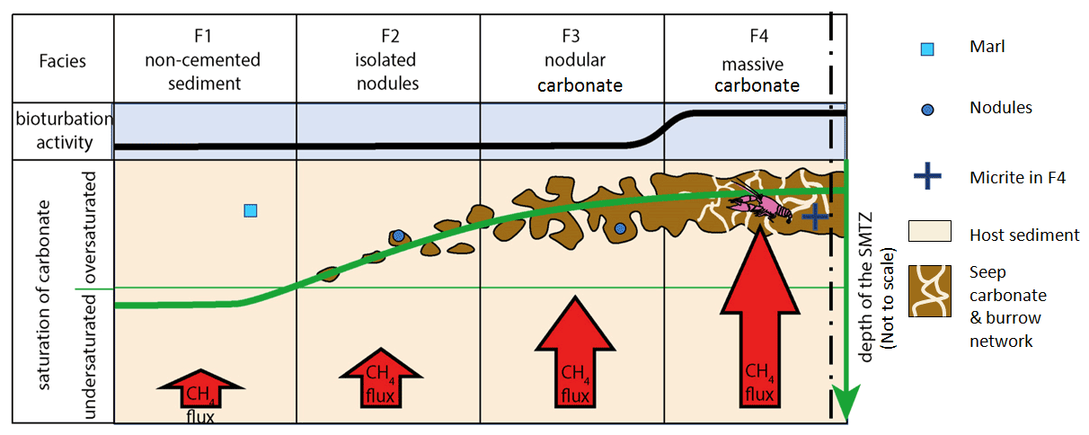
Figure 14Change in depth of the sulfate–methane transition zone (SMTZ) and seep carbonates (brown) from host sediment towards the pseudobioherm; the vertical dashed line marks the axis of the pseudobioherm; geometric symbols refer to the isotope data shown in Fig. 13a; the decapod crustacean symbolizes the burrowers responsible for the gas-focusing burrow network. (Not to scale.)
5.4.2 Facies 4
Carbon isotope data of the Phase-3 burrow infill indicates that the main silicification surface separates AOM-influenced early diagenetic cement from late diagenetic saddle dolomite as the prominent mineral. Anaerobic oxidation of methane can only occur if sulfate is available at a seep site and only within the first few meters below the seafloor at the deepest. The high temperatures required for saddle dolomite precipitation, however, imply that late diagenesis took place at depths largely exceeding 1 km, more likely 2 km assuming geothermal gradients of 30–40 ∘C km−1. In F4, the early, AOM-dominated diagenesis prevailed, whereas the late diagenetic phase only affected Phase-3 burrows. The F4 fabric records the interplay between sedimentation, bioturbation, and early diagenesis. Sedimentation at the seep site must have been identical to that recorded by background Facies 1 (F1), as hemipelagic settling and current deposition acted on a larger scale than the 10 m diameter of the pseudobioherm. Homogenization by bioturbation was the first process that modified the surface sediment, followed by very early cementation that started stiffening the deposits. Bioturbation phases 2 and 3 occurred after enough seep carbonate had been precipitated to allow burrows to remain open and be preserved (e.g., Wetzel and Uchman, 1998). In turn, the open burrows guided upward methane migration and promoted AOM and further gradual cementation around the burrows (Wetzel, 2013). Excluding the effects of silicification, the cement infill of Phase-3 burrows and their host sediment is quite simple: AOM-related carbonate precipitation in the SMTZ is expressed by diagenetic micrite within the pores of homogenized “depositional” micrite, by microspar crystals in the pores of pellet grainstone and in the first 0.1–0.5 mm off the burrow walls (BMSpar–CMSpar), and by spar-sized crystals (Spar-1) in the remaining free space of the lumen. The radiaxial sets of gray carbonate crystals that occasionally terminate the sequence of cements (RAx) may represent recrystallized equivalents to the aragonite fans described by Blouet et al. (2017) in the Panoche Hills (CA, USA) or by Peckmann et al. (1999) from Beauvoisin. Calcite crystals continuing across the BMSpar–CMSpar contacts indicate that the brown color of the former simply reflects the inclusion of the filamentous bushes into the growing microspar. These bushes are reminiscent of the dumbbell-shaped crystal aggregates reported by Peckmann et al. (1999) from the Miocene seep carbonates of Marmorito (Italy), and they are most likely filamentous, bush-shaped microbial colonies that grew over free surfaces of micrite pheno-intraclasts or pellets at burrow walls. The presence or absence of geopetal sediment in the burrows simply reflects the capacity of a burrow segment to trap pellets avalanching from above. Pellets could fall down due to biological activity above or bottom currents inducing circulation within burrows. The variability of 13C depletion of micrite (nodules and pheno-intraclasts) reflects variations in the amount of marine carbonate mixed with the AOM-derived cement. In multiphase samples such as pellet grainstone containing AOM-derived cement, the variability may result from varying amounts of pellets derived from micrite with a variable isotope signature and cement (Figs. 8d, 10c). At seep sites, the SMTZ crops out at the seafloor (Paull and Ussler, 2008). In the Aurel pseudobioherm, the centimeter-scale geometry of the SMTZ was most likely complex, with pervasive downward digitations following the open burrow network that provided a connection to the sulfate-bearing open water. In addition to this complex geometry, tube ventilation by seawater is known to be induced by bottom currents such as tidal currents (“passive ventilation”: Wetzel, 2014; Gingras and Wonneveld, 2015; Rodriguez-Tovar et al., 2019) and by the burrowing organism itself (“active ventilation”). Active ventilation has been shown to be used by decapod crustaceans to promote microbial growth on burrow walls (Savrda, 2007). The microbial colonies of BMSpar may result from one or the other type of ventilation. The key information provided by late diagenesis about the vertical growth of the pseudobioherm is that the tube network constituted by burrow lumina remained open long after the pseudobioherm was buried, at least as long as the pseudobioherm was growing. Silica diagenesis occurred in two phases: in the first one, botryoidal chalcedony precipitated locally above a first succession of AOM-related cements that were, in turn, covered by AOM-related sparite Spar-1; the second phase post-dates all AOM-related carbonate precipitation and is coeval with the precipitation of saddle dolomite. Silica is ubiquitous in the host sediment as sponge spicules; thus, it was readily available within and all around the pseudobioherm. Precipitation of AOM-related carbonates followed by silicification and, in turn, precipitation of non-AOM-related carbonates has been reported from Paleozoic–Cenozoic fossil seep carbonates hosted in siliceous microfossil-bearing sediments by Kuechler et al. (2012) and Smrzka et al. (2015). These authors interpret the silicification event to reflect silica dissolution by alkalinity/pH increase during AOM, favoring dissolution of the silica, followed by reprecipitation when AOM ceased (Kuechler et al., 2012) or the zone of main methane flux shifted laterally (Smrzka et al., 2015). The first phase of silica precipitation in Aurel is coeval with AOM and, thus, does not fully match the observations of Kuechler et al. (2012) or Smrzka et al. (2015). However, early silica could have precipitated during temporary, local interruption of AOM by redirection of methane(-bearing fluids) to another of the numerous conduits in the pseudobioherm that was followed by another episode of AOM when the flow was reestablished. The second, more pervasive phase of silicification was coeval with precipitation of saddle dolomite and largely post-dated the demise of AOM. We hypothesize that it corresponds to a specific step of silica diagenesis affecting the sponge-rich interval of the pseudobioherm, perhaps upon entering the opal-CT–quartz transformation window around 55–85 ∘C (Keller and Isaacs, 1985), which overlaps with the lower range of precipitation temperature for saddle dolomite.
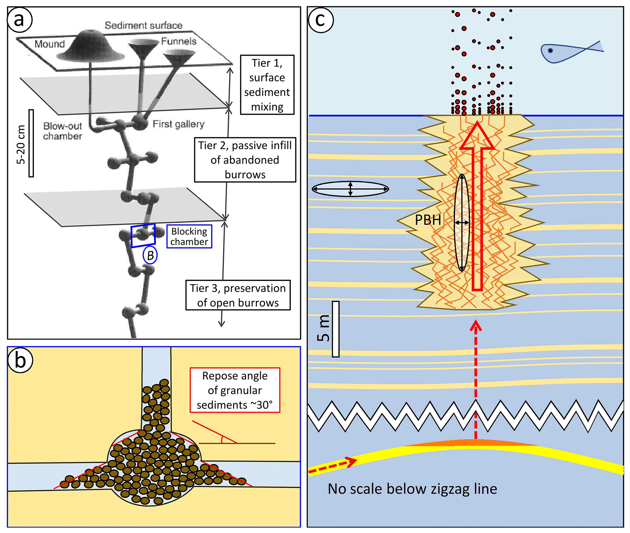
Figure 15Fluid flow in and around the pseudobioherm (PBH). (a) Typical architecture of a recent decapod crustacean burrow (Callianassa truncata, modified after Ziebis et al., 1996); gray surfaces indicate the hypothetical limits between bioturbation tiers 1 and 3 in Aurel (tier 4 below shown interval). The blue frame marks the shallowest chamber acting as trap for sediment shed from above and minimizing further downward sediment transfer. (b) Close-up of trapping chamber; once lateral spill-out from the chamber reaches angle of repose (ca. 30∘, Allen, 1992), additional sediment from above piles up in the shaft and deeper parts of the burrow remain open. (c) Sketch of fluid circulation in and around the Aurel pseudobioherm (PBH) during its formation. The lower part represents the hypothetical deep structure focusing late thermogenic methane into the pseudobioherm; red dashed arrows at depth indicate hypothetical gas migration pathways from a source rock into the structure and further up to the base of the pseudobioherm. The upper part shows the circulation pattern of gas and compaction fluids within the pseudobioherm; orange zigzag lines represent crustacean burrows providing a connected tube network down to the bottom of the pseudobioherm. White ellipses represent permeability tensors in the pseudobioherm and host sediment, with the principal axes of minimum and maximum permeability shown by black arrows; red arrow within the pseudobioherm marks the vertical flow pattern of the gas (-charged fluids), likely with episodic escape of gas at the seafloor (red bubbles in the water column).
5.5 Parameters controlling the stacking pattern
The Aurel seep carbonate body comprises vertically stacked carbonate lenses interfingering with the host marls. The stacking pattern and the uniform character of F4 over the whole thickness of the pseudobioherm indicate overall upward growth keeping pace with deposition. Lateral compensation between successive lenses, due to self-sealing and lateral shift, remains well within the diameter of the carbonate body, except across marker beds A and B where the axis of the pseudobioherm shifted by several meters and stabilized in its new position (Fig. 3). Downward growth, if present, would be restricted to individual lenses a few tens of centimeters thick. Which parameters controlled the vertical growth of the pseudobioherm between the marker beds? The role of Thalassinoides in focusing migration of methane(-charged fluids) has been identified by Wetzel (2013) and later by Wiese et al. (2015), Zwicker et al. (2015), and Blouet et al. (2017). Evidently, in spite of likely overprinting by shallower-tier burrowers, individual Phase-3 burrows remained open until burial reached at least 1 km and provided obvious fluid migration pathways as deep as the burrowing organisms penetrated – likely in the range of 1–3 m, as known for present-day decapod crustaceans (see above). Within tier 1, mainly small-sized organisms (meiofauna < 300 µm) that represent the most efficient “homogenizers” (e.g., Wetzel, 1983) probably avoided the shafts of Thalassinoides so as not to fall into them. Therefore, at least some shafts remained open after burrow abandonment. Burrowers of tier 2, however, could have intersected the upper part of abandoned tier-3 burrows and shed sediment and pellets down the intersected shafts. The estimated average spacing of ∼5 cm between tier-3 burrows implies a tunnel density of about 400 m−2, which is in the mid- to high-density range defined by D'Andrea and DeWitt (2009). As the burrows have a complex branching geometry made of segments with highly variable azimuth and inclination, there is room for many intersections between active and abandoned Phase-3 burrows. Thalassinoides-/Spongeliomorpha-type burrows generally show variable orientation on a centimeter-scale (e.g., Griffis and Suchanek, 1991; Dworschak and de Rodrigues, 1997; Stamhuis et al., 1997; Ziebis et al., 1996), as observed in the Aurel samples (Fig. 15a). The gently inclined segments provide dead ends or traps for sediment avalanching in or entering the burrows; as soon as sediment derived from above reaches a segment dipping less than the angle of repose of granular material, passive fill is hindered and the tunnel network underneath remains open (Fig. 15b). Thus, the geometric arrangement of the tier-3 burrows with subhorizontal segments represents an important factor ensuring that these burrows provided an open tube network over the whole thickness of the pseudobioherm as long as there were organisms active in providing the final opening to the seafloor. Vertical growth is the consequence of such fluid circulation “highways”. Fluids expelled during compaction and buoyant hydrocarbons, once they reached the base of the pseudobioherm, were funneled within the open-burrow network up to domains close to the seafloor where seep carbonate precipitation occurred in the SMTZ. Free gas trapping by any local permeability restriction inside a tube would have initiated the buildup of a continuous gas column below. Its buoyancy could overcome the mechanical resistance of the plug as soon as the height of the column reached about the thickness of the plug (Cathles et al., 2010). The resulting sudden fluid release may have episodically flushed the tube system, contributing to keeping it open. At any time during active seep carbonate growth, the tier-3 burrows provided a connection with the seawater as well as bringing up methane, ensuring both seep carbonate precipitation in the shallow subseafloor and multiple bypass pathways preventing self-sealing. Increasing cementation around the open tubes prevented their collapse. Decapod crustaceans are known to dig deep into the sediment and periodically ventilate their burrow systems with seawater that contains sulfate and to induce cross-stratal fluid flow (e.g., Forster and Graf, 1992; Ziebis et al., 1996). Once initiated, vertical growth became a self-sustaining process. What caused the offset of the seep carbonate column upon crossing marker beds A and B? Event deposition of marker beds that were a few tens of centimeters thick should not have significantly affected burrowers within tiers 2 and 3, as they have the capability to maintain the connection to the seafloor (e.g., Bromley, 1996) and evidently did so, and vertical communication up to the seafloor as previously described must have been reestablished rapidly after the deposition. Because massive calcilutite beds in the pseudobioherm became homogenized by bioturbation at very shallow, 0–10 cm, sediment depths (Wetzel, 1981), it is highly likely that bioturbational mixing broke the continuity of thinner limestone beds by displacing grains into the adjacent marly mud. In contrast, limestone beds thicker than the penetration depth of bioturbational mixing would have their upper few centimeters only mixed with the overlying marls, while a permeable drain would be preserved in the lower part of the bed. Any restriction to fluid flow above the permeable bed likely deflects at least part of incoming methane(-bearing fluid) along the permeable bed, where migration would follow the local gradient at the top of the permeable bed (regional slope combined with local irregularities at the base of the bioturbated, impermeable top-of-bed interval). Upslope migration of hydrocarbon-charged fluids, in turn, shifts the zone of maximum hydrocarbon concentration laterally upslope and also shifts the habitat of burrowers feeding on chemosynthetic microbial communities along their burrow walls and on the seafloor. In summary, the main factor governing seep carbonate stacking in Aurel appears to be the contrast in cubic-meter-scale permeability between the pseudobioherm and its host sediment (Fig. 15c). Sedimentation of the background facies defines a strongly anisotropic permeability tensor on the cubic meter scale, with low vertical permeability due to the fine-grained marls, whereas high lateral permeability occurs before lithification due to the presence of calcilutite limestone beds. At the same scale in the seep carbonate column, the Thalassinoides/Spongeliomorpha tube network results in high vertical permeability (e.g., Cunningham et al., 2012; Gingras et al., 2012), whereas lateral permeability is generally lowered by bioturbational blurring of thin granular limestone beds into the marls. Only granular beds significantly thicker than the mixing depth of near-surface endobenthic organisms remain, to a large proportion, in their original state (e.g., Wheatcroft, 1990; Wetzel, 2009). They can retain sufficient permeability to act as drains, leading to lateral deflection of incoming fluids and lateral shift of the stacking pattern.
The development of the Aurel pseudobioherm, a 15 m thick, 8 m diameter columnar seep carbonate body encased in a > 500 m thick marl succession, was modulated by factors that promoted its vertical growth and limited lateral shift induced by self-sealing. The following two points help explain one key factor that appears to be intense bioturbation by decapod crustaceans:
- a.
The specific morphology of the burrows produced in a deep tier includes low-inclination to horizontal segments that could hinder passive infill by sediment falling from the seafloor or shallower bioturbation tiers, preserving a network of open tubes below.
- b.
The areal density of burrows of ca. 400 burrows m−2, was sufficient to ensure crosscutting between successive generations of burrows, providing a connected network extending deep below the base of the SMTZ and thereby fostering unrestricted vertical fluid percolation through the whole carbonate body due to their high vertical permeability.
The host sediment is dominated by fine-grained marls resulting in very low vertical permeability. In contrast, intervening centimeter-thick laterally continuous calcilutite beds make up to a few percent of the formation and create a relatively high lateral permeability. At the location of the pseudobioherm, these thin beds were mixed with mud through biodeformational bioturbation in the upper 5–10 cm below the seafloor, blocking lateral fluid circulation inside the pseudobioherm and into the host sediment. Conversely, the few >10 cm thick calcilutite beds were not fully homogenized, leading to (possibly upslope) lateral pseudobioherm migration by a few meters along the thicker beds. Thus, the critical factors appear to be the adequate type and abundance of burrows; they foster compaction fluid flow into the pseudobioherm with positive feedback on the development of endobenthic life. The decapod crustacean-promoted focusing of fluid flow into a seepage area could be the antidote to self-sealing and promote sustained vertical growth of seep carbonate bodies. Thus, this type of bioturbation, known to be common at hydrocarbon seep sites, may be a small-scale but critical factor fixing a seepage site at the same point for long spans of time, as has commonly been observed on seismic sections worldwide.
Table A1Results of carbon and oxygen isotope analysis for the 37 studied examples in this paper.

The data are presented in Table A1 in the Appendix.
JPB was responsible for the project design, primary research (field work and laboratory work), data interpretation, manuscript writing, and figure creation. PI was the project founder and contributed to the project supervision, data interpretation, manuscript writing, figure creation, and funding acquisition. SH was responsible for field observations, manuscript revisions, figure and video editing, project adminstration, and team coordination. AW carried out the field observations and manuscript writing, in particular the information on bioturbational structures and processes. AF was the academic supervisor of JPB's related PhD project.
The authors declare that they have no conflict of interest.
Publisher's note: Copernicus Publications remains neutral with regard to jurisdictional claims in published maps and institutional affiliations.
We thank Total Exploration and Production for sponsoring Jean-Philippe Blouet's PhD, for granting permission to publish this research, and for many insightful discussions. In particular, Eric Gaucher is thanked for his constructive comments on the SE France “carbonic province”, and we are grateful to Stéphane Teinturier for preliminary fluid inclusion analysis. The field campaign was made possible by Philippe Artru, who guided us to the outcrops where he conducted his PhD work and first discovered the Aurel pseudobioherm back in the 1960s. Philippe Artru also brought us many original ideas on the regional geology of a basin on which he conducted research for some 10 years of his life. Rolland Oddou, a distinguished collector of septarian concretions from the Terres Noires Formation, generously shared his extensive knowledge of the regional outcrops with us. The personnel of the University of Fribourg are thanked for invaluable advice, in particular Bernard Grobéty for the interpretation of XRD spectra and Silvia Spezzaferri for identification of microfossils. Ivano Aiello and Martin Hovland are acknowledged for the comments that they provided on the PhD thesis chapter version of this article. Maciej Bojanowski (Warsaw, Poland) is thanked for insightful discussion during a field trip sponsored by the International Association of Sedimentology. Thibault Renard and Simon Vuadens are acknowledged for their help in the field in the framework of their master's theses. Thin Section Lab and its personnel (Toul, France) are thanked for providing access to their facilities. Finally, we are grateful to the editor Arjen Stroeven and two anonymous reviewers for their comments and suggestions that significantly helped to improve the paper.
This research has been supported by Total Exploration and Production's Research Department.
This paper was edited by Arjen Stroeven and reviewed by two anonymous referees.
Agirrezabala, L. M., Kiel, S., Blumenberg, M., Schäfer, N., and Reitner, J.: Outcrop analogues of pockmarks and associated methane-seep carbonates: A case study from the Lower Cretaceous (Albian) of the Basque-Cantabrian Basin, western Pyrenees; Palaeogeogr. Palaeocl., 390, 94–115, https://doi.org/10.1016/j.palaeo.2012.11.020, 2013. a, b
Allen, J. R. L.: Principles of physical sedimentology, reprinted (with corrections), Springer US, 272 pp., https://doi.org/10.1007/978-1-4613-2545-1, 1992. a
Artru, P.: Les terres noires du bassin rhodanien (Bajocien supérieur à Oxfordien moyen): stratigraphie, sédimentologie, géochimie-Alpes françaises, Université Claude Bernard-Lyon I, 182 pp., 1972. a, b, c, d
Artru, P. and Gauthier, J.: Etude géochimique d'une séquence des “terres noires”; application au problème de l'écologie de spongiaires constructeurs, B. Soc. Géol. Fr., S7-VIII, 405–412, 10.2113/gssgfbull.S7-VIII.3.405, 1966. a
Baudrimont, A. and Dubois, P.: Un bassin mésogéen du domaine péri-alpin: le Sud-Est de la France, Bulletin Centres de Recherche Exploration-Production Elf Aquitaine, 1, 261–308, 1977. a
Bayon, G., Henderson, G. M., and Bohn, M.: U–Th stratigraphy of a cold seep carbonate crust, Chem. Geol., 260, 47–56, 2009. a
Berndt, C.: Focused fluid flow in passive continental margins, Philos. T. R. Soc. A, 363, 2855–2871, 2005. a
Blouet, J. P., Imbert, P., and Foubert, A.: Mechanisms of biogenic gas migration revealed by seep carbonate paragenesis, Panoche Hills, California, AAPG Bull., 101, 1309–1340, 2017. a, b
Blouet, J. P., Arndt, S., Imbert, P., and Regnier, P.: Are seep carbonates quantitative proxies of CH4 leakage? Modeling the influence of sulfate reduction and anaerobic oxidation of methane on pH and carbonate precipitation, Chem. Geol., 577, 120254, https://doi.org/10.1016/j.chemgeo.2021.120254, 2021a. a
Blouet, J. P., Imbert, P., Foubert, A., Ho, S., and Dupont, G.: From seep carbonates down to petroleum systems: An outcrop study from the southeastern France Basin, AAPG Bull., 105, 1033–1064, 2021b. a
Blouet, J. P., Wetzel, A., and Ho, S.: Fluid conduits formed along burrows of giant bivalves at a methane seep site, southern Taiwan, Mar. Petrol. Geol., 105123, https://doi.org/10.1016/j.marpetgeo.2021.105123, 2021c. a
Boetius, A., Ravenschlag, K., Schubert, C. J., Rickert, D., Widdel, F., Gieseke, A., Amann, R., Jørgensen, B. B., Witte, U., and Pfannkuche, O.: A marine microbial consortium apparently mediating anaerobic oxidation of methane, Nature, 407, 623–626, https://doi.org/10.1038/35036572, 2000. a
Botz, R., Pokojski, H. D., Schmitt, M., and Thomm, M.: Carbon isotope fractionation during bacterial methanogenesis by CO2 reduction, Org. Geochem., 25, 255–262, 1996. a
Boudreau, B. P.: The physics of bubbles in surficial, soft, cohesive sediments, Mar. Petrol. Geol., 38, 1–18, 2012. a, b
Bromley, R. G.: Trace fossils; biology, taphonomy and applications, Chapman and Hall, London, UK, 1996. a
Bunz, S., Mienert, J., and Berndt, C.: Geological controls on the Storegga gas-hydrate system of the mid-Norwegian continental margin, Earth Planet. Sc. Lett., 209, 291–307, 2003. a
Campbell, K. A.: Hydrocarbon seep and hydrothermal vent paleoenvironments and paleontology: Past developments and future research directions, Palaeogeogr. Palaeocl., 232, 362–407, 2006. a, b, c
Casenave, V., Gay, A., and Imbert, P.: Spider structures: records of fluid venting from methane hydrates on the Congo continental slope. Les structures en araignée: enregistrement d'échappements de fluide provenant des hydrates de méthane sur la pente continentale du Congo, B. Soc. Géol. Fr., 188, 27, https://doi.org/10.1051/bsgf/2017189, 2017. a
Cathles, L. M., Su, Z., and Chen, D.: The physics of gas chimney and pockmark formation, with implications for assessment of seafloor hazards and gas sequestration, Mar. Petrol. Geol., 27, 82–91, 2010. a
COPEFA: Rapport géologique de fin de sondage, Aurel 1, log détaillé, Bureau de Recherches Geologiques et Minieres, Orléans, France, p. 1, 1967. a, b
Cunningham, K. J., Sukop, M. C., and Curran, H. A.: Carbonate aquifers, in: Trace Fossils as Indicators of Sedimentary Environments, edited by: Knaust, D. and Bromley, R. G., Developments in Sedimentology, 64, 869–896, Elsevier, Amsterdam, 2012. a, b, c
D'Andrea, A. F. and DeWitt, T. H.: Geochemical ecosystem engineering by the mud shrimp Upogebia pugettensis (Crustacea: Thalassinidae) in Yaquina Bay, Oregon: Density-dependent effects on organic matter remineralization and nutrient cycling, Limnol. Oceanogr., 54, 1911–1932, 2009. a
De Boever, E., Huysmans, M., Muchez, P., Dimitrov, L., and Swennen, R.: Controlling factors on the morphology and spatial distribution of methane-related tubular concretions–Case study of an Early Eocene seep system, Mar. Petrol. Geol., 26, 1580–1591, 2009. a
Debrand-Passard, S., Courbouleix, S., and Lienhardt, M.-J.: Synthèse géologique du Sud-Est de la France, Voulme 2, Atlas, Éditions du Bureau de recherches géologiques et minières, Orléans, France, Vol. 125, 28 pp., 64 maps, 1984. a, b
Dupré, S., Loubrieu, B., Pierre, C., Scalabrin, C., Guérin, C., Ehrhold, A., Ogor, A., Gautier, E., Ruffine, L., Biville, R., Saout, J., Breton, C., Floodpage, J., and Lescanne, M.: The Aquitaine Shelf edge (Bay of Biscay): A primary outlet for microbial methane release, Geophys. Res. Lett., 47, e2019GL084561, https://doi.org/10.1029/2019GL084561, 2020. a
Dworschak, P. C. and de Rodrigues, S. A.: A modern analogue for the trace fossil Gyrolithes: burrows of the thalassinidean shrimp Axianassa australis, Lethaia, 30, 41–52, 1997. a
Flandrin, J.: Carte géologique de la France, Die, scale 1 50 000, BRGM Editions, Orléans, France, 1974. a, b, c
Forster, S. and Graf, G.: Continuously measured changes in redox potential influenced by oxygen penetrating from burrows of Callianassa subterranena, Hydrobiologia, 235, 527–532, 1992. a
Fuex, A. N.: The use of stable carbon isotopes in hydrocarbon exploration, J. Geochem. Explor., 7, 155–188, 1977. a, b
Gaillard, C., Bourseau, J.-P., Boudeulle, M., Pailleret, P., Rio, M., and Roux, M.: Les pseudo-biohermes de Beauvoisin (Drôme): un site hydrothermal sur la marge téthysienne à l'Oxfordien?, B. Soc. Géol. Fr., 1, 69–78, 1985. a
Gaillard, C., Rio, M., Rolin, Y., and Roux, M.: Fossil chemosynthetic communities related to vents or seeps in sedimentary basins: the pseudobioherms of southeastern France compared to other world examples, Palaios, 7, 451–465, https://doi.org/10.2307/3514829, 1992. a
Gay, A., Lopez, M., Cochonat, P., Sultan, N., Cauquil, E., and Brigaud, F.: Sinuous pockmark belt as indicator of a shallow buried turbiditic channel on the lower slope of the Congo Basin, West African Margin, Geol. Soc. Lond. Spec. Publ., 216, 173–189, https://doi.org/10.1144/GSL.SP.2003.216.01.12, 2003. a
Gay, A., Lopez, M., Potdevin, J. L., Vidal, V., Varas, G., Favier, A., and Tribovillard, N.: 3D morphology and timing of the giant fossil pockmark of Beauvoisin, SE Basin of France, J. Geol. Soc., 176, 61–77, 2019. a, b
Gay, A., Favier, A., Potdevin, J. L., Lopez, M., Bosch, D., Tribovillard, N., Ventalon, S., Cavailhes, T., Neumaier, M., Revillon, S., Travé, A., Bruguier, O., Delmas, D., Delmas, D., and Nevado, C.: Poly-phased fluid flow in the giant fossil pockmark of Beauvoisin, SE basin of France, BSGF-Earth Sciences Bulletin, 191, 35, https://doi.org/10.1051/bsgf/2020036, 2020. a, b, c, d, e, f
Gingras, M. K. and Zonneveld, J.-P.: Tubular tidalites: A biogenic sedimentary structure indicative of tidally influenced sedimentation, J. Sediment. Res., 85, 845–854, 2015. a
Gingras, M. K., Baniak, G., Gordon, J., Hosikovski, J., Konhauser, K. O., La Croix, A., Lemiski, R., Mendoza, C., Pemberton, S. G., Polo, C., and Zonneveld, J.-P.: Porosity and permeability in bioturbated sediments, in: Developments in Sedimentology, edited by: Knaust, D. and Bromley, R. G., Elsevier, Vol. 64, 837–868, https://doi.org/10.1016/B978-0-444-53813-0.00027-7, 2012. a
Greinert, J., Bohrmann, G., and Elvert, M.: Stromatolitic fabric of authigenic carbonate crusts: result of anaerobic methane oxidation at cold seeps in 4,850 m water depth, Int. J. Earth Sci., 91, 698–711, 2002. a
Griffis, R. B. and Suchanek, T. H.: A model of burrow architecture and trophic modes in thalassinidean shrimp (Decapoda: Thalassinidea), Mar. Ecol.-Prog. Ser., 79, 171–183, 1991. a
Haas, A., Peckmann, J., Elvert, M., Sahling, H., and Bohrmann, G.: Patterns of carbonate authigenesis at the Kouilou pockmarks on the Congo deep-sea fan, Mar. Geol., 268, 129–136, 2010. a
Heggland, R.: Gas seepage as an indicator of deeper prospective reservoirs. A study based on exploration 3D seismic data, Mar. Petrol. Geol., 15, 1–9, 1998. a
Ho, S., Cartwright, J. A., and Imbert, P.: Vertical evolution of fluid venting structures in relation to gas flux, in the Neogene-Quaternary of the Lower Congo Basin, Offshore Angola, Mar. Geol., 332, 40–55, 2012. a
Ho, S., Carruthers, D., and Imbert, P.: Insights into the permeability of polygonal faults from their intersection geometries with Linear Chimneys: a case study from the Lower Congo Basin, Carnets Geol., 16, 17–26, https://doi.org/10.4267/2042/58718, 2016. a, b
Ho, S., Hovland, M., Blouet, J.-P., Wetzel, A., Imbert, P., and Carruthers, D.: Formation of linear planform chimneys controlled by preferential hydrocarbon leakage and anisotropic stresses in faulted fine-grained sediments, offshore Angola, Solid Earth, 9, 1437–1468, https://doi.org/10.5194/se-9-1437-2018, 2018a. a
Ho, S., Imbert, P., Hovland, M., Wetzel, A., Blouet, J.-P., and Carruthers, D.: Downslope-shifting pockmarks: interplay between hydrocarbon leakage, sedimentations, currents and slope's topography, Int. J. Earth Sci., 107, 2907–2929, https://doi.org/10.1007/s00531-018-1635-5, 2018b. a
Hovland, M.: Pockmarks and the recent geology of the central section of the Norwegian Trench, Mar. Geol., 47, 283–301, 1982. a
Hovland, M.: On the self-sealing nature of marine seeps, Cont. Shelf Res., 22, 2387–2394, https://doi.org/10.1016/S0278-4343(02)00063-8, 2002. a
Hovland, M., Talbot, M., Olaussen, S., and Aasberg, L.: Recently formed methane-derived carbonates from the North Sea floor, Petroleum Geochemistry, in: Exploration of the Norwegian Shelf, Springer, 263–266, https://doi.org/10.1007/978-94-009-4199-1_22, 1985. a
Hovland, M. and Judd, A.: Seabed Pockmark and Seepage, Graham and Trotman, Salisbury, United Kingdom, 293 pp., 1988. a, b
Hovland, M., Croker, P. F., and Martin, M.: Fault-associated seabed mounds (carbonate knolls?) off western Ireland and north-west Australia, Mar. Petrol. Geol., 11, 232–246, https://doi.org/10.1016/0264-8172(94)90099-X, 1994. a
Hustoft, S., Bunz, S., and Mienert, J.: Three‐dimensional seismic analysis of the morphology and spatial distribution of chimneys beneath the Nyegga pockmark field, offshore mid-Norway, Basin Res., 22, 465–480, 2010. a
IFP: Le bassin du Sud-Est, son exploration et ses perspectives pétrolières, v. fascicule 2, Réf 29 881-2, 213 pp., 1982a. a
IFP: Le bassin du Sud-Est, son exploration et ses perspectives pétrolières, v. fascicule 1, Réf 29 881-1, 73 pp., IFP, Rueil-Malmaison, 1982b. a
IFP: Le bassin du Sud-Est, son exploration et ses perspectives pétrolières, v. fascicule 3, Réf 29 881-3, 6 pp., IFP, Rueil-Malmaison, 1982c. a
Jensen, P., Aagaard, I., Burke Jr., R. A., Dando, P. R., Jørgensen, N. O., Kuijpers, A., Laier, T., O'Hara, S. C. M., and Schmaljohann, R.: “Bubbling reefs” in the Kattegat: submarine landscapes of carbonate-cemented rocks support a diverse ecosystem at methane seeps, Mar. Ecol.-Prog. Ser., 83, 103–112, 1992. a
Jourabchi, P., Van Cappellen, P., and Regnier, P.: Quantitative interpretation of pH distributions in aquatic sediments: A reaction-transport modeling approach, Am. J. Sci., 305, 919–956, 2005. a
Judd, A. and Hovland, M.: Seabed fluid flow: the impact on geology, biology and the marine environment, Cambridge University Press, Cambridge, UK, 2007. a
Katsman, R., Ostrovsky, I., and Makovsky, Y.: Methane bubble growth in fine-grained muddy aquatic sediment: insight from modeling, Earth Planet. Sc. Lett., 377, 336–346, 2013. a
Kauffman, E. G., Arthur, M. A., Howe, B., and Scholle, P. A.: Widespread venting of methane-rich fluids in Late Cretaceous (Campanian) submarine springs (Tepee Buttes), Western Interior seaway, USA, Geology, 24, 799–802, 1996. a, b
Keller, M. A. and Isaacs, C. M.: An evaluation of temperature scales for silica diagenesis in diatomaceous sequences including a new approach based on the Miocene Monterey Formation, California, Geo-Mar. Lett., 5, 31–35, 1985. a
Kiel, S. (Ed.): The Vent and Seep Biota: Aspects from Microbes to Ecosystems, in: Topics in Geobiology, Vol. 33, Springer Science and Business Media, 487 pp., 2010. a, b
Kiel, S., Campbell, K. A., and Gaillard, C.: New and little known mollusks from ancient chemosynthetic environments, Zootaxa, 2390, 26–48, 2010. a
Knaust, D.: Atlas of trace fossils in well core: appearance, taxonomy and interpretation, Springer, Cham, Switzerland, https://doi.org/10.1007/978-3-319-49837-9, 2017. a
Krause, F. F., Clark, J., Sayegh, S. G., and Perez, R. J.: Tube worm fossils or relic methane expulsing conduits?, Palaios, 24, 41–50, 2009. a
Kuechler, R. R., Birgel, D., Kiel, S., Freiwald, A., Goedert, J. L., Thiel, V., and Peckmann, J.: Miocene methane‐derived carbonates from southwestern Washington, USA and a model for silicification at seeps, Lethaia, 45, 259–273, 2012. a, b, c
Lemoine, M., Bas, T., Arnaud-Vanneau, A., Arnaud, H., Dumont, T., Gidon, M., Bourbon, M., de Graciansky, P.-C., Rudkiewicz, J.-L., and Mégard-Galli, J.: The continental margin of the Mesozoic Tethys in the Western Alps, Mar. Petrol. Geol., 3, 179–199, https://doi.org/10.1016/0264-8172(86)90044-9, 1986. a
Lemoine, M., de Graciansky, P. C., and Tricart, P.: De l'océan à la chaîne de montagnes: tectonique des plaques dans les Alpes, Gordon and Breach Science Publishers, London, UK, 207 pp., 2000. a
Liebetrau, V., Augustin, N., Kutterolf, S., Schmidt, M., Eisenhauer, A., Garbe-Schönberg, D., and Weinrebe, W.: Cold-seep-driven carbonate deposits at the Central American forearc: contrasting evolution and timing in escarpment and mound settings, Int. Jo. Earth Sci., 103, 1845–1872, 2014. a
Loseth, H., Gading, M., and Wensaas, L.: Hydrocarbon leakage interpreted on seismic data, Mar. Petrol. Geol., 26, 1304–1319, 2009. a
Loseth, H., Wensaas, L., Arntsen, B., Hanken, N.-M., Basire, C., and Graue, K.: 1000 m long gas blow-out pipes, Mar. Petrol. Geol., 28, 1047–1060, 2011. a, b
Ligtenberg, J.: Unravelling the petroleum system by enhancing fluid migration paths in seismic data using a neural network-based pattern recognition technique, Geofluids, 3, 255–261, 2003. a
Mascle, A. and Vially, R.: The petroleum systems of the Southeast Basin and Gulf of Lion (France), Geol. Soc. Lond. Spec. Publ., 156, 121–140, https://doi.org/10.1144/GSL.SP.1999.156.01.08, 1999. a
Masini, E., Manatschal, G., and Mohn, G.: The Alpine Tethys rifted margins: Reconciling old and new ideas to understand the stratigraphic architecture of magma‐poor rifted margins, Sedimentology, 60, 174–196, https://doi.org/10.1111/sed.12017, 2013. a
Mazzini, A., Duranti, D., Jonk, R., Parnell, J., Cronin, B., Hurst, A., and Quine, M.: Palaeo-carbonate seep structures above an oil reservoir, Gryphon Field, Tertiary, North Sea, Geo-Mar. Lett., 23, 323–339, https://doi.org/10.1007/s00367-003-0145-y, 2003. a
Meesook, A., Sha, J., Yamee, C., and Saengsrichan, W.: Faunal associations, paleoecology and paleoenvironment of marine Jurassic rocks in the Mae Sot, PhopPhra, and Umphang areas, western Thailand, Sci. China Ser. D, 52, 2001–2023, 2009. a
Milkov, A. V. and Etiope, G.: Revised genetic diagrams for natural gases based on a global dataset of > 20,000 samples, Org. Geochem., 125, 109–120, 2018. a
Montenat, C. and Patillet, J.: Septarias à hydrocarbures dans les “Terres noires” d'Orpierre (?Hautes-Alpes), C.R. Acad. Sci., 266, 1–3, 1968. a
Mourgues, R., Bureau, D., Bodet, L., Gay, A., and Gressier, J. B.: Formation of conical fractures in sedimentary basins: Experiments involving pore fluids and implications for sandstone intrusion mechanisms, Earth Planet. Sc. Lett., 313, 67–78, 2012. a
Naudts, L., Greinert, J., Artemov, Y., Beaubien, S. E., Borowski, C., and De Batist, M.: Anomalous sea-floor backscatter patterns in methane venting areas, Dnepr paleo-delta, NW Black Sea, Mar. Geol., 251, 253–267, 2008. a
Negra, M. H., Zagrarni, M. F., Hanini, A., and Strasser, A.: The filament event near the Cenomanian-Turonian boundary in Tunisia: filament origin and environmental signification, B. Soc. Géol. Fr., 182, 507–519, 2011. a
Oddou, R.: Les nodules baritiques, géodes de Provence, Les Éditions du Piat, Le Puy, France, 100 pp., 2004. a
Orgeval, M. and Zimmermann, M.: Perspectives pétrolières de la zone subalpine, Bassin Méridional, Bureau de Recherches du Pétrole, Mission du Couloir Rhodanien, Bureau de Recherches Geologiques et Minieres, Orléans, France, 145 pp., 1957. a
Orcutt, B. N., Joye, S. B., Kleindienst, S., Knittel, K., Ramette, A., Reitz, A., Samarkin, V., Treude, T., and Boetius, A.: Impact of natural oil and higher hydrocarbons on microbial diversity, distribution, and activity in Gulf of Mexico cold-seep sediments, Deep-Sea Res. Pt. II, 57, 2008–2021, https://doi.org/10.1016/j.dsr2.2010.05.014, 2010. a
Paull, C. K. and Ussler III, W.: Re-evaluating the significance of seafloor accumulations of methane-derived carbonates: seepage or erosion indicators, in: Proceedings of the 6th International Conference on Gas Hydrates (ICGH 2008), Vancouver, British Columbia, Canada, July 2008, 6–10, 2008. a, b
Peckmann, J., Goedert, J. L., Thiel, V., Michaelis, W., and Reitner, J.: A comprehensive approach to the study of methane‐seep deposits from the Lincoln Creek Formation, western Washington State, USA, Sedimentology, 49, 855–873, 2002. a
Peckmann, J., Goedert, J. L., Heinrichs, T., Hoefs, J., and Reitner, J.: The Late Eocene “Whiskey Creek” methane-seep deposit (western Washington State), Facies, 48, 241–253, 2003. a
Peckmann, J. and Thiel, V.: Carbon cycling at ancient methane–seeps, Chemical Geology, 205, 443–467, 2004. a, b
Peckmann, J., Thiel, V., Michaelis, W., Clari, P., Gaillard, C., Martire, L., and Reitner, J.: Cold seep deposits of Beauvoisin (Oxfordian; southeastern France) and Marmorito (Miocene; northern Italy): microbially induced authigenic carbonates, Int. J. Earth Sci., 88, 60–75, 1999. a, b, c
Pellenard, P., Tramoy, R., Pucéat, E., Huret, E., Martinez, M., Bruneau, L., and Thierry, J.: Carbon cycle and sea-water palaeotemperature evolution at the Middle–Late Jurassic transition, eastern Paris Basin (France), Mar. Petrol. Geol., 53, 30–43, 2014.
Pemberton, G. S. and Buckley, D. E.: Supershrimp: Deep bioturbation in the Strait of Canso, Nova Scotia, Science, 192, 790–791, 1976. a
Petersen, C. J., Bunz, S., Hustoft, S., Mienert, J., and Klaeschen, D.: High-resolution P-Cable 3D seismic imaging of gas chimney structures in gas hydrated sediments of an Arctic sediment drift, Mar. Petrol. Geol., 27, 1981–1994, 2010. a
Plaza-Faverola, A., Bunz, S., and Mienert, J.: Repeated fluid expulsion through sub-seabed chimneys offshore Norway in response to glacial cycles, Earth Planet. Sci. Lett., 305, 297–308, https://doi.org/10.1016/j.epsl.2011.03.001, 2011. a, b
Regnier, P., Dale, A. W., Arndt, S., LaRowe, D. E., Mogollón, J., and Van Cappellen, P.: Quantitative analysis of anaerobic oxidation of methane (AOM) in marine sediments: a modeling perspective, Earth-Sci. Rev., 106, 105–130, 2011. a
Rodriguez-Tovar, F. J., Mayoral, E., Santos, A., Dorador, X., and Wetzel, A.: Crowded tubular tidalites in Miocene shelf sandstones of southern Iberia, Palaeogeogr. Palaeocl., 521, 1–9, 2019. a
Rolin, Y.: Gisements fossilifères liés à des sources sous-marines dans le bassin des terres noires: le site oxfordien de Beauvoisin (Drôme, Chaînes subalpines méridionales): Comparaison avec les sites océaniques actuels, PhD thesis, University of Lyon I (France), 141 pp., 1987. a, b
Rolin, Y., Gaillard, C., and Roux, M.: Ecologie des pseudobiohermes des Terres Noires jurassiques liés à paléo-sources sous-marines. Le site oxfordien de Beauvoisin (Drôme, Bassin du Sud-Est, France), Palaeogeogr. Palaeocl., 80, 79–105, https://doi.org/10.1016/0031-0182(90)90123-O, 1990. a
Roure, F., Brun, J.-P., Colletta, B., and Van Den Driessche, J.: Geometry and kinematics of extensional structures in the Alpine foreland basin of southeastern France, J. Struct. Geol., 14, 503–519, https://doi.org/10.1016/0191-8141(92)90153-N, 1992. a, b
Sander, M. V. and Black, J. E.: Crystallization and recrystallization of growth-zoned vein quartz crystals from epithermal systems; implications for fluid inclusion studies, Econ. Geol., 83, 1052–1060, 1988. a
Sarnthein, M.: Stratigraphic contamination by vertical bioturbation in Holocene shelf sediments, in: 24th International Geological Congress, Section 6, 432–436, 24th International geological Congress, Montréal, Canada, 1972. a
Savrda, C. E.: Trace fossils and marine benthic oxygenation, in: Trace Fossils: Concepts, Problems, Prospects, edited by: Miller III, W., Elsevier, Amsterdam, 149–158, 2007. a
Schäfer, W.: Wirkungen der Benthos Organismen auf den jungen Schichtverband, Senkenbergiana Lethaia, 37, 183–263, 1956. a
Smrzka, D., Kraemer, S. M., Zwicker, J., Birgel, D., Fischer, D.,Kasten, S., Goedert, J. L., and Peckmann, J.: Constraining silica diagenesis in methane-seep deposits, Palaeogeogr. Palaeocl., 420, 13–26, 2015. a, b, c
Spötl, C. and Pitman, J. K.: Saddle (baroque) dolomite in carbonates and sandstones: a reappraisal of a burial-diagenetic concept, in: Carbonate Cementation in Sandstones: Distribution Patterns and Geochemical Evolution, Int. As. Sed. Spec. Publ., 26, 437–460, 1998. a, b
Stamhuis, E. J., Schreurs, C. E., and Videler, J. J.: Burrow architecture and turbative activity of the thalassinid shrimp Callianassa subterranea from the central North Sea, Mar. Ecol.-Prog. Ser., 151, 155–163, 1997. a
Suess, E., Carson, B., Ritger, S. D., Moore, J. C., Jones, M. L., Kulm, L. D., and Cochrane, G. R.: Biological communities at vent sites along the subduction zone off Oregon, Bulletin of the Biological Society of Washington, 6, 475–484, https://doi.org/10.1016/0198-0149(88)90079-9, 1985. a
Wannesson, J. and Bessereau, G.: Institut Français du Pétrole regional report, Bassin du Sud-Est, Rueil-Malmaison, France, 159 pp., 1999. a, b, c, d, e
Wetzel, A.: Ökologische und stratigraphische Bedeutung biogener Gefüge in quartären Sedimenten am NW-afrikanischen Kontinentalrand, “Meteor” Forschungs-Ergebnisse, Reihe C, 34, 1–47, 1981. a
Wetzel, A.: Biogenic sedimentary structures in a modern upwelling region: NW African continental margin, in: Coastal Upwelling and Its Sediment Record, Part B, Sedimentary Records of Ancient Coastal Upwelling, edited by: Thiede, J. and Suess, E., Plenum, New York, 123–144, 1983. a, b, c
Wetzel, A.: Ecologic interpretation of deep-sea trace fossil communities, Palaeogeogr. Palaeocl., 85, 47–69, 1991. a
Wetzel, A.: The preservation potential of ash layers in the deep-sea: the example of the 1991-Pinatubo ash in the South China Sea, Sedimentology, 56, 1992–2009, 2009. a
Wetzel, A.: Formation of methane-related authigenic carbonates within the bioturbated zone – An example from the upwelling area off Vietnam, Palaeogeogr. Palaeocl., 386, 23–33, 2013. a, b
Wetzel, A., Carmona, N., and Ponce, J.: Tidal signature recorded in burrow fill, Sedimentology, 61, 1198–1210, 2014. a
Wetzel, A. and Uchman, A.: Biogenic sedimentary structures in mudstones – an overview, in: Shales and Mudstones I., edited by: Schieber, J., Zimmerle, W., and Sethi, P., Schweizerbart, Stuttgart, 351–369, 1998. a, b, c
Wheatcroft, R. A.: Preservation potential of sedimentary event layers, Geology, 18, 843–845, 1990. a
Whiticar, M. J.: Carbon and hydrogen isotope systematics of bacterial formation and oxidation of methane, Chem. Geol., 161, 291–314, 1999. a
Wiese, F., Kiel, S., Pack, A., Walliser, E. O., and Agirrezabala, L. M.: The beast burrowed, the fluid followed–Crustacean burrows as methane conduits, Mar. Petrol. Geol., 66, 631–640, 2015. a
Ziebis, W., Forster, S., Huettel, M., and Joergensen, B. B.: Complex burrows of the mud shrimp Callianassa truncata and their geochemical impact in the sea bed, Nature, 382, 619–622, 1996. a, b
Zwicker, J., Smrzka, D., Gier, S., Goedert, J. L., and Peckmann, J.: Mineralized conduits are part of the uppermost plumbing system of Oligocene methane-seep deposits, Washington State (USA), Mar. Petrol. Geol., 66, 616–630, 2015. a, b
Zwicker, J., Smrzka, D., Himmler, T., Monien, P., Gier, S., Goedert, J., and Peckmann, J.: Rare earth elements as tracers for microbial activity and early diagenesis: A new perspective from carbonate cements of ancient methane-seep deposits, Chem. Geol., 501, 77–85, https://doi.org/10.1016/j.chemgeo.2018.10.010, 2018. a