the Creative Commons Attribution 4.0 License.
the Creative Commons Attribution 4.0 License.
 | 03 Mar 2023
Analogue modelling of the inversion of multiple extensional basins in foreland fold-and-thrust belts
Nicolás Molnar
Susanne Buiter
The presence of pre-existing rheological heterogeneities in the lithosphere plays a significant role during subsequent stages of deformation in essentially every geological process. Extensional basins located in foreland fold-and-thrust belts will alter the spatio-temporal evolution of its associated orogen. It remains unclear how far horizontal stresses can act and reactivate extensional structures due to their intrinsic irregular patterns of deformation deflection and localisation. Overprinting events and relative dating uncertainties in the geological record make it difficult to interpret how stresses were transferred across a heterogeneous crust. Here we examine the inversion of extensional basins in foreland fold-and-thrust belts by using three-dimensional analogue experiments that simulate first an extensional stage, followed by a shortening stage. Our results show how extensional basins proximal to the orogenic front effectively localise deformation in the shape of thrusts and prevent stress transfer beyond their location. Basins that are located at large distances from the orogenic front also show evidence of mild inversion at early stages but are characterised only by basin infill contraction and uplift. When multiple extensional basins are present, the degree and type of inversion will depend primarily on their relative location and distance to the orogenic front. Here we also prove that the presence of additional extensional features in the vicinity of a basin can be a first-order controlling factor in their overall reactivation history. We share additional insights of how a fold-and-thrust belt evolves once the extensional basins have been incorporated by the advancing wedge, and we provide comparisons with natural examples that shed light on some still unanswered questions related to the process of basin inversion in orogenic belts.
- Article
(14177 KB) - Full-text XML
- BibTeX
- EndNote


The process in which compressional stresses induce basin uplift and reverse reactivation of normal faults in former extensional basins is commonly referred to as positive basin inversion (e.g. Bally, 1984; Cooper and Williams, 1989; Jackson, 1980; Sibson, 1990; Ziegler, 1989; Zwaan et al., 2022; Fig. 1a). The degree of inversion can range from mild, which only partly nullifies the previous basin subsidence, to (over-)complete, which brings the former basin floor back to or above its regional equivalent level. Examples of mild inversion can be found in the North Sea (i.e. Nalpas et al., 1995; Scisciani et al., 2019), whereas an example of “over-inversion” can be found in the Permo–Triassic Dorénaz basin that was strongly shortened during formation of the Swiss Alps (Pfiffner, 2009). The incorporation of extensional basins in an orogen will alter the spatio-temporal evolution of that orogen, mainly by localising strain along rheological weaknesses associated with pre-existing faults and/or uncompacted sedimentary infill (Fig. 1a). Here the nature, size, geometry, and rheology of the extensional basins plays a major role.
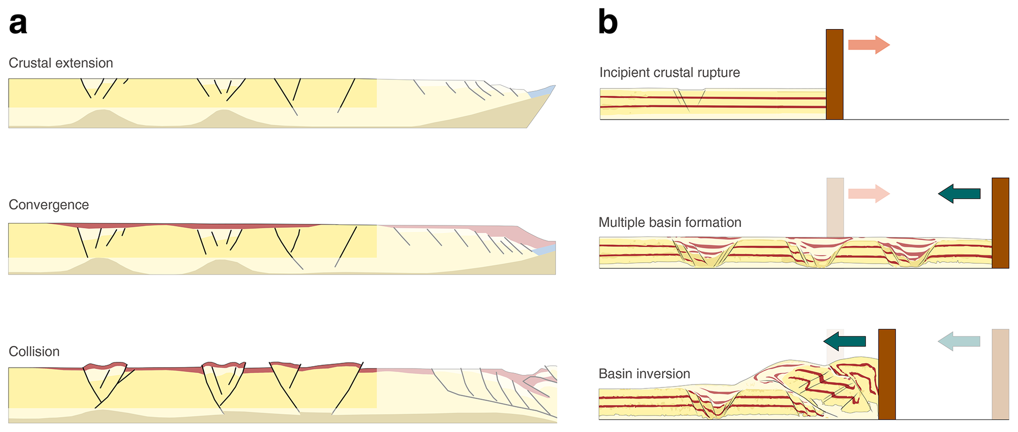
Figure 1(a) Conceptual model of crustal extension and later foreland compressional deformation (redrawn from Ziegler, 1989). (b) Sketch representing the equivalent modelling stages presented in this study.
Relationships between inversion structures in the foreland of orogens, sometimes located up to several hundred kilometres away, and compressional far-field stresses caused by the orogenic fronts have long been identified (Ziegler et al., 1995, 1998). Examples of compressional or transpressional deformation have been shown in the Alpine foreland up to 1300 km north-west of the Alpine thrust front (Ziegler, 1989; Nalpas et al., 1995; Kley, 2018), in the Laramides of North America 600 km to the east of the Cordilleran thrust front (Brewer and Turcotte, 1980; Ziegler, 1989; Cooper and Warren, 2020), and in the foreland of the Variscan and Alpine chains of north-western Africa 800 km to the south of the orogenic front (Ziegler, 1988, 1989; Guiraud and Bosworth, 1997). However, mechanisms of stress transfer across a heterogeneous crust and conditions that facilitate or hinder basin inversion in these settings remain unclear. Transmission of stresses in the lithosphere depends on the degree of interplate coupling (Lacombe and Bellahsen, 2016; Delvaux, 2001) and on the rheological parameters (structural, thermal, and/or compositional) that determine the spatial strength distribution within the lithosphere (Granado and Ruh, 2019; Lacombe and Bellahsen, 2016; Ziegler, 1998). It has been long recognised that areas with major pre-existing extensional faults are prone to early inversion in collision-related intraplate deformation (e.g. Ziegler et al., 1995; Lacombe and Bellahsen, 2016; and references therein), but it remains challenging to accurately describe how far horizontal stresses can act through a heterogeneous crust and the extent to which these pre-existing extensional structures are reactivated (e.g. Bosworth and Tari, 2021).
There is a good understanding of how structural features at the metre to kilometre scale are indicators of basin inversion, such as normal faults that localise thrust ramps or act as stress risers, thrust ramps that cross-cut earlier normal faults, folds, and the uplift of syn-rift strata (e.g. Bonini et al., 2012; Scisciani, 2009; Granado et al., 2017). Nevertheless, when compressional deformation is distributed across larger regions of extended crust, the analysis of multiple overprinted geological events becomes increasingly complex. The complexity lies in discerning between individual structural features and establishing their chronological order, even when there is good availability of sub-surface imaging or well data (Butler and Bond, 2021; Coward, 1994).
In this context, analogue modelling techniques, combined with modern monitoring and visualisation methods, can provide a valuable approach for better understanding mechanisms of basin inversion as they have the advantage of quantifying deformation in time and space. Previous analogue modelling works have provided great insights on the spatio-temporal evolution of inverted basins, focussing on aspects such as the reactivation of listric normal faults (McClay, 1996), the influence of ductile layers during graben inversion (Brun and Nalpas, 1996), inversion of domino arrays (Buchanan and McClay, 1991; Jagger and McClay, 2018), the roles of basin orientation and basin fill (Panien et al., 2006), and pre-existing discontinuities that localise shortening (Sassi et al., 1993; Di Domenica et al., 2014), and thorough review papers on these topics are available (e.g. McClay, 1995; Bonini et al., 2012; Zwaan et al., 2022). Additional numerical modelling and seismic and field studies have also shown the influence of specific boundary conditions such as the importance of salt tectonics in thick- and thin-skinned basin inversion (Granado et al., 2021; Hansen et al., 2021), the effect of changes in stress direction over time (Phillips et al., 2018), or the influence of mechanically decoupled inverted systems (Krzywiec et al., 2022) and of the relative strength between inherited faults and syn-rift deposits (Granado and Ruh, 2019), among other things.
Historically, wide, narrow, and core complex modes were proposed as end-members of continental extension (Buck, 1991). In this work we emphasise wide rifting, which was originally suggested to be associated with previously thickened domains with a dominant ductile behaviour (England, 1983; Buck, 1991; Brun, 1999), but which may also occur as a result of strain migrating from zones of localised extension onto adjacent areas of undeformed crust (Buck, 1991). Pre-existing weaknesses in the lithosphere strongly influence the evolution of deformation in wide rifts by localising strain in delimited areas, as interpreted for Mesozoic rifting in western and central Europe (e.g. Ziegler, 1989) or for Cretaceous rifting in northern Africa (e.g. Guiraud and Maurin, 1992). Areas of distributed extension are commonly characterised by an alternation of horsts and grabens, with large-scale normal faults bordering basins filled with unconsolidated sediments (e.g. Brun, 1999). In this study we simulate wide extensional settings with the aim to (1) examine the inversion of extensional basins in foreland fold-and-thrust belts and (2) to examine the evolution of fold-and-thrust belts once these have incorporated the extensional basins (Fig. 1b). We compare our experimental results to natural observations where analogous conditions have been reported, such as the Carpathians in central eastern Europe and the Atlas system in north-western Africa. Our goal is to better understand how compressional stresses build up and are transferred from the orogenic wedge into a previously extended crust. We expect our results to become useful for recognising basin inversion in the geological record and to work as conceptual models for comparison with other natural examples.
2.1 Experimental design
We employ a pull- and push-type apparatus with a computer-controlled moving wall, a horizontal (slope = 0∘) film-faced plywood basal board, and 12 mm security-grade side glass walls (Fig. 2) (Gottron, 2018). We use only granular materials with brittle behaviour to simulate upper-crustal deformation. The overall model dimensions are 40 × 60 × 3 cm (width, length, and height, respectively). Experiments that incorporate extension are carried out in two stages. For the initial extensional stage, removable basal sheets are attached to the moving wall, following a technique employed in previous analogue modelling studies (e.g. Panien et al., 2006; Granado et al., 2017; Jara et al., 2018; Yagupsky et al., 2008; Likerman et al., 2013; López et al., 2022). The basal plastic sheets are 0.4 mm thick each, and their borders are cut perpendicular to the moving wall (Fig. 2c, left panel). Up to three basal sheets can be stacked and attached independently to the moving wall (Fig. 2c, right panel). The wall is moved backward (pull) at a constant speed of 1 mm min−1 for 3 cm, pulling the basal sheets with it to create an extensional basin. The differential relative movement between the uppermost basal sheet(s) and the apparatus basal board or the underlying basal sheet(s) creates a velocity discontinuity where normal faults are initiated. During the extensional stage (3 cm of backward displacement), the wall motion is paused every 1 cm to fill the interior of the depocentres to simulate syn-tectonic sedimentation (e.g. Panien et al., 2006; Jara et al., 2018). The filling of the grabens is done by sifting microbeads from a height of ∼ 15 cm with a smaller sifting container in order to avoid sedimentation in the rift shoulders. At the end of extensional basin formation, the basal sheet is detached from the moving wall and fixed to the basal board to prevent its motion in subsequent extensional stages.

Figure 2Modelling set-up. (a) Sketch of the employed apparatus, oblique view. (b) Sketch showing the overall camera set-up for PIV processing. (c) Close-up view of the basal sheet system. Triangles indicate the end of each sheet. (d) Illustrated example showing the steps involved in the basin formation – extension – and basin inversion – shortening – stages of the experiments. (e) Summary of initial conditions for the shortening experiments.
Since we evaluate the control that multiple extensional basins have on the evolution of orogenic wedges, we systematically vary the number of basins that are incorporated into the models. The number of basins created in the models is defined by how many basal sheets are employed, and how many times the extensional basin procedure previously described is repeated (Fig. 2d). In all models, the final extensional stage is followed by a shortening stage, imposed by the forward movement of the wall (push). Both stages of deformation are carried out at a velocity of 1 mm min−1. Environmental conditions in the laboratory are controlled and kept within a range of 22 ± 1 ∘C for temperature and 45 ± 5 % for relative humidity for all experiments. Deformation is monitored using four digital single-lens reflex (DSLR) cameras that are simultaneously triggered, and pictures are taken every 30 s. Surface and lateral strain, as well as topography, is then quantified using a high-resolution particle image velocimetry (PIV) and digital photogrammetry monitoring system (LaVision DaVis®). We calculate the incremental strain at each time increment, and progressive addition of these values is considered as cumulative values.
2.2 Materials and scaling
We use dry quartz sand to simulate crustal materials and microbeads to simulate weaker detachment layers at the base of the sand pack. Sedimentary infill is also carried out with microbeads, coloured for visualisation purposes, to simulate less competent sedimentary rocks (e.g. Panien et al., 2005). By using an approximate proportion of 0.1 g of dry powder pigment per 1000 g of microbeads, the mix only differs in colour but not in mechanical properties in comparison to the uncoloured microbeads used for the detachment layer. Both sand and microbeads obey the Mohr–Coulomb criterion (Coulomb, 1773; Krantz, 1991; Vermeer, 1990; Teixell and Koyi, 2003), where a strain-rate-independent rheological behaviour can be assumed. We performed shear box tests to obtain values for angle of internal friction and cohesion. Our values are similar to previously published results for the same materials (Klinkmüller et al., 2016). The employed quartz sand, prepared by Schlingmeier Quarzsand GmbH (Type G12T), has a bulk density of 1.53 g cm−3, grain size range between 0.1 and 0.4 mm, average grain size of 0.24 mm, an angle of internal peak friction of 33∘, angle of reactivation of 30∘, and a cohesion of 58 Pa. The microbeads, manufactured by Kuhmichel Abrasiv GmbH, have a bulk density of 1.51 g cm−3, grain size range between 100 and 200 µm, average grain size of 174 µm, an angle of internal peak friction of 28∘, angle of reactivation of 24∘, and a cohesion of 28 Pa. The microbead–plywood board interface friction angle is 19∘. Microbeads used for the basal layer and quartz sand are sifted using a purpose-built sifting device based on Maillot (2013), from a fixed height of ∼ 40 cm from the base of the apparatus. Analogue experiments must be scaled in terms of length, time, and forces to appropriately reproduce natural scenarios. We follow Hubbert (1937) and Ramberg (1981) to scale stress in materials with brittle behaviour, a standard approach in analogue modelling studies, following the relationship given by , where σ, ρ, g, and l are stress, density, gravity, and length, respectively. Asterisks indicate they are scaling factors, which are calculated as the ratio of model (m) to nature (n):
Our experiments are performed in a normal gravity field; therefore . We obtain our density scaling ratio by considering our quartz sand bulk density of ∼ 1530 kg m−3 and crustal rock densities of ∼ 2700 kg m−3 to obtain .567, and we fix a length relation of 1 cm = 5 km in order to obtain a length scaling ratio × 10−6, which is appropriate for properly modelling scaled material strength using quartz sand (Ritter et al., 2016). The stress ratio is then (Eq. 2)
meaning that a cohesion of 58 Pa for quartz sand in the model corresponds to ∼ 51 MPa in nature, and 28 Pa for microbeads corresponds to ∼ 25 MPa in nature, falling within the range of ∼ 20–110 MPa calculated with uniaxial compressive strength tests on natural rocks (Jaeger and Cook, 1976; Twiss and Moores, 1992; Handin, 1969). The angle of internal friction is dimensionless; therefore, our model materials represent an appropriate analogue as 33∘ for quartz sand and 28∘ for microbeads fall within the range derived from experimental rock tests (Jaeger and Cook, 1976). Our models are not dynamically scaled since the rheology of granular materials is strain-rate-independent. General scaling parameters are summarised in Table 1.
Table 1Material properties and scaling parameters.
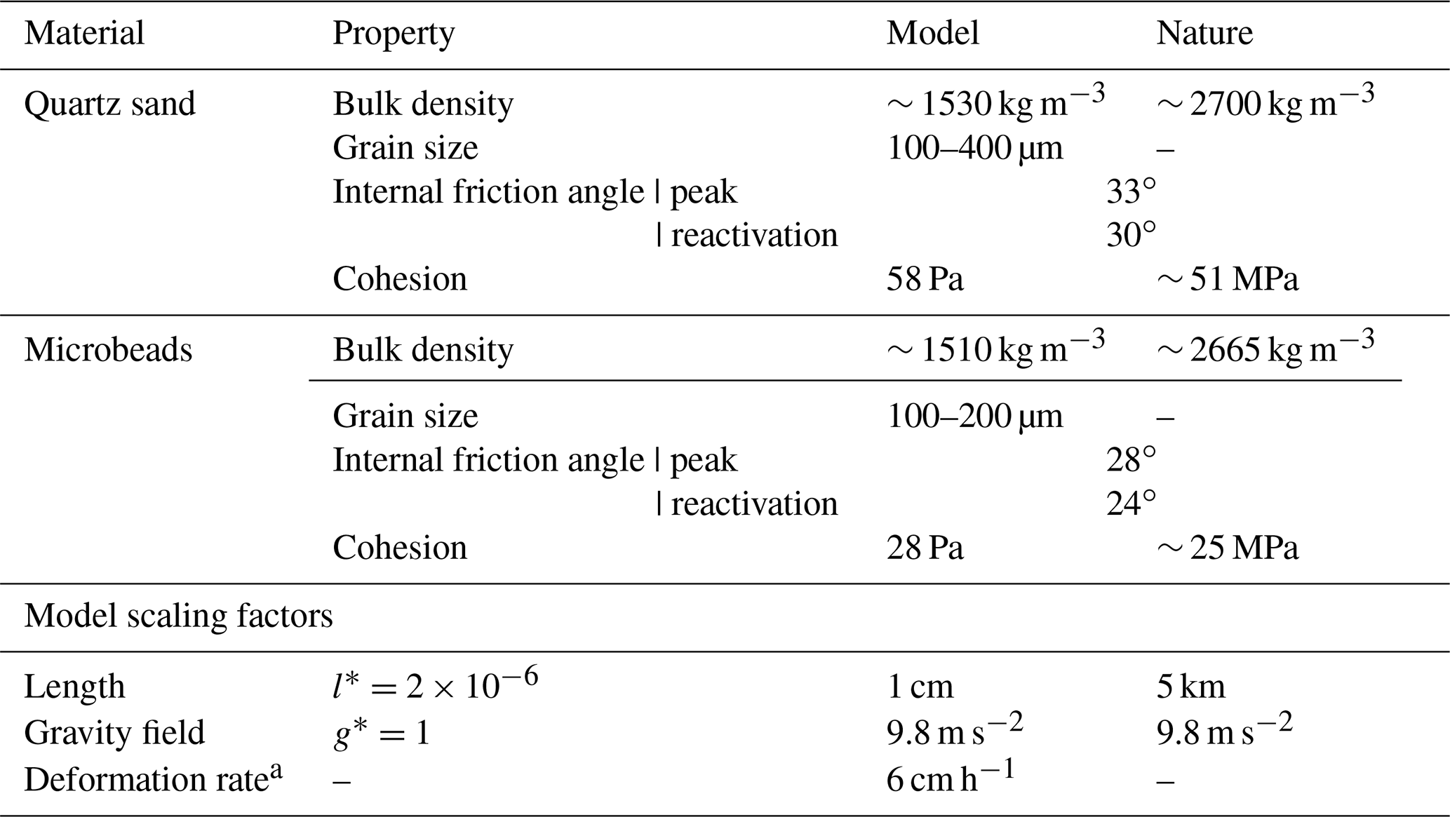
a Rheology of granular materials is strain-rate-independent; scaling would be applicable only to viscous materials.
2.3 Experimental limitations
Analogue modelling has inherent limitations, mainly related to the difficulty of reproducing complex rheologies and simulating realistic temperature evolution of rocks, therefore representing a simplification of nature (Koyi, 1997). In addition to this simplification, we have identified a number of limitations in our models. Sidewall friction in a push-type apparatus like ours is inevitable, and we therefore treat the internal side of the glass walls with a water-repellent product (Rain X®) as it reduces the sand–glass interface friction (Cubas et al., 2013). Since the side contact area is relatively small due to the thin layering, the unwanted side effect can be considered negligible for this series of experiments. This is supported by a consideration of the ratio between the top surface area and the side surface area in our experiments, which is 0.075 and thus below the value of 0.1, which Souloumiac et al. (2012) determined as the upper limit for negligible sidewall effects. The apparatus was designed to prevent material from sliding through the gap between the moving wall and the basal board during shortening. However, a very thin layer of microbeads still passes beneath the wall at early stages of deformation. As soon as crustal rupture is achieved, the entire thrust sheet is translated by the moving wall, and no extra material slides through the gap. Although we recognise that the deformation imposed in our experiments strictly creates shear zones, we refer for ease of comparison to natural examples to areas of material failure in this study as faults and/or thrusts.
3.1 Mechanics of basin inversion
In terms of orientation of principal stresses in the upper crust, basin inversion can be generally described as a change from an extensional setting, where σ1 is vertical, and σ3 is horizontal, to a compressional setting with σ1 horizontal and σ3 vertical. Assuming a Mohr–Coulomb criterion of failure for upper-crustal rocks, the dip angle at which normal and reverse faults should form can be calculated when the cohesion and angle-of-internal-friction values are known. Considering a rock analogue to the quartz sand employed in our experiments with an angle of internal friction of 33∘, extension would result in the formation of normal faults at ∼ 66∘ from the horizontal, while compression would lead to new thrusts forming at 33∘ (Fig. 3a). The resulting unfavourable orientation of normal faults to reactivate under compressive stress has been the subject of numerous studies (i.e. Jaeger and Cook, 1976; Cooper and Williams, 1989; Bonini et al., 2012; Zwaan et al., 2022), and it is the main reason why complete fault reactivation remains a challenging process to recreate by means of analogue modelling that employ materials with a simplified rheology in relation to nature. Analogous set-ups in numerical models have successfully simulated the reactivation of misoriented extensional faults by compressive stresses (e.g. Granado and Ruh, 2019). Despite the limitations of analogue materials, certain conditions such as obliquity of fault strike to σ1 (Del Ventisette et al., 2006), weaker basin infill (Panien et al., 2005), horizontal stress direction rotation (Ritter et al., 2016; Bonini et al., 2012), and type of post-rift sediments (Granado et al., 2017) have been tested in laboratory experiments and demonstrated to promote basin inversion and/or partial fault reactivation.
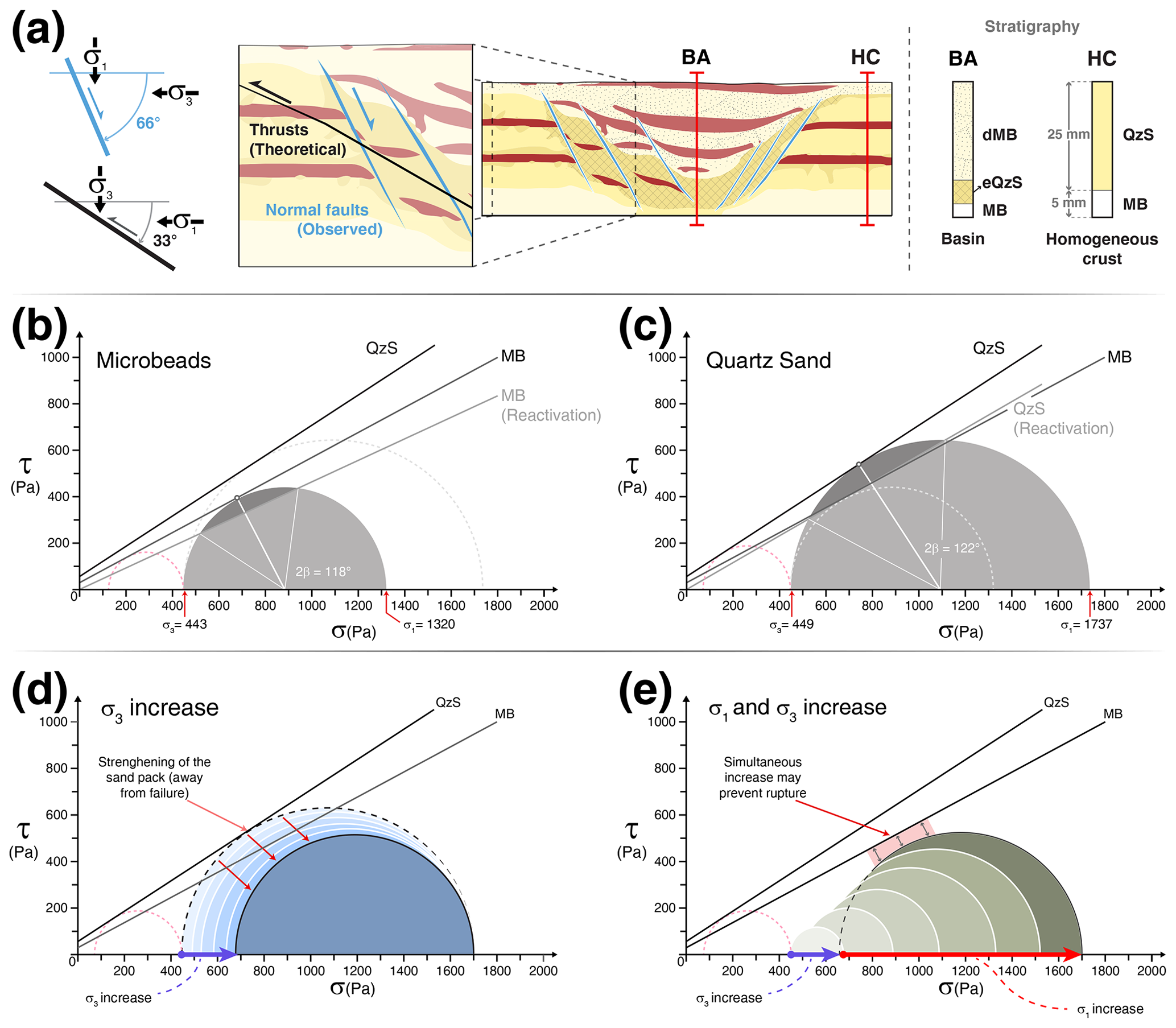
Figure 3Mohr plots representing stress state at the base of a 3 cm thick layer of (a) microbeads and (b) quartz sand (dotted red lines indicate the stress state in the extensional phase; β= angle of the failure plane). (c) Inset showing the state of the crust after extension and before the onset of compression, including observed (light blue, extensional) and theoretical (black, contractional) faulting and their spatial relationship with principal stresses σ1 and σ3. The right panel shows a schematic representation of stratigraphic columns for extensional basins (BA) and homogeneous crust (HC). Thicknesses of the syn-rift sediments, extended crust, and basal microbead layer are not included as they vary slightly between basins and experiments. (d) Schematic representation of Mohr circle theoretical evolution with a σ3 increase. (e) Schematic representation of Mohr circle theoretical evolution with simultaneous σ1 and σ3 increase. MB: microbeads; dMB: dyed microbeads; QzS: quartz sand; eQzS: extended quartz sand.
In this study we present various models with a different arrangement of internal mechanical heterogeneities prior to the onset of shortening: a reference model with a homogeneous crust and models with one, two, and three extensional basins (Fig. 2e). Considering the materials' density, cohesion, and angle of internal friction, Mohr diagrams representing the state of stress at the base of different sections of the models at the onset of shortening are plotted in Fig. 3b and c. With this theoretical framework (Fig. 3) as a basis, the following preliminary hypotheses can be drawn:
-
Under conditions where layers have the same thickness and similar densities, the lower angle of internal friction of the microbeads will make the model sedimentary infill more prone to failure with the onset of shortening. Thrusts are expected to propagate through the weaker extensional basins (Fig. 3b–c).
-
Normal faults in the models have a theoretical dip angle of 66∘. Even considering the lower reactivation values of internal friction, their reactivation during the shortening stage will be inhibited by their misorientation. Only a considerable rotation of σ1 about a vertical axis during shortening could favour fault reactivation, although observations from analogue models suggest that stress rotations would only be in the range of 5–15∘ (Bonini et al., 2012, and references therein) and would therefore be insufficient.
-
Vertical loading resulting from thickening in the sand wedge leads to strengthening of the sand pack as σ3 increases (Fig. 3d). With ongoing shortening, the thicker sand pile will require an increase of σ1 to maintain the same differential stress (Fig. 3e). This process may favour the reactivation of normal faults due to protracted compression within the basin or may lead to the formation of new thrusts to the foreland side of the extensional basin, the latter event being subject to the status of wedge stability (Sect. 3.2).
3.2 Critical taper theory
During shortening, the extensional basins are incorporated in a thrust wedge, which has heterogeneous material properties caused by the mixing of the microbeads of the basin fill with quartz sand. Critical taper theory (Dahlen, 1984, 1990) predicts a lower taper angle of 6.2∘ (unsoftened) to 7.2∘ (softened) for a pure quartz sand wedge overlying a thin microbead basal layer. Theoretical dip values of forward-verging thrusts are ∼ 20∘, and steeper back thrusts dip at ∼ 37∘ (Dahlen, 1990). The critical taper angle (which equals surface slope for our horizontal base experiments) for a pure microbead wedge is 7.9∘ (unsoftened) to 9.7∘ (softened). For our wedges, surface slopes between 6.2 and 9.7∘ can thus be argued to be valid values, where we would expect a tendency towards the higher values within the lower taper angle due to the mixing of microbeads into the sand (Buiter, 2012).
As thrust sheets are emplaced over the extensional basins during shortening the resulting strength increase caused by the increase in σ3 may be significant enough to keep the system stresses in a state such that the localisation of new thrusts would be determined by not only the internal rheological heterogeneities but also the need of the wedge to reach a critical taper value. New frontal thrusts then develop to decrease the taper angle.
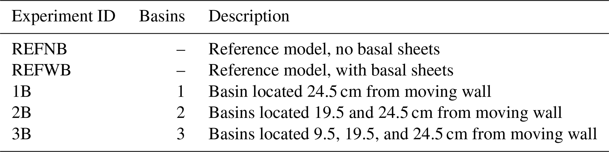
We carried out eight experiments with identical handling procedures (Table 2), and here we present the results of the five experiments with different initial conditions; three selected experiments were run twice to check for reproducibility. Two experiments, REFNB (no basal sheet) and REFWB (with basal sheet), examine shortening of a homogeneous layering, without extension, with the objective of having two reference shortening experiments to compare our basin inversion experiments against. The basin inversion experiments (1B, 2B, and 3B, or EXP1B, EXP2B, and EXP3B) include an extensional phase forming one, two, or three extensional basins, respectively. For description purposes, a terminology based on the analogy with the location of the foreland and hinterland in fold-and-thrust belts is used, and the extensional basins are called proximal, central, and distal based on their proximity to the moving wall (Fig. 2e).
4.1 Reference experiments
Experiment REFNB (reference experiment, no basal sheets) consists of a 5 mm thick microbead layer overlain by a 25 mm thick cover of quartz sand, with interbedded coloured horizontal layers that act as passive markers. No basal plastic sheets are employed in this model. Results of experiment REFNB show a typical piggyback deformation style, with thrust sheets developing in sequence and being gradually transported towards the foreland. Shortening is accommodated first by a pop-up structure consisting of a forward and back thrust stemming from the basal detachment layer 2.3 cm from the moving wall (T1 in Fig. 4a). Activity in the back thrust decreases, and strain is then only accommodated for by the frontal thrust T1 until a new pop-up structure forms, 12.9 cm from the moving wall (T2 in Fig. 4a). The entire thrust sheet is translated towards the foreland until a third pop-up structure develops, after 16 cm of displacement (T3 in Fig. 4a). After 20 cm of displacement, the measured wedge taper angle is 8.5∘ (Fig. 4a).
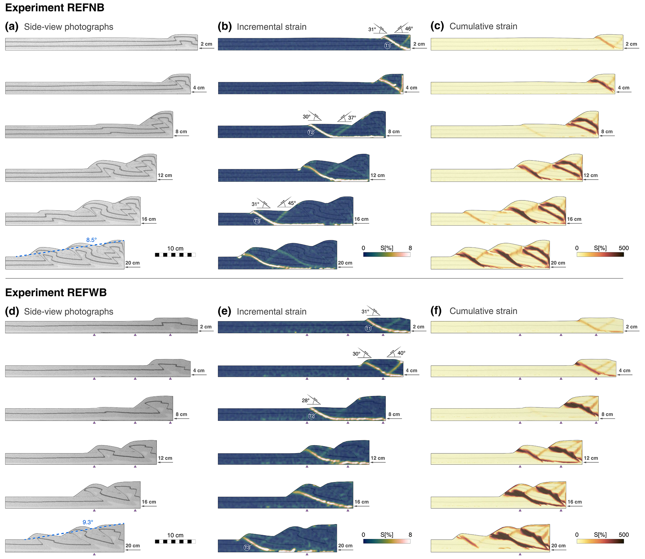
Figure 4Deformation evolution, comparison between reference experiments. Experiment REFNB, no basal sheet: (a) side-view photographs, (b) incremental strain, and (c) cumulative strain. Experiment REFWB, with basal sheet: (d) side-view photographs, (e) incremental strain, and (f) cumulative strain.
Experiment REFWB (reference experiment, with basal sheets) was designed to create the exact same initial conditions as experiment REFNB, with the only addition of including plastic basal sheets fixed to the apparatus base, with vertical sub-millimetric steps – perpendicular to the shortening direction – located 9.5, 19.5, and 24.5 cm from the initial position of the moving wall (Fig. 4b). The plastic sheets are used in subsequent experiments to create extensional basins and remain in a passive role during the shortening phase. We test here their potential influence during shortening. Experiment REFWB develops a pop-up structure almost immediately after the initiation of the wall movement (T1 in Fig. 4b), as observed in experiment REFNB. However, in REFWB the pop-up structure forms 7 cm from the moving wall, which is closer to the edge of the first basal sheet step, meaning that its associated basal velocity discontinuity could play a role in determining the location of the first thrust sheet in the accretionary wedge evolution. After approximately 7.5 cm of displacement, the initial pop-up structure is progressively abandoned, and a new frontal thrust forms towards the foreland, stemming from the basal detachment layer 14 cm from the moving wall (T2 in Fig. 4b). In this case, the location of the frontal thrust and its conjugate back thrust is not aligned with one of the basal sheet steps (Fig. 4b). Most of the shortening is accommodated by the second frontal thrust until the system reaches ∼ 17 cm of displacement. At this point, a new pop-up structure develops, stemming from the basal detachment layer 20.5 cm from the moving wall (T3 in Fig. 4b). The new frontal thrust localises most of the wedge deformation until the final stages of the experiment (Fig. 4b). After 20 cm of displacement, the measured wedge taper angle is 9.3∘ (Fig. 4b)
The overall evolution of the accretionary wedge in REFWB is similar to experiment REFNB. Both experiments were run twice, showing little variability in terms of pop-up structure formation and thrust localisation. The velocity discontinuities formed by the sub-millimetric geometrical steps of the basal sheets only influence the model in early stages, defining the onset of the first thrusts. However, the fact that the sheet edges are not aligned with the subsequent floor thrusts allows us to assume that their effect in the evolution of the modelled accretionary wedge is negligible for the purpose of our study.
4.2 Experiment 1B: one extensional basin
Experiment 1B consists of two stages. An initial stage of 3 cm extension in which an extensional basin with border faults located between 24.5 and 27.5 cm from the wall (measured along the base) is created, followed by a stage of 20 cm of compressional displacement. Shortly after the initiation of shortening, frontal and back thrusts develop approximately 5 cm from the moving wall (T1 in Fig. 5). During the first 6 mm of displacement, before the onset of the first frontal thrust, the distal extensional basin shows internal horizontal compression, reaching peak values of up to 16 % of cumulative strain (7 % on average) but without fault reactivation or the formation of new thrusts. No further internal deformation of the basin is observed between 0.6 and 4 cm shortening.
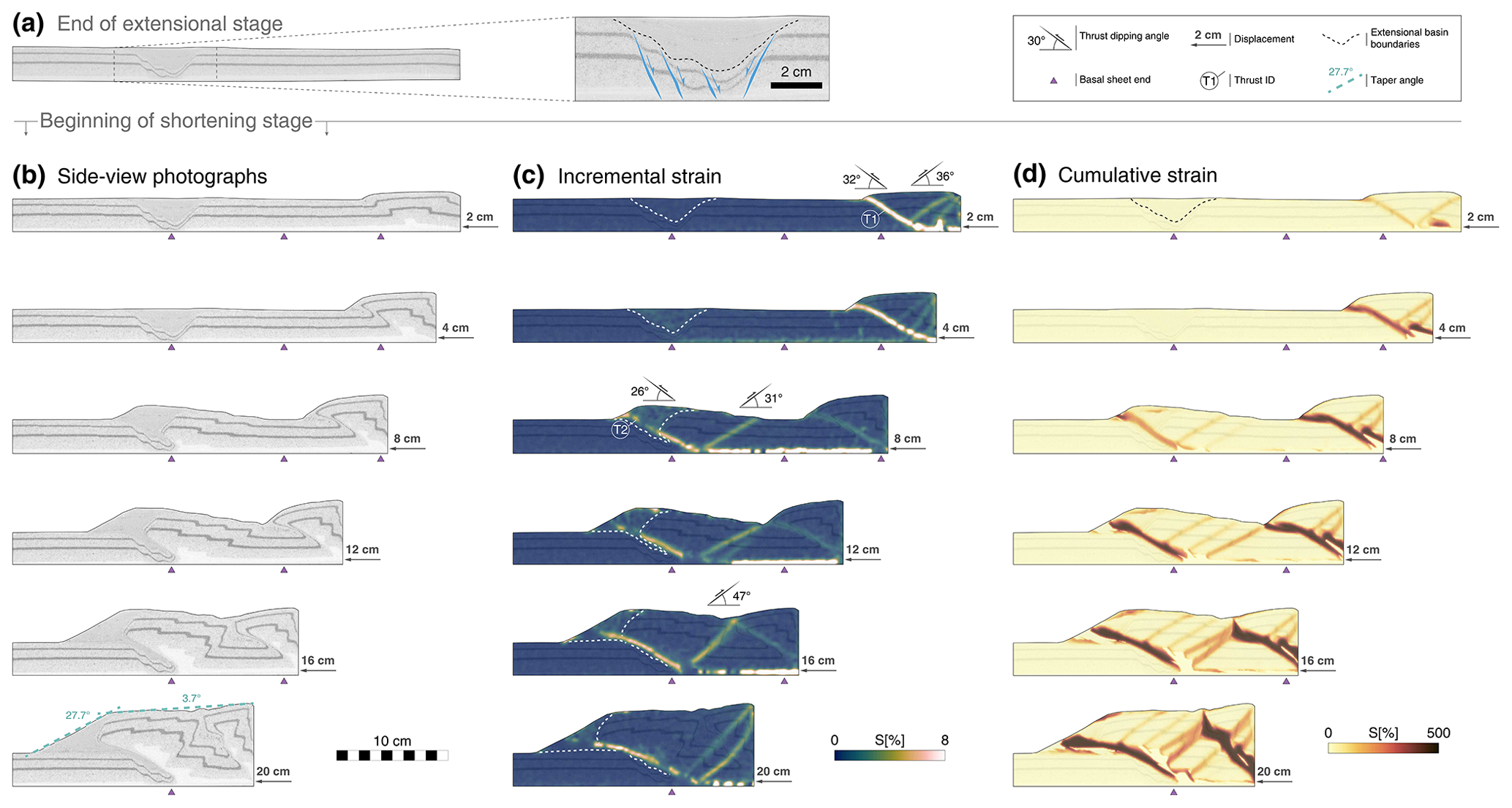
Figure 5Experiment 1B summary. (a) Side-view photograph and interpreted close-up view at the end of the extensional stage. Shortening stage evolution, showing (b) side-view photographs, (c) incremental strain, and (d) cumulative strain.
The initial thrust sheet is transported towards the foreland, and after 5 cm of total displacement, strain accommodation is partitioned, and stress builds up again in the extensional basin. Subsequently, the initial forward thrust is progressively abandoned, and strain localisation is transferred entirely near the pre-existing extensional basin (T2 in Fig. 5). A new forward thrust forms along the limit between the faulted blocks in the foreland side and the weak microbead depocentre filling, without reactivating the extensional border faults. The extensional faults on the hinterland side are cross-cut, and the thrust sheet propagates towards the foreland, above the pre-rift sediments (Fig. 5; 8 cm displacement). With ongoing deformation, no further deformation is observed beyond the extensional basin, and the wedge grows in height through the development of three new back thrusts that form progressively towards the location of the wall. After 20 cm of displacement, a wedge taper angle cannot be accurately estimated, as the wedge is in transition to a critical taper, and two distinctive wedge fronts can be established at 27.7∘ (determined by the angle of repose of the microbeads) and 3.7∘ in the more planar, higher section (Fig. 5).
4.3 Experiment 2B: two extensional basins
The 3 cm extensional phase for experiment 2B leads to the formation of a distal basin with border faults located between 24.5 and 27.5 cm from the wall (measured along the base) and a central basin with border faults located between 19.5 and 22.5 cm from the wall. Initial compressional deformation is accommodated by the development of a pop-up structure, forming 14.3 cm from the wall, aligned with the pre-existing extensional basin located closer to the hinterland (T1 in Fig. 6). The frontal thrust cross-cuts the border faults on the hinterland side and progressively transports the basin fill over the pre-rift sand pack, towards the foreland. After 2.3 cm of displacement, a new forward thrust develops in the proximity of the wall (T2 in Fig. 6). As observed in experiment 1B, the early development of a thrust sheet located relatively farther away from the wall than in the reference models causes the wedge to grow in a subcritical, unstable manner (Fig. 6; 4 cm displacement). Internal deformation of the wedge is therefore controlled by a new forward thrust forming 2.4 cm from the moving wall (T2). This out-of-sequence thrust accommodates shortening for another 2.5 cm of displacement, when the frontal thrust T1, located along the weak graben fill, is reactivated (Fig. 6; 8 cm displacement). PIV analysis at 8 cm of displacement indicates no normal fault reactivation, but the frontal thrust does show a strong deflection of its dip angle, from 20∘ at the base to 37∘ when it interacts with the extensional basin (Fig. 6; 8 cm displacement). Coevally, a series of back thrusts become active on the hinterland side of the thrust sheet as the wedge continues to advance. At later stages, the frontal thrust located along the central basin and its conjugate back thrust decrease their activity, and strain localisation is progressively transferred to the distal basin (Fig. 6; 12 cm displacement). Before the onset of a new pop-up structure in the distal basin, cumulative strain within the syn-rift strata reached values of up to 24 %. After 12 cm of total displacement, shortening in the foreland is accommodated first by a back thrust aligned with the extensional basin border faults, later replaced by the formation of a new forward thrust (T3 in Fig. 6). At 16 cm of displacement, the wedge continues to grow, with most of the strain localised along the two forward thrusts and steeply dipping back thrusts (Fig. 6; 16 cm displacement). The final stages of deformation are characterised by a new pop-up structure forming in the foreland (T4 in Fig. 6). The wedge taper angle after 20 cm of shortening is 9.7∘ (Fig. 6).
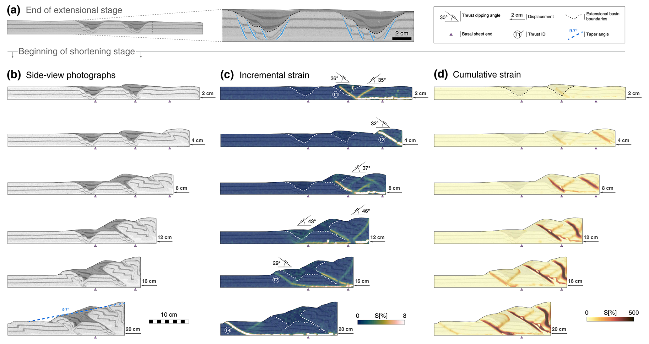
Figure 6Experiment 2B summary. (a) Side-view photograph and interpreted close-up view at the end of the extensional stage. Shortening stage evolution, showing (b) side-view photographs, (c) incremental strain, and (d) cumulative strain.
4.4 Experiment 3B: three extensional basins
Experiment 3B is carried out following the same procedure as experiments 1B and 2B, but now creating three extensional basins before the onset of shortening. The extensional phase for this experiment results in the first basin located between 28.5 and 31.5 cm from the moving wall, the second basin between 19.5 and 22.5 cm from the moving wall, and the third and last basin located between 9.5 and 12.5 cm from the moving wall (all measured along the base). Early compressional stages are characterised by the formation of a forward thrust, with its location being controlled by the weak basin fill of the basin, cross-cutting the extensional border faults located on the side of the moving wall (T1 in Fig. 7). This forward thrust is followed by the formation of a back thrust, both stemming from the basal detachment layer 5.8 cm from the moving wall. Close inspection of PIV data shows that the interior of the proximal extensional basin localises up to 20 % of strain before the onset of the pop-up structure. After 6.5 cm of displacement, strain is partitioned and progressively transferred to the central extensional basin, where a new forward thrust develops, aligned with the interface between the rifted blocks and the weak sedimentary infill, as occurred in earlier stages of this experiment (T2 in Fig. 7). No clear reactivation of border faults can be detected in this process, although the high angle (49∘) of the associated back thrust could be associated with the partial reactivation of the hinterland border faults. The central basin shows horizontal compression and a partial uplift of 2.2 mm prior to crustal failure. Cumulative strain is calculated to reach values of up to 26 % within the basin before the onset of new thrusts.

Figure 7Experiment 3B summary. (a) Side-view photograph and interpreted close-up view at the end of the extensional stage. Shortening stage evolution, showing (b) side-view photographs, (c) incremental strain, and (d) cumulative strain.
Strain localisation along this central basin is short-lived, and a new forward thrust develops 16.2 cm from the moving wall, with its localisation being determined by the existence of the distal basin (T3 in Fig. 7). The new frontal thrust becomes the most active structure at this stage of the accretionary wedge evolution. Two new back thrusts form and show a noticeable deflection in their dipping angle when interacting with the uplifted central basin. After 16 cm of displacement, the entire sedimentary fill of the first basin is transported past the frontal thrust tip point. At this stage, internal deformation of the wedge is accommodated by the frontal thrust T3 and its conjugate back thrust, as well as by a forward thrust stemming from the base of the wall and aligned with the location of the weak remobilised sediments in the interior of the wedge (Fig. 7; 16 cm displacement). After 20 cm of shortening, strain is localised only along the frontal thrust and a back thrust that transects the entire wedge, with a variable dip angle of 39∘ in its lower section and 60∘ in its upper section (Fig. 7; 20 cm displacement). The measured wedge taper angle is averaged to 10.7∘, although two wedge fronts with different slopes can alternatively be measured as 28 and 5.5∘ (Fig. 7).
5.1 Overall evolution of the experiments
Certain features can be observed across all experiments with pre-existing extensional basins. Independent of the position of the graben (proximal, central, or distal), detailed analysis shows that normal fault reactivation sensu stricto is not the main mechanism for basin inversion during shortening stages. The change from extension to shortening is instead characterised by a partial inversion that can be outlined in three stages:
-
Horizontal stresses are transferred across the quartz sand (analogous to stronger crust), resulting in the shortening of the microbeads (analogous to weak sedimentary infill) and an associated upward bulging. Cumulative strain localising in the interior of the basins prior to the development of forward thrusts ranges from 5 %–26 %. When multiple extensional basins are present, the proximal basin absorbs most of the stress transferred through the quartz sand as it is closest to the wedge.
-
Thrusts develop in the microbeads and produce the partial inversion of the basin, resulting in the asymmetric dome-shaped deformation of the microbeads (syn-rift growth strata). In all cases, the thrust producing the internal deformation of the basin is a frontal thrust, except for the distal basin in EXP2B, where the basin uplift is accommodated by both a frontal thrust and a back thrust aligned with the basin border faults instead (Fig. 6; 12 cm displacement).
-
The mechanism of shortening accommodation finally ends with the development of a new frontal thrust, located farther away from the moving wall. This mechanism is the result of two processes combined: (1) the prograding wedge pushes new material on top of the extensional basin to the point that the locally increased crustal thickness makes it rheologically stronger (through the increase in vertical stress), thereby making the region towards the foreland relatively weaker, and (2) the orogenic wedge is transitioning towards its critical taper angle and needs to grow forward to decrease its angle and remain in the stable field, following critical taper theory.
Beyond these similarities in the general mechanism of (partial) basin inversion, there are important differences in the spatio-temporal evolution of deformation and thrust sequencing as a function of the number of extensional basins.
EXP1B shows the largest thrust spacing among the experiments, with the first pop-up structure developing in the vicinity of the moving wall (Fig. 5; 2 cm displacement), followed by the transfer of horizontal stresses onto the pre-existing extensional basin, located ∼ 17 cm beyond the basal detachment of the initial frontal thrust (Fig. 5; 8 cm displacement). This experiment shows the maximum amount of strain accumulation in the extensional basin prior to its failure by shortening and represents the distal extensional basin with the earliest evidence of a certain degree of inversion. The emplacement of frontal thrusts differs from the reference experiments as in EXP1B they are conditioned by the location of the extensional basin (cf. Figs. 4 and 5). The distal extensional basin acts as an efficient localiser that takes up stress, and no thrusts develop beyond its position throughout the entire experiment.
EXP2B is the only experiment of this series that developed out-of-sequence frontal thrusts. The first frontal thrust localised along the central extensional basin, before strain was accommodated by a pop-up structure in the vicinity of the wall (Fig. 6; 4 cm displacement). Thrust spacing closely resembles that of the reference experiments, although they follow a different chronological order. Contrary to what is observed in the other experiments, the distal graben normal faults that are cross-cut are those located at the foreland side of the basin, resulting in an oppositely verging uplift of the sedimentary infill (Fig. 6; 16 cm displacement)
EXP3B evolution is characterised by in-sequence thrusts that localise along each of the extensional basins (Fig. 7). The main difference with EXP1B and EXP2B is that the inversion of the central basin is more complex: early stages of deformation produce partial uplift, but it is short-lived as prograding sediments from the wedge result in an overburden that makes the basin rheologically stronger, and deformation is soon transferred to the distal basin (Fig. 7; 12 cm displacement). As in EXP1B, no further shortening structures are observed beyond the position of the distal basin (Fig. 7; 20 cm displacement).
5.2 Comparison to critical taper theory
Fault dip angles in the analogue experiments average 26–32∘ for the forward thrusts and 31–46∘ for the back thrusts. The forward thrusts are thus somewhat shallower than the theoretical dip angle of 33∘ for reverse faults in undeformed sand, whereas the back thrusts are mainly steeper than this value. For mature wedges, the theoretical dip angles become 20∘ for forward thrusts and ∼ 37∘ for back thrusts (Dahlen, 1990; Sect. 3.2 herein). The measured forward thrusts are thus steeper than the theoretical value, whereas the back thrusts could be argued to fit fairly well. However, in our opinion the thrust dip measurements have limited validity as they are a manifestation of internal wedge deformation during its transition to become critical.
When comparing the experiments in which basins are incorporated in the thrust wedge to the reference experiments without basins, we find a perceptible effect of the pre-existing extensional basins on the final taper angle of the wedge: the taper angle increases. The reference experiments with a homogeneous quartz sand layer had measured taper angles of 8.5 and 9.3∘ after 20 cm of shortening, which are somewhat higher than the predicted values of 6.2–7.2∘. Measured values for experiments 2B and 3B are higher again, at 9.7 and 10.7∘, respectively (Fig. 8). In experiments 1B and 3B the shape of the advancing wedge is irregular, making it harder to draw a best-fit line that determines the taper angle (Fig. 8c and d). In these cases, the protracted localisation of shortening along the distal extensional basin results in greater accumulation of scraped-off and slope materials in the frontal section. As a result, the frontal slope is determined by the angle of repose of the mix of quartz sand and microbeads. When comparing experiments 1B, 2B, and 3B after the same amount of shortening (Fig. 8), experiment 2B displays the lowest wedge taper angle, as it formed a new frontal thrust at a slightly earlier stage of deformation (Fig. 8c–d). However, the overall temporal evolution of the wedge taper angle during shortening is similar for the experiments with a previously extended crust. Results point towards an increase in the taper angle in comparison to wedges with a homogenous crust (cf. Fig. 8a–b and c–d). This agrees with our predictions (Sect. 3.2) as the inclusion of the weaker microbeads of the basin fill is expected to increase the taper angle.
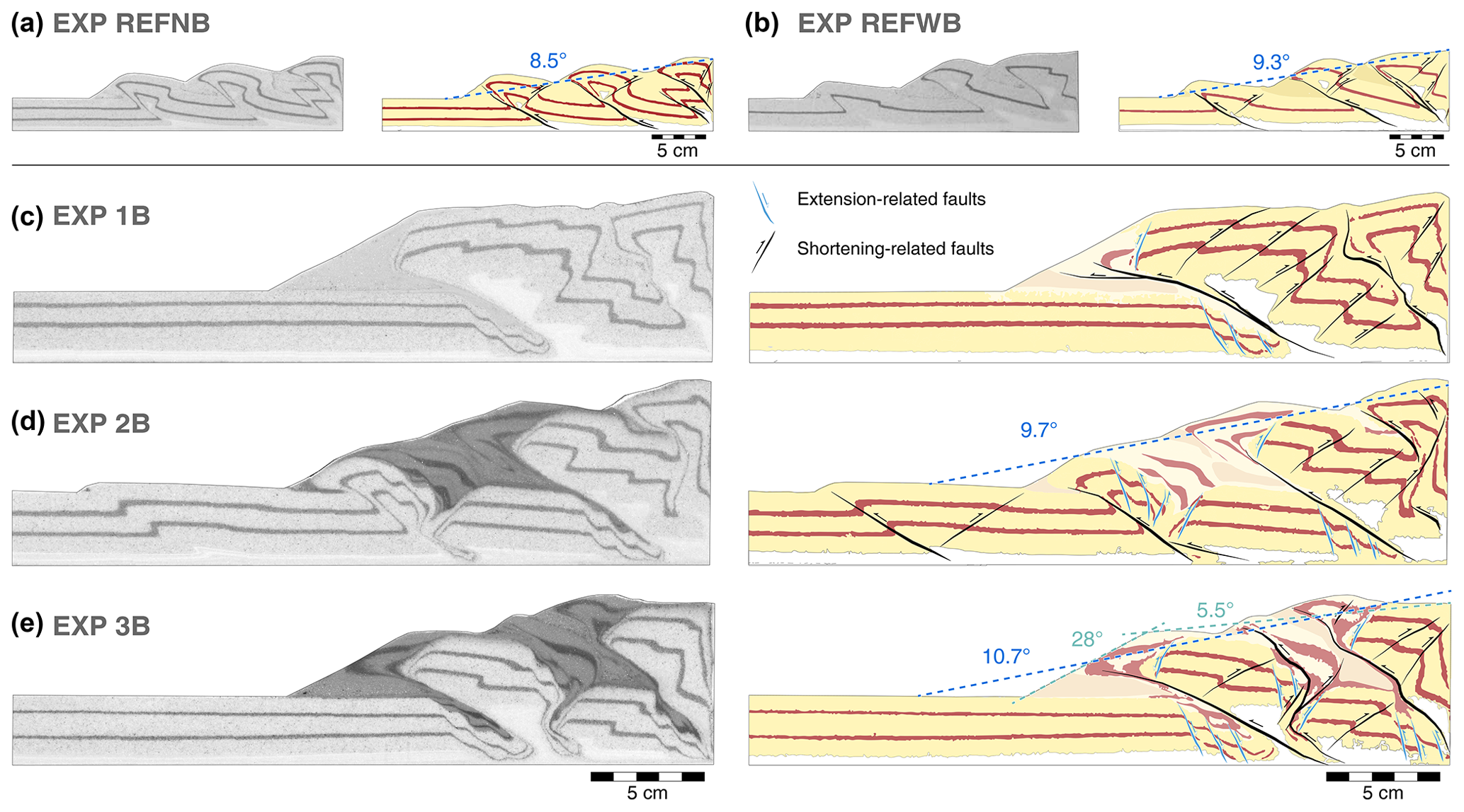
Figure 8Side-view photographs and interpretation sketches for all models after 20 cm of displacement, including visual guide for taper angle measurements. Values for EXP1B could not be determined as the taper is in transition into a critical taper, where no clear valleys or peaks are yet discernible in order to display a best-fitting line (Stockmal et al., 2007).
5.3 Mechanisms of basin inversion in the experiments
In terms of local structures and transient mechanisms of strain accommodation, we can classify partial inversion in the models into three stages: basin shortening and uplift, thrust localisation and reactivation, and deformation relocalisation due to changes in brittle strength.
5.3.1 Basin shortening and uplift
Early stages are generally manifested by the displacement of the crustal section between the moving wall and the most proximal extensional basin, as a whole, and in the shortening direction (Fig. 9). This crustal section is rheologically stronger than the extensional basin infill; therefore stress is transferred along the crust, and shortening is absorbed by the unconsolidated sediments of the basin. This produces an early compaction and subsequent upward bulging of the basin fill, prior to the failure of the crust in the form of a thrust (Fig. 9).
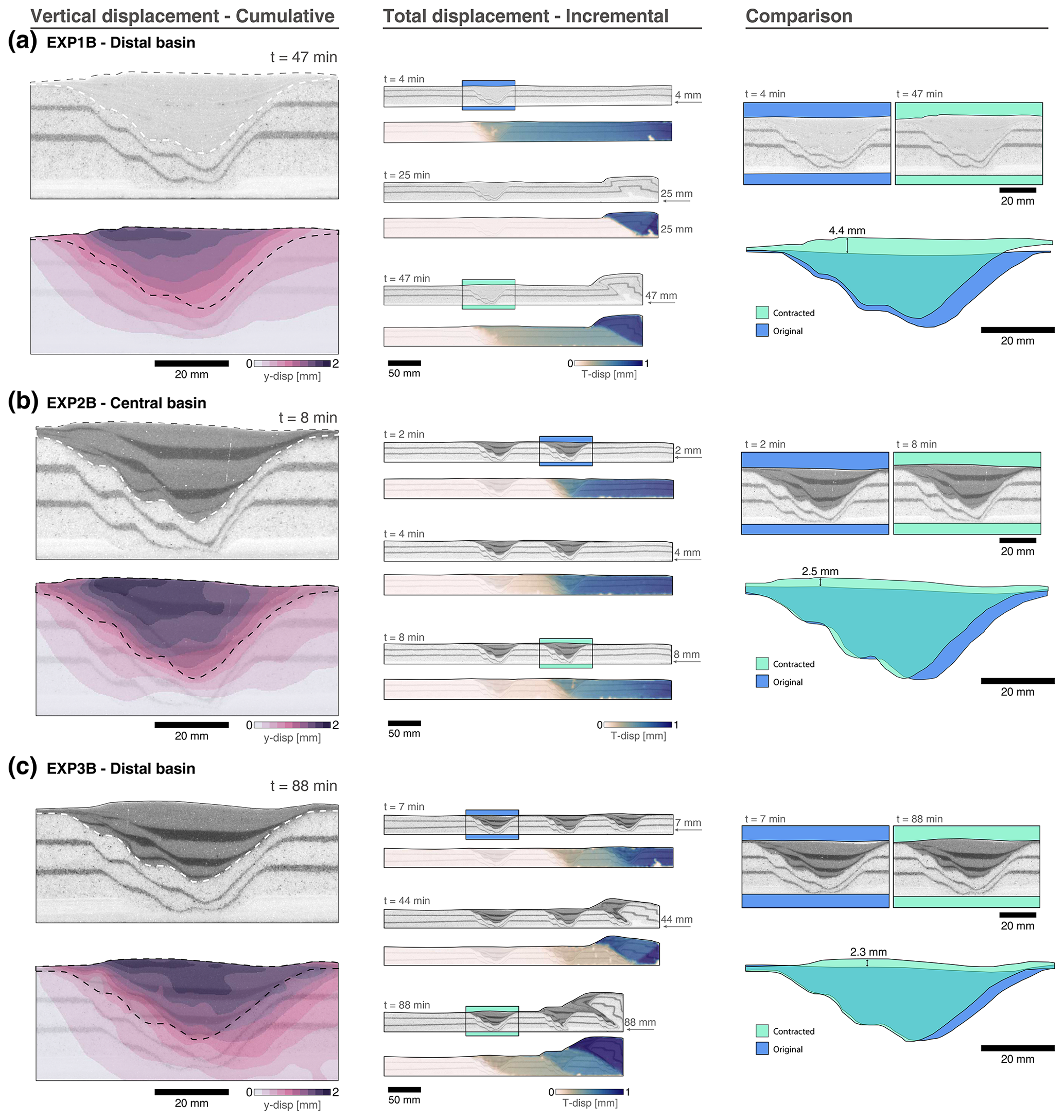
Figure 9Close-up view of selected basins. In EXP2B, despite having only two basins, the basin closest to the moving wall is referred to as “central” for ease of comparison between experiments. The left panel shows Y displacement (vertical) before crustal failure, the central panel shows total displacement at the indicated time intervals, and the right panel is a drawn comparison between the original basin and its status before thrust development.
During this initial stage, there is no displacement observed distalward from the basin for relatively long periods of time, meaning that extensional basins act as an efficient feature to localise stress and prevent further transfer within the crust (Fig. 9, central panels). However, in the case of EXP1B, where the distance between the moving wall and the extensional basin is relatively higher (28.5 cm vs. 19.5 and 9.5), shortening is initially manifested as a classic pop-up structure near the moving wall, preceding the basin fill compaction stage. This observation indicates that, in conditions analogous to our models, there may be a distance threshold of how much compressional stresses can be transferred from the orogenic front laterally far into the crust.
An uplift of up to ∼ 9 % of its initial thickness and a horizontal contraction of up to ∼ 8 % of its initial width is observed among the extensional basins in all models (Fig. 9). PIV analysis shows that up to ∼ 25 % of strain can be accumulated in the interior of the extensional basins before any type of faulting is manifested. These observations are in line with previous analogue modelling results (Panien et al., 2006) and field studies (Butler, 1989; Chadwick, 1993; Gillcrist et al., 1987; Granado et al., 2018), where it has been identified that inversion of extensional basins initiates by bulk shortening of the graben fill, localised minor reverse faulting, buttressing with associated folding, and subsequent regional upwarp (Fig. 9).
5.3.2 Thrust localisation and reactivation
After the initial stage of stress build-up in the interior of the basins, crustal failure – identified as such when incremental strain values are over 1 % – is manifested as forward-verging thrusts. Except for the early pop-up structure formed in the vicinity of the moving wall in EXP1B (Fig. 5; 2 cm displacement), all initial frontal thrusts are localised along the pre-existing extensional basins. These results are in line with early observations of how extant hinterland-dipping normal faults favour the development of foreland-directed thrusts (Cooper and Williams, 1989). Thrusts that cross-cut the basin have dip angles in the range of 20–38∘. When analysed in detail, examples of EXP3B and EXP2B show that dip angle variations within the thrust are associated with the location of the pre-existing normal faults (Fig. 10b and d), without reactivation sensu stricto due to their misorientation. The only significant difference in this process is observed in the distal basin of EXP2B, where the weak sedimentary infill determines the position of the back thrust instead of the frontal thrust. A forward-verging thrust forms that cuts through the homogenous crust (Fig. 10d).
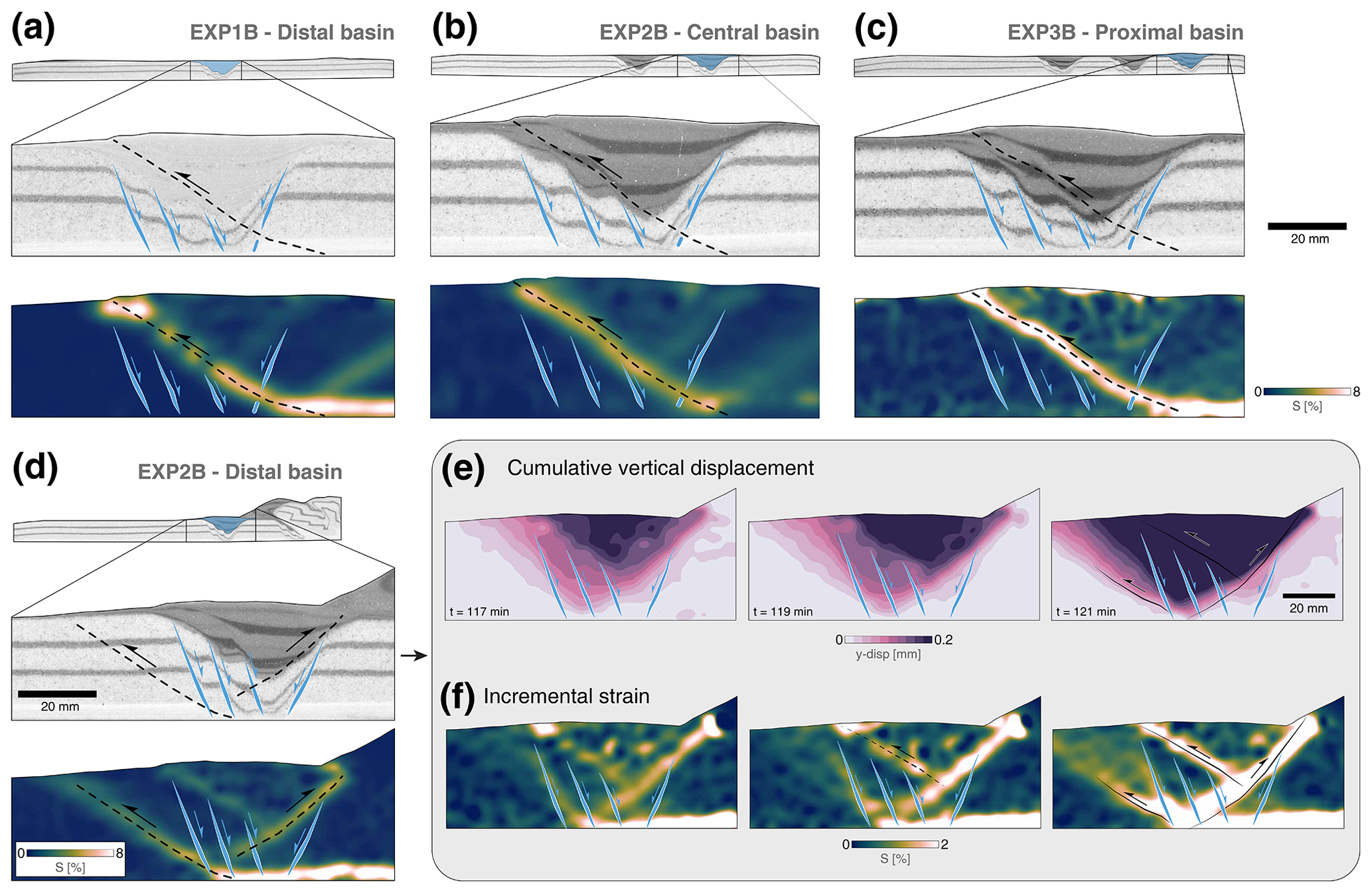
Figure 10Close-up view of selected basins, highlighting thrust localisation. (a) Experiment 1B, distal basin. (b) Experiment 2B, central basin. (c) Experiment 3B, proximal basin. (d) Experiment 2B, distal basin. (e) Close-up view visualising different time increments for cumulative vertical displacement and (f) incremental strain of the distal basin in EXP2B.
Considering that strain softening in fine sands is relatively minor, and therefore faults do not weaken considerably, it is mainly due to the misorientation of normal faults that their reactivation and inversion do not occur in any of the basins, with one potential exception in the distal basin of EXP2B (Fig. 10d–f). Prior to the formation of the pop-up structure that lifts the basin up, strain builds up along the middle and lower part of both border faults (Fig. 10f; 117 min). However, the degree of strain localisation is too low and short-lived for normal fault reactivation, and two frontal thrusts form instead (Fig. 10f; 121 min). When this happens, normal faults are cross-cut as in the rest of the extensional basins located at the foreland of the modelled orogenic wedges.
5.3.3 Variations in brittle strength
Our modelling outcomes allow the identification of the chronological order in which crustal thickening and vertical loading may result in locally stronger areas of the crust. The rheological heterogeneities formed by the basins play an important role in determining how long lived each of the frontal and back thrusts are. Prior to thrust sheet translation and the associated vertical load, the weakest area is always the interior of the basins (see Sect. 4), where shortening is expected to localise. Thrusts effectively form in the proximity of the basin and cross-cut border faults. With ongoing deformation and transport of material on top of the extensional basins, the previously weaker interior becomes stronger due to an increase in the vertical principal stress σ3 (Fig. 3e). At this point, strain localisation and overall evolution of deformation becomes a trade-off between (a) the location of the rheologically weaker sections of the crust and (b) the need of the wedge to reach the critical point predicted by critical taper theory.
In EXP2B, before reaching 12 cm of total displacement, an early frontal thrust that localised along the central extensional basin is active, while new frontal and back thrusts start developing in the vicinity of the distal extensional basin (Fig. 11a; 117 mm displacement). Initially, the new back thrust seems to accommodate most shortening in the new orogenic front. However, the early-formed thrust sheet continues to transport material on top of the basin until the vertical load is sufficiently high to hinder the partial basin inversion (Fig. 11a; 127 mm displacement). Strain subsequently jumps to the foreland and localises beyond the distal extensional basin, as a mechanism to aid the wedge taper angle to a critical value.
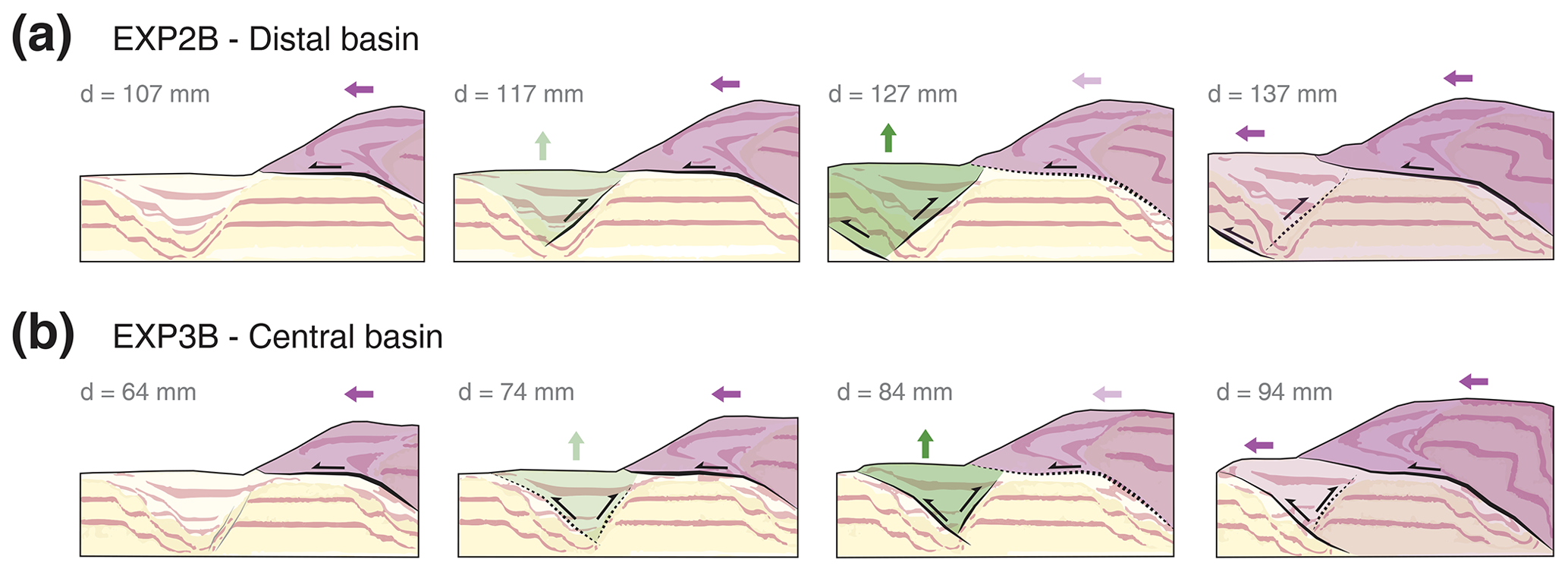
Figure 11Interpreted sections of selected experiments showing thrust sheet progression and impact on basin inversion. (a) Experiment 2B, distal basin. (b) Experiment 3B, central basin.
A similar process is observed in the central basin of EXP3B. The forward-verging thrust formed early along the proximal extensional basin is active at the moment of stress build-up and strain localisation in the central basin (Fig. 7; 74 mm displacement). Translation of the thrust sheet on top of the partially inverted central basin creates the same hindering effect as in EXP2B, and the back thrust becomes inactive. Instead of transferring all the stress to the new orogenic front, both forward thrusts are coevally active for ∼ 20 min (2 cm of displacement), until the growth of the wedge is such that shortening is accommodated by a new frontal thrust along the distal extensional basin (Fig. 11b; 94 mm displacement). After this process, internal deformation of the wedge ceases, and all shortening is accommodated by the new orogenic front. These two examples are indicative of how extensional basins in foreland fold-and-thrust belts are likely to localise the onset of thrusts, but their effectivity, duration, and chronological order will depend on their initial position, distance between basins, and relative distance to the indenter.
5.4 Comparison with previous case studies
Our modelling results can be compared to case studies of fold-and-thrust belts forming over previously extended crust. While aspects such as crustal composition, type of syn-rift infill, shortening direction and its variation over time, and distances or thicknesses may differ, we argue that our findings can be extrapolated from modelling to nature in order to provide first-order insights on the evolution of deformation and basin inversion in fold-and-thrust belts. Here we compare the most relevant aspects of our models with natural examples across multiple length scales.
5.4.1 Carpathians
The Carpathian Mountains in central eastern Europe formed as a result of the subduction of the European plate below the Adriatic plate and the associated closure of two extensional basins located behind an extended margin (e.g. Picha et al., 2006) (Fig. 12a, left panel). These conditions resemble those for EXP3B, where three sections of previously extended crust are subjected to shortening mainly from one direction (i.e. moving wall). Convergence and early stages of collision, lasting from the Late Cretaceous to the Palaeocene, initially manifested as a series of frontal thrusts that localised along the pre-orogenic extensional basin closest to the orogenic front (Picha et al., 2006; Fig. 12a, left panel). As interpreted for EXP3B, there is also evidence of contraction and partial inversion of the extensional basins at these early stages in the Carpathians, without manifestation of crustal rupture at the surface. While estimating the amount of shortening having occurred in the extensional basins in such natural scenarios can be difficult, from our models we can quantify up to 19 % and 27 % of cumulative strain in the central and distal basins, respectively, before new contractional faults form in their surroundings. Ongoing deformation in the Late Oligocene was characterised by the formation of in-sequence thrust sheets along the central basin (Magura Flysch; Fig. 12a, left panel), forming the Inner Carpathians. This stage culminated in the cross-cutting of the central basin as the indenter formed by the Adriatic plate continued its progression towards the European Plate. At later stages, strain localisation was transferred to the most distal extensional basin (Silesian unit; Fig. 12a, left panel), giving rise to the Outer Carpathians. A very similar behaviour was observed in EXP3B, where the central basin showed evidence of mild basin inversion until it was cross-cut by the incoming thrust sheet from the accretionary front (Fig. 12a, right panel). The final stages in EXP3B were characterised by the formation of a wedge with a frontal thrust that originated along the most distal extensional basin, which uplifted and folded the syn-extensional strata (Fig. 12a, right panel). Similarly, the Late Miocene in the Carpathians is distinguished by the progression of the fold-and-thrust belt, which completely uplifted the distant extensional Silesian units (Fig. 12a, left panel), which is the only syn-extensional unit widely exposed in the surface of the western Outer Carpathians (Picha et al., 2006). Both the natural prototype and the experimental results indicate that, when multiple extensional basins are present, the most proximal one will absorb the majority of the stress at initial stages, and the complete tectonic wedge will then continue its deformation, in sequence, from the deformation front towards the foreland.
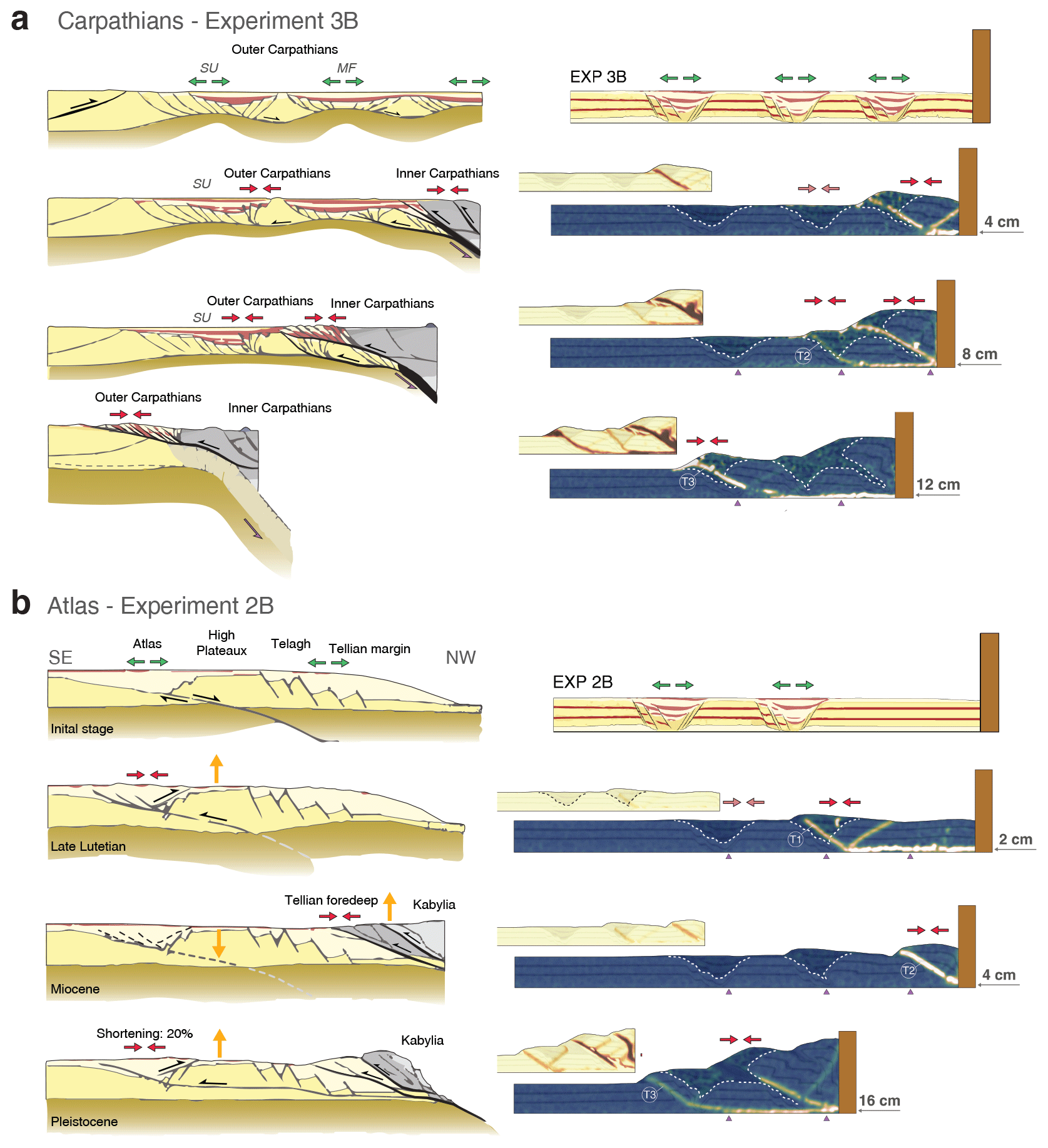
Figure 12Temporal evolution comparison between selected natural examples and our analogue modelling results. (a) Carpathians vs. EXP3B (redrawn from Picha et al., 2006). MF: Magura Flysch; SU: Silesian Unit. (b) Atlas vs. EXP2B (redrawn from Bracène and de Lamotte, 2002).
5.4.2 Atlas
The Atlas Mountains in north-western Africa formed as a result of multiple episodes of extension and compression, governed by major changes in global plate kinematics. Two main stages of deformation can be discerned for them: first an extensional phase, linked to the opening of the Maghrebian Tethys and North Atlantic oceans, and then the posterior compression and inversion, associated with the convergence and collision of the African and European plates (Mattauer et al., 1977; Roca et al., 2004; Teixell et al., 2003). Although there is general agreement on this first-order multistage tectonic history, understanding the temporal relationships of structural features observed in the geological record remains a challenge. Comparison with EXP2B may shed light on how a fold-and-thrust belt evolves when multiple extended regions of crust are present in the foreland. Prior to convergence, the geological setting in the Atlas region consisted of the Tell passive margin in the north-west, inherited from the Maghrebian Tethys ocean opening and characterised by mostly north-west-dipping normal faults, and the Atlas trough to the south-east, oriented parallel to the extension of the passive margin (Bracène and de Lamotte, 2002; Fig. 12b, left panel). Early stages of compression in the Late Lutetian resulted in a mild basin inversion in the Atlas trough. Despite the presence of inherited rifting structures in the margin, it has been suggested that the Tell passive margin behaved as a rigid body, and far-field compressional stresses were transmitted along a deep detachment through the crust (Bracène and de Lamotte, 2002). Strain subsequently localised within the limits of the Atlas trough (Fig. 12b, left panel), which is analogous to observations in EXP2B. In this experiment, initial stages of deformation showed a partial inversion and localisation of forward and back thrusts along the central extensional basin (Fig. 12b, right panel), keeping the proximal crustal section undeformed. At later stages, a new out-of-sequence thrust formed, and a pop-up structure developed in the proximity of the moving wall. In the natural example, deformation during the Miocene consisted of the accommodation of shortening with frontal thrusts in the proximal area (Tell margin) and the creation of a typical accretionary wedge, growing from the north-west towards the south-east (Fig. 12b, left panel). Ongoing deformation in the Pleistocene triggered the reactivation of the partially inverted structures that formed during the Late Lutetian in the Atlas trough, and strain localisation was transferred again to these distal regions of the foreland, exactly as observed in EXP2B. The amount of shortening at this stage for the Atlas system is estimated to be between 15 % and 25 % (e.g. Teixell et al., 2003; Bracène and de Lamotte, 2002; Beauchamp et al., 1999). Similarly, PIV-derived calculations from our models indicate values of up to 26 % of cumulative strain prior to significant crustal rupture. Differences in the initial conditions prior to inversion can be pointed out between the Atlas system and EXP2B. However, the complex first-order evolution, with special emphasis on the intermediate stage where compressional stresses are transferred along the rigid crust and onto a basin located further in the foreland of the accretionary wedge, remains very similar between nature and our selected model. Comparison with other models from this series also suggests there might be a threshold distance between the indenter or orogenic front and the first extensional basin in order to observe intense reactivation or not. In EXP1B, where a distal basin was located away from the moving wall, first a series of contractional faults developed in the proximity of the moving wall, and subsequently deformation was also transferred towards the foreland. In contrast, when an extensional basin was incorporated in the crust at a closer distance to the moving wall (EXP2B), strain was first accommodated by basin contraction and uplift, and then it jumped back to the proximity of the indenter.
5.4.3 Basin uplift
Several components of basin inversion at a more local scale, identified in the experiments during the stress build-up phase, can be directly compared to previous observations of basin uplift from the geological record. The Winterton High (southern North Sea) is a widely studied classic symmetrically inverted graben (e.g. Badley et al., 1989; Panien et al., 2005; Zwaan et al., 2022). Analysis from seismic data has revealed that the basin infill was compacted and vertically expelled from the original basin (Badley et al., 1989), as observed in the distal basin of EXP1B (Fig. 13a). Due to the experimental set-up in our models, compressional forces are only inbound from one side of the basins, which explains the asymmetry in the basin uplift and vertical upwarping, as opposed to the symmetry observed in this natural scenario. Reverse reactivation of the rift boundary faults has been proposed for the Winterton High. We do not observe strong localisation along the former normal faults in the models, but the limits of the area being vertically uplifted are strongly determined by the location of the extensional basin (Figs. 10 and 13a). It is also important to point out that this graben has suffered contraction and uplift during stages of Cenozoic compression that affected north-western Europe; despite not being present in the immediate proximity of a fold-and-thrust belt, its reactivation demonstrates that basin inversion can be associated with compressional forces originating several hundred kilometres away from the affected area.
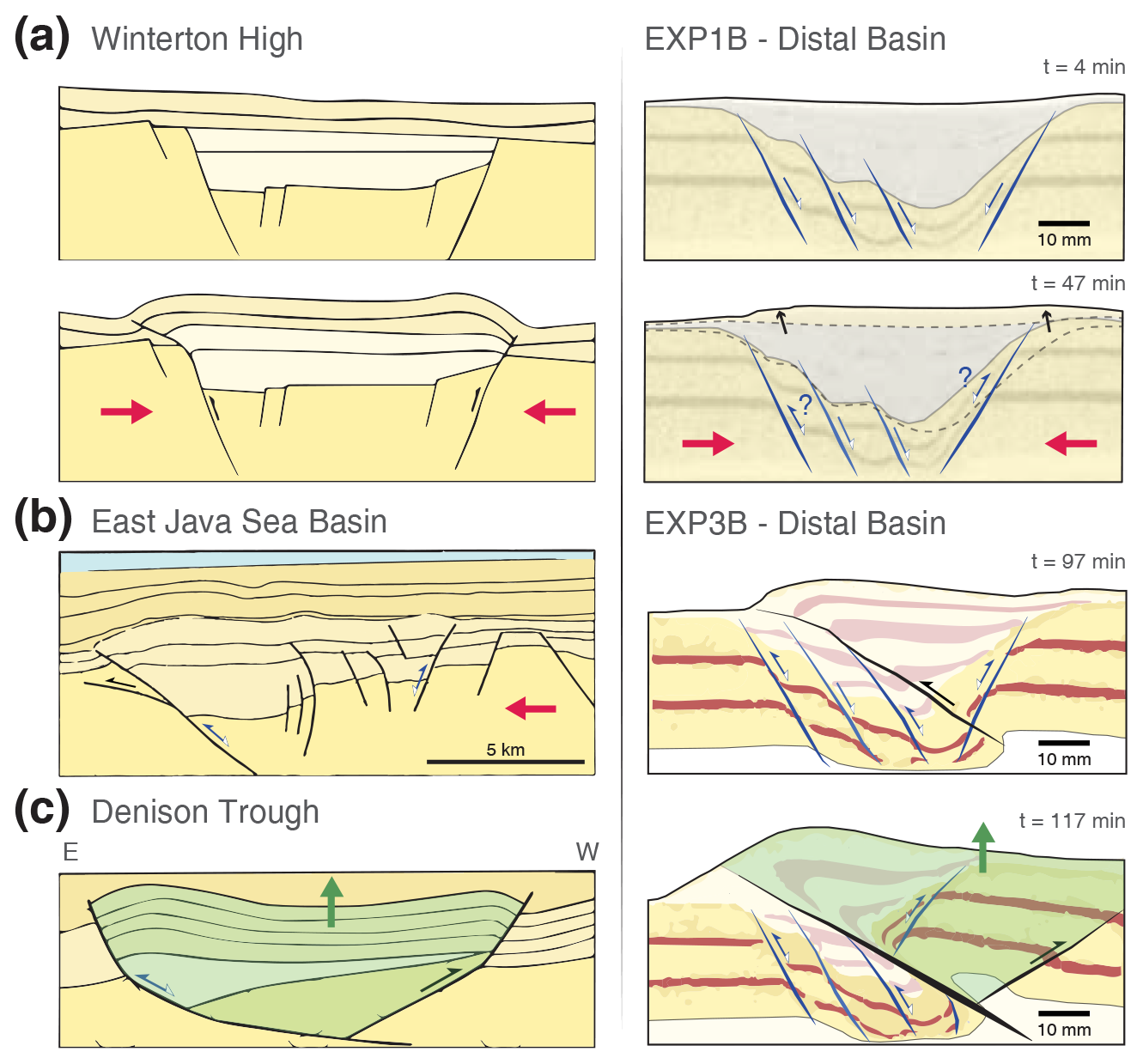
Figure 13Side-by-side comparison between selected natural examples and small-scale observations from experimental results. (a) Winterton High and EXP1B distal basin. (b) Eastern Java Sea basin and EXP3B distal basin, early stages. (c) Denison Trough and EXP3B distal basin, late stages. Red arrows indicate compressional forces. The section highlighted in green in panel (c) indicates pop-up structures being uplifted during inversion.
In natural scenarios, partially inverted grabens may also show strong asymmetry when they are closer to the emplacement of the fold-and-thrust belt, as interpreted for the eastern Java Sea basin, Southeast Asia. In this natural example, compressional forces proceeding from the north invert wedge-shaped syn-extensional strata, resulting in harpoon or arrowhead geometries (McClay, 1995). Similar structures have been identified in our models, such as in the distal basin of EXP3B, where contractional faulting localised along the weaker microbeads resulted in an asymmetric harpoon geometry (Fig. 13b). Certain areas of the eastern Java Sea basin show basin inversion due to reverse motion along the extensional listric fault (Zwaan et al., 2022). However, analysis from seismic data indicates that other inverted regions in the same basin localise compressional deformation partially via normal fault reactivation and partially via new frontal thrusts that originate in the proximity of the normal faults (McClay, 1995) (Fig. 13b). This pattern is also observed in our experiments; the unfavourable orientation of steep normal faults prevents their contractional reactivation, but new thrusts always form in the proximity of pre-existing extensional faults.
Another expression of an inverted graben has been identified in the Denison Trough, eastern Australia (Korsch et al., 2009; Buiter et al., 2009). Previous studies have estimated an uplift along the syn-rift strata (∼ 400 m) that doubles that observed for the surrounding basement rocks (∼ 200 m) (Buiter et al., 2009), as recognised in several of the partially inverted basins in all our models (Fig. 9). In the example of the Denison Trough, the fact that not only syn-rift strata were uplifted but also a section of the crystalline basement surrounding the basin is comparable to observations from the distal basin of EXP2B. In this model, a back thrust formed in line with the rift boundary faults, while a new frontal thrust originated at the same location from the detachment layer but propagated towards the surface along the quartz sand layer (i.e. proxy for crystalline basement) instead (Fig. 13b). Whether it is the forward or backward thrust that reactivates border-normal faults remains difficult to predict. Still, from our models we can suggest the following boundary conditions that may lean towards one or the other: (a) occurrence of a single extensional basin tends to always localise the frontal thrust along the foreland-most border-normal fault and (b) when multiple extensional basins are present in the foreland, the distance between them will be the factor controlling how each basin will be inverted. The longer the distance between the basins, the higher the probability of observing frontal thrust localisation along the foreland-most normal faults.
We draw the following conclusions from our series of analogue experiments investigating the inversion of multiple basins in foreland fold-and-thrust belts:
-
Extensional basins proximal to the orogenic front tend to strongly localise shortening, with frontal thrusts developing along weak basin and provoking its contraction and uplift very early in the shortening stage.
-
Extensional basins will act as efficient stress localisers and will prevent stress transfer beyond their location; no thrusts form beyond their position until very advanced stages of deformation, in which the wedge taper angle gets too high, and the system counteracts such instability by forming a new frontal thrust beyond the extensional basin.
-
The presence of extensional basins seems to slightly increase the value of the critical wedge taper angle, possibly associated with longer periods of thrust localisation along the weak basins. Heterogeneities in terms of physical properties in the interior of the wedge do not seem to substantially affect the overall evolution of deformation.
-
Inversion of basins located between the other two basins tends to be short-lived, as its brittleness is strongly dependent on the amount of overburden and/or prograding thrust sheets, which hinder the inversion of extensional structures by increasing the vertical principal stress (σ3)
-
The degree and type of inversion of extensional basins depends on both the relative location and distance to the orogenic front and the presence of another extensional basin between a given basin and the orogenic front.
-
Extensional basins located at large distances from the indenter show early evidence of inversion, as interpreted in nature. While EXP1B showed the maximum values of average cumulative strain within the basin prior to its failure by shortening, we cannot extrapolate our observations to nature because the amount of inversion will also depend on factors such as the degree of interplate coupling and on the structural, thermal, and/or compositional conditions of the lithosphere, variables that are not modelled here. Although we cannot define a threshold distance or define the nature of the basin inversion for distal extensional basins in the foreland of fold-and-thrust belts, our analogue models provide conceptual models for comparison with natural examples.
Images, videos, and selected raw PIV-exported files are freely available as a data publication deposited in the GFZ Data Services database (https://doi.org/10.5880/fidgeo.2023.011, Molnar and Buiter, 2023).
NM and SB planned and developed the experimental plan. NM performed the experiments, and NM and SB analysed and interpreted the model results. NM wrote the initial manuscript draft, then both NM and SB reviewed and edited the manuscript.
At least one of the (co-)authors is a member of the editorial board of Solid Earth. The peer-review process was guided by an independent editor, and the authors also have no other competing interests to declare.
Publisher's note: Copernicus Publications remains neutral with regard to jurisdictional claims in published maps and institutional affiliations.
This article is part of the special issue “Analogue modelling of basin inversion”. It is not associated with a conference.
We would like to thank Werner Kraus for his endless support in the laboratory and to Lina Gotzen and Jan Wagner for their invaluable assistance during laboratory experiments and for the fruitful discussions when analysing the results. Pablo Granado and Daniele Maestrelli are sincerely thanked for their constructive comments that helped improve the manuscript considerably.
This paper was edited by Riccardo Reitano and reviewed by Daniele Maestrelli and Pablo Granado.
Badley, M. E., Price, J. D., and Backshall, L. C.: Inversion, reactivated faults and related structures: seismic examples from the southern North Sea, Geol. Soc. Spec. Publ., 44, 201–219, https://doi.org/10.1144/GSL.SP.1989.044.01.12, 1989.
Bally, A. W.: Tectogénèse et sismique réflexion, B. Soc. Geol. Fr., 29, 279–285, 1984.
Beauchamp, W., Allmendinger, R .W., Barazangi, M., Demnatie, A., El Alji, M., and Dahmani, M.: Inversion tectonics and the evolution of the High Atlas Mountains, Morocco, based on a geological–geophysical transect, Tectonics, 19, 163–184, 1999.
Bonini, M., Sani, F., and Antonielli, B.: Basin inversion and contractional reactivation of inherited normal faults: A review based on previous and new experimental models, Tectonophysics, 522–523, 55–88, https://doi.org/10.1016/j.tecto.2011.11.014, 2012.
Bosworth, W. and Tari, G.: Hydrocarbon accumulation in basins with multiple phases of extension and inversion: examples from the Western Desert (Egypt) and the western Black Sea, Solid Earth, 12, 59–77, https://doi.org/10.5194/se-12-59-2021, 2021.
Bracène R. and de Lamotte D. F.: The origin of intraplate deformation in the Atlas system of western and central Algeria: from Jurassic rifting to Cenozoic–Quaternary inversion, Tectonophysics, 357, 207–226, https://doi.org/10.1016/S0040-1951(02)00369-4, 2002.
Brewer, J. A. and Turcotte, D. L.: On the stress system that formed the Laramide Wind River Mountains, Wyoming, Geophys. Res. Lett., 7, 449–452, https://doi.org/10.1029/GL007i006p00449, 1980.
Brun, J. P.: Narrow rifts versus wide rifts: inferences for the mechanics of rifting from laboratory experiments, Philos. T. R. Soc. Lond., 357, 695–712, 1999.
Brun, J. P. and Nalpas, T.: Graben inversion in nature and experiments, Tectonics, 15, 677–687, https://doi.org/10.3969/j.issn.1008-0589.2016.04.07, 1996.
Buchanan, P. G. and McClay, K. R.: Sandbox experiments of inverted listric and planar fault systems, in: Experimental and Numerical Modelling of Continental Deformation, edited by: Cobbold, P. R., Tectonophysics, 188, 97–115, 1991.
Buck, W. R.: Modes of continental lithospheric extension, J. Geophys. Res., 96, 20161, https://doi.org/10.1029/91JB01485, 1991.
Buiter, S. J. H.: A review of brittle compressional wedge models, Tectonophysics, 530–531, 1–17, https://doi.org/10.1016/j.tecto.2011.12.018, 2012.
Buiter, S. J. H., Pfiffner, O. A., and Beaumont, C.: Inversion of extensional sedimentary basins: A numerical evaluation of the localisation of shortening, Earth Planet. Sci. Lett., 288, 492–504, https://doi.org/10.1016/j.epsl.2009.10.011, 2009.
Butler, R. and Bond, C.: Thrust systems and contractional tectonics, chap. 9, Regional Geology and Tectonics, edited by: Scarselli, N., Adam, J., Chiarella, D., Roberts, D. G., and Bally, A. W., 2nd Edn., Elsevier, 149–167, https://doi.org/10.1016/B978-0-444-64134-2.00008-0, 2020.
Butler, R. W. H.: The influence of pre-existing basin structure on thrust system evolution in the western Alps, in: Inversion Tectonics, edited by: Cooper, M. A. and Williams, G. D., Spec. Publ. Geol. Soc., 44, 105–122, https://doi.org/10.1144/GSL.SP.1989.044.01.0, 1989.
Chadwick, R. A.: Aspects of basin inversion in southern Britain, J. Geol. Soc., 150, 311–322, https://doi.org/10.1144/gsjgs.150.2.0311, 1993.
Cooper, M. and Warren, M. J.: Inverted fault systems and inversion tectonic settings, in: Regional Geology and Tectonics, 2nd Edn., Elsevier, 169–204, https://doi.org/10.1016/b978-0-444-64134-2.00009-2, 2020.
Cooper, M. A. and Williams, G. D. (Eds.): Inversion tectonics, Geological Society, London, UK, Geol. Soc. Spec. Publ. 44, 1485, 375 pp., https://doi.org/10.1144/GSL.SP.1989.044.01.25, 1989.
Coulomb, C. A.: Sur l'application des régles de maximis et minimis à quelques problèmes de statique, relatifs à l'architecture, Acad. R. Sci. Paris Mem. Math. Phys., 7, 343–382, 1773.
Coward, M. P.: Inversion tectonics, in: Continental Deformation, edited by: Hancock, P. L., Pergamon Press, Oxford, 289–304, ISBN 0080379303, 1994.
Cubas, N., Barnes C., and Maillot B.: Inverse method applied to a sand wedge: Estimation of friction parameters and uncertainty analysis, J. Struct. Geol., 55, 101–113, https://doi.org/10.1016/j.jsg.2013.07.003, 2013.
Dahlen, F. A.: Noncohesive Critical Coulomb Wedges: an Exact Solution., J. Geophys. Res., 89, 10125–10133, https://doi.org/10.1029/JB089iB12p10125, 1984.
Dahlen, F. A.: Critical taper model of fold-and-thrust belts and accretionary wedges, Annu. Rev. Earth Pl. Sc., 18, 55–99, https://doi.org/10.1146/annurev.earth.18.1.55, 1990.
Delvaux, D.,: Tectonic and palaeostress evolution of the Tanganyika-Rukwa-Malawi rift segment, East African Rift System, in: Peri-Tethys Memoir 6: Peri- Tethyan Rift/Wrench Basins and Passive Margins, edited by: Ziegler, P. A., Cavazza, W., Robertson, A. H. F., and Crasquin-Soleau, S., Mem. Mus. natn. Hist. nat., Paris, 186, 545–567, ISBN 2-85653-528-3, 2001.
Del Ventisette, C., Montanari, D., Sani, F., and Bonini, M.: Basin inversion and fault reactivation in laboratory experiments, J. Struct. Geol., 28, 2067–2083, https://doi.org/10.1016/j.jsg.2006.07.012, 2006.
Di Domenica, A., Bonini, L., Calamita, F., Toscani, G., Galuppo, C., and Seno, S.: Analogue modeling of positive inversion tectonics along differently oriented pre-thrusting normal faults: An application to the Central-Northern Apennines of Italy, Bull. Geol. Soc. Am., 126, 943–955, https://doi.org/10.1130/B31001.1, 2014.
England, P.: Constraints on extension of continental lithosphere, J. Geophys. Res., 88, 1145, https://doi.org/10.1029/JB088iB02p01145, 1983.
Gillcrist, R., Coward, M., and Mugnier, J. L.: Structural inversion and its controls: examples from the Alpine foreland and the French Alps, Geodin. Acta, 1, 5–34, 1987.
Gottron, D.: The influence of basement structure on the geometry of fold-thrust-belts – an analog modelling study, MSc Thesis, RWTH Aachen University, Aachen, Germany, 2018.
Granado, P. and Ruh, J. B.: Numerical modelling of inversion tectonics in fold-and-thrust belts, Tectonophysics, 763, 14–29, https://doi.org/10.1016/j.tecto.2019.04.033, 2019.
Granado, P., Ferrer, O., Muñoz, J. A., Thöny, W., and Strauss, P.: Basin inversion in tectonic wedges: Insights from analogue modelling and the Alpine-Carpathian fold-and-thrust belt, Tectonophysics, 703–704, 50–68, https://doi.org/10.1016/j.tecto.2017.02.022, 2017.
Granado, P., Tavani, S., Carrera, N., and Muñoz, J. A.: Deformation pattern around the Conejera fault blocks (Asturian Basin, North Iberian Margin), Geol. Acta, 16, 357–373, https://doi.org/10.1344/GeologicaActa2018.16.4.2, 2018.
Granado, P., Ruh J. B., Santolaria P., Strauss P., and Muñoz J. A.: Stretching and Contraction of Extensional Basins With Pre-Rift Salt: A Numerical Modeling Approach, Front. Earth. Sci., 9, https://doi.org/10.3389/feart.2021.648937, 2021.
Guiraud, R. and Bosworth, W.: Senonian basin inversion and rejuvenation of rifting in Africa and Arabia: synthesis and implications to plate-scale tectonics, Tectonophysics, 282, 39–82, https://doi.org/10.1016/S0040-1951(97)00212-6, 1997.
Guiraud, R. and Maurin, J. C.: Early Cretaceous rifts of Western and Central Africa: an overview, Tectonophysics, 213, 153–168, https://doi.org/10.1016/0040-1951(92)90256-6, 1992.
Handin, J.: On the Coulomb-Mohr failure criterion, J. Geophys. Res., 74, 5343, https://doi.org/10.1029/JB074i022p05343, 1969.
Hansen, T. H., Clausen, O. R., and Andresen, K. J.: Thick- and thin-skinned basin inversion in the Danish Central Graben, North Sea – the role of deep evaporites and basement kinematics, Solid Earth, 12, 1719–1747, https://doi.org/10.5194/se-12-1719-2021, 2021.
Hubbert, M. K.: Theory of scale models as applied to the study of geologic structures, Geol. Soc. Am. Bull., 48, 1459–1520, https://doi.org/10.1130/GSAB-48-1459, 1937.
Jackson, J.: Reactivation of basement faults and crustal shortening in orogenic belts, Nature, 283, 343–346, https://doi.org/10.1038/283343a0, 1980.
Jaeger, J. C. and Cook, N. G. W.: Fundamentals of Rock Mechanics. Chapman and Hall, Wiley, New York, 585 pp., ISBN 978-0-632-05759-7, 1976.
Jagger, L. J. and McClay, K. R.: Analogue modelling of inverted domino-style basement fault systems, Basin Res., 30, 363–381, https://doi.org/10.1111/bre.12224, 2018.
Jara, P., Likerman, J., Charrier, R., Herrera, S., Pinto, L., Villarroel, M., and Winocur, D.: Closure type effects on the structural pattern of an inverted extensional basin of variable width: Results from analogue models, J. South Am. Earth Sci., 87, 157–173, https://doi.org/10.1016/j.jsames.2017.10.018, 2018.
Kley, J.: Timing and spatial patterns of Cretaceous and Cenozoic inversion in the Southern Permian Basin, Geol. Soc. Spec. Publ., 469, 19–31, https://doi.org/10.1144/SP469.12, 2018.
Klinkmüller, M., Rosenau, M., and Kemnitz, H.: Properties of granular analogue model materials: A community wide survey, Tectonophysics, 684, 23–38, https://doi.org/10.1016/j.tecto.2016.01.017, 2016.
Korsch, R. J., Totterdell, J. M., Cathro, D. L., and Nicoll, M. G.: Early Permian East Australian Rift System, Aust. J. Earth Sci., 56, 381–400, 2009.
Koyi, H.: Analogue modelling: From a qualitative to a quantitative technique – A historical outline, J. Petrol. Geol., 20, 223–238, 1997.
Krantz, R. W.: Measurements of friction coefficients and cohesion for faulting and fault reactivation in laboratory models using sand and sand mixtures, Tectonophysics, 188, 203–207, https://doi.org/10.1016/0040-1951(91)90323-K, 1991.
Krzywiec, P., Kufrasa, M., Poprawa, P., Mazur, S., Koperska, M., and Ślemp, P.: Together but separate: decoupled Variscan (late Carboniferous) and Alpine (Late Cretaceous–Paleogene) inversion tectonics in NW Poland, Solid Earth, 13, 639–658, https://doi.org/10.5194/se-13-639-2022, 2022.
Lacombe, O. and Bellahsen, N.: Thick-skinned tectonics and basement-involved fold-thrust belts. Insights from selected Cenozoic orogens, Geol. Mag., 153, 763–810, 2016.
Likerman, J., Burlando, J. F., Cristallini, E. O., and Ghiglione, M. C.: Along-strike structural variations in the Southern Patagonian Andes: Insights from physical modelling, Tectonophysics, 590, 106–120, https://doi.org/10.1016/j.tecto.2013.01.018, 2013.
López, C., Del Ventisette, C., Bonini, M., Montanari, D., Maestrelli, D., Martínez, F., González R., Riquelme, R., Montenegro, D., Muñoz, B., and Guzmán‐Marusic, G.: The Relationship Between Inverted Normal Faults and Pure Thrusting During the Tectonic Inversion of the Domeyko Cordillera, Northern Chile: Structural and Seismic Interpretation and Analogue Modelling Experiments, Tectonics, 41, 12, https://doi.org/10.1029/2022TC007378, 2022.
Maillot, B.: A sedimentation device to produce uniform sand packs, Tectonophysics, 593, 85–94, https://doi.org/10.1016/j.tecto.2013.02.028, 2013.
Mattauer, M., Tapponnier, P., and Proust, F.: Sur les mécanismes de formation des chaînes intracontinentales: l'exemple des chaînes atlasiques du Maroc, Bull. Soc. Géol. France, 521–526, https://doi.org/10.2113/gssgfbull.S7-XIX.3.521, 1977.
McClay, K. R.: The geometries and kinematics of inverted fault systems: A review of analogue model studies, Geol. Soc. Spec. Publ., 88, 97–118, https://doi.org/10.1144/GSL.SP.1995.088.01.07, 1995.
McClay, K. R.: Recent advances in analogue modelling: Uses in section interpretation and validation, Geol. Soc. Spec. Publ., 99, 201–225, https://doi.org/10.1144/GSL.SP.1996.099.01.16, 1996.
Molnar, N. and Buiter, S.: Analogue modelling of the inversion of multiple extensional basins in foreland fold-and-thrust belts: PIV-processed dataset and experiment evolution videos, GFZ Data Services [data set], https://doi.org/10.5880/fidgeo.2023.011, 2023.
Nalpas, T., Le Douaran, S., Brun, J. P., Unternehr, P., and Richert, J. P.: Inversion of the Broad Fourteens Basin (offshore Netherlands), a small-scale model investigation, Sediment. Geol., 95, 237–250, https://doi.org/10.1016/0037-0738(94)00113-9, 1995.
Panien, M., Schreurs, G., and Pfiffner, A.: Sandbox experiments on basin inversion: Testing the influence of basin orientation and basin fill, J. Struct. Geol., 27, 433–445, https://doi.org/10.1016/j.jsg.2004.11.001, 2005.
Panien, M., Buiter, S. J. H., Schreurs, G., and Pfiffner, O. A.: Inversion of a symmetric basin: Insights from a comparison between analogue and numerical experiments, Geol. Soc. Spec. Publ., 253, 253–270, https://doi.org/10.1144/GSL.SP.2006.253.01.13, 2006.
Pfiffner, O. A.: Geologie der Alpen, Haupt Verlag/UTB, Bern-Stuttgart-Wien, 360 pp., ISBN 9783825286101, 2009.
Phillips, T. B., Jackson, C. A.-L., Bell, R. E., and Duffy, O. B.: Oblique reactivation of lithosphere-scale lineaments controls rift physiography – the upper-crustal expression of the Sorgenfrei–Tornquist Zone, offshore southern Norway, Solid Earth, 9, 403–429, https://doi.org/10.5194/se-9-403-2018, 2018.
Picha, F. J., Stránik, Z., and Krejči, O.: Geology and Hydrocarbon Resources of the Outer Western Carpathians and Their Foreland, Czech Republic, The Carpathians and Their Foreland: Geology and Hydrocarbon Resources, American Association of Petroleum Geologists, https://doi.org/10.1306/985607m843067, 2006.
Ramberg, H.: Gravity, Deformation and the Earth's Crust, Academic Press, London, 452 pp., ISBN 9780125768603, 1981.
Ritter, M. C., Leever, K., Rosenau, M., and Oncken, O.: Scaling the sandbox – Mechanical (dis) similarities of granular materials and brittle rock, J. Geophys. Res.-Sol. Ea., 121, 6863–6879, https://doi.org/10.1002/2016JB012915, 2016.
Roca, E., Frizon de Lamotte, D., Mauffret, A., Bracène, R., Vergés, J., Benaouali, N., Fernandez, M., Munoz, J. A., Zeyen, H.: The Transmed Atlas – The Mediterranean Region from Crust to Mantle, edited by: Cavazza, W., Roure, F. M., Spakman W., Stampfli, G. M., Ziegler, P. A., Springer, Berlin, Heidelberg, ISBN 978-3-642-18919-7, 2004.
Sassi, W., Colletta, B., Balé, P., and Paquereau, T.: Modelling of structural complexity in sedimentary basins: The role of pre-existing faults in thrust tectonics, Tectonophysics, 226, 97–112, https://doi.org/10.1016/0040-1951(93)90113-X, 1993.
Scisciani, V.: Styles of positive inversion tectonics in the Central Apennines and in the Adriatic foreland: Implications for the evolution of the Apennine chain (Italy), J. Struct. Geol., 31, 1276–1294, https://doi.org/10.1016/j.jsg.2009.02.004, 2009.
Scisciani, V., Patruno, S., Tavarnelli, E., Calamita, F., Pace, P., and Iacopini, D.: Multi-phase reactivations and inversions of paleozoic–mesozoic extensional basins during the Wilson cycle: Case studies from the north sea (UK) and the northern apennines (Italy), Geol. Soc. Spec. Publ., 470, 205–243, https://doi.org/10.1144/SP470-2017-232, 2019.
Sibson, R. H.: Rupture nucleation on unfavorably oriented faults, Bull. Seismol. Soc. Am., 80, 1580–1604, https://doi.org/10.1785/BSSA08006A1580, 1990.
Souloumiac, P., Maillot, B., and Leroy, Y. M.: Bias due to side wall friction in sand box experiments, J. Struct. Geol., 35, 90–101, 2012.
Stockmal, G. S., Beaumont, C., Nguyen, M., and Lee, B.: Mechanics of thin-skinned fold- and-thrust belts: insights from numerical models, in: Whence the mountains? Inquiries into the evolution of orogenic systems, edited by: Sears, J. W., Harms, T. A., and Evenchick, C. A., Geol. S. Am. S., 433, 63–98, 2007.
Teixell, A., Arboleya, M.-L., Julivert, M., and Charroud, M.: Tectonic shortening and topography in the central High Atlas (Morocco), Tectonics, 22, 1051, https://doi.org/10.1029/2002TC001460, 2003.
Teixell, A. and Koyi, H. A.: Experimental and Field study of the effects of lithological contrasts on thrust related deformation, Tectonics, 22, 1054–1073, 2003.
Twiss, R. J. and Moores, E. M.: Structural Geology, W.H. Freeman and Company, New York, 532 pp., ISBN 9780716749516, 1992.
Vermeer, P.: Orientation of shear bands in biaxial tests, Geotechnique, 40, 223–236, 1990.
Yagupsky, D. L., Cristallini, E. O., Fantin, J., Valcarce, G., Bottesi, G., and Varade, R.: Oblique half-graben inversion of the Mesozoic Neuquén Rift in the Malargüe fold and thrust belt, Mendoza, Argentina: new insights from analogue models, J. Struct. Geol., 30, 839–853, https://doi.org/10.1016/j.jsg.2008.03.007, 2008.
Ziegler, P. A.: Geodynamic model for Alpine intra-plate compressional deformation in Western and Central Europe, Geol. Soc. Spec. Publ., 44, 63–85, https://doi.org/10.1144/GSL.SP.1989.044.01.05, 1989.
Ziegler, P. A.; Evolution of the Arctic–North Atlantic and the Western Tethys, Mem.-Am. Assoc. Pet. Geol., 43, 198 pp. and 30 plates, 1988.
Ziegler, P. A., Cloetingh, S., and van Wees, J.-D.: Dynamics of intraplate compressional deformation: the Alpine foreland and other examples, Tectonophysics, 252, 7–59, 1995.
Ziegler, P. A., van Wees, J.-D., and Cloetingh, S.: Mechanical controls on collision-related compressional intraplate deformation, Tectonophysics, 300, 103–129, 1998.
Zwaan, F., Schreurs, G., Buiter, S. J. H., Ferrer, O., Reitano, R., Rudolf, M., and Willingshofer, E.: Analogue modelling of basin inversion: a review and future perspectives, Solid Earth, 13, 1859–1905, https://doi.org/10.5194/se-13-1859-2022, 2022.