the Creative Commons Attribution 4.0 License.
the Creative Commons Attribution 4.0 License.
 | 18 Feb 2026
Seismic surveys at the Per Geijer iron oxide-apatite mineralization in Kiruna, Sweden
Niklas Juhojuntti
Łukasz Sito
The mining company LKAB currently runs an intense exploration program focused on the Per Geijer iron oxide-apatite mineralization close to the active Kiruna mine, in northern Sweden. The iron mineralization is associated with high levels of phosphorus and REEs. As a major part of the mineralization occurs at depths >500 m, various deep-probing geophysical surveys have been used to guide the exploration throughout the years, recently also including seismic measurements. An initial pilot reflection profile in 2021 showed promising results, and three additional profiles were acquired shortly afterwards. These were followed by downhole seismics (VSP) in two drill holes. During 2024 an approximately 13 km2 large 3D survey was also acquired in the area. All these surveys utilized a Vibroseis as the source of the seismic signals. Clearly distinguishable P-wave reflections appear in the shot records from the surface seismics as well as in the downhole seismics, and the latter also show interpreted P-S reflections. The iron mineralization is dipping at an angle of 50–60°, making the data processing challenging. Some of the 2D profiles cross the mineralization at an oblique angle, and out-of-the-plane reflections were confirmed via cross-dip analysis. The resulting migrated sections and volumes show prominent reflections correlating with the Per Geijer mineralization and indicating extensions beyond the drill hole coverage. Reflections are also observed from the northern end of the nearby Kiirunavaara iron ore. Sonic and density logs indicate that the main cause of the reflections from the iron mineralization is the density contrast, as the velocity contrasts are rather small. A close comparison of the downhole seismic survey with the geological model further supports the interpretation that the iron mineralization is generating seismic reflections. Also notable in both 2D and 3D surface data is a high-amplitude reflection originating from a steeply dipping structure outside the survey area, which if projected to the surface correlates with older greenstones on the footwall (western) side of the Per Geijer mineralization and the Kiirunavaara orebody.
- Article
(17122 KB) - Full-text XML
- BibTeX
- EndNote


Seismic reflection measurements have traditionally been used for hydrocarbon exploration and are now also frequently used by the mining industry both for exploration purposes and to assist mine planning (e.g. Malehmir and Bellefleur, 2009; Juhojuntti et al., 2012; Donoso et al., 2023; Hloušek et al., 2025). For deep targets, the seismic reflection method can potentially provide higher spatial resolution than any other geophysical method. However, there is ambiguity in the interpretation, as seismic reflections can be caused by various subsurface structures, for example deformation zones and lithological contacts. For generating mineral exploration targets the seismic method is therefore probably best used in combination with other techniques, such as magnetotellurics. The typical mineral exploration setting can also often have steeply dipping structures, which pose a challenge for seismic imaging.
During the recent years there has been much exploration drilling and geophysical measurements aimed towards the Per Geijer iron oxide-apatite mineralization, also referred to as Per Geijer Deep, which is associated with high levels of phosphorus and REEs. It is located close to the Kiruna mine where the Kiirunavaara orebody is being mined via subsurface caving (Malmgren et al., 2007). The Per Geijer mineralization and the hosting volcanic units dip at an angle of 50–60° and are overlain by quartzite. As a major part of the mineralization occurs at depths >500 m, various geophysical surveys have been used to assist the exploration throughout the years, recently also including seismic measurements. An earlier reflection survey showed a reflection interpreted to originate from the Kiirunavaara orebody (Jensen et al., 2012), which has a similar dip as the Per Geijer mineralization, although the host rock environment is different. Pronounced seismic reflections have also been observed in connection with the Blötberget iron mineralization in central Sweden (Pertuz et al., 2021; Hloušek et al., 2022).
The aims of the seismic surveys at the Per Geijer field were three-fold: to image the iron mineralization, detect possible unknown mineralization in the vicinity, and to map deformation structures. The survey program was initiated by a pilot reflection profile in 2021, to test the potential of the method in the Per Geijer area. As this profile showed promising results, three additional seismic profiles were acquired shortly afterwards, using higher fold and denser receiver layouts. We then carried out downhole seismics (VSP) in two drill holes. In connection with the VSP survey a small 3D grid was deployed at the surface. This small 3D survey showed promising results, and a larger 3D survey was subsequently carried out in 2024. All these data have been acquired with Vibroseis as the seismic source, except for an accelerated weight-drop source being used for some sensitive parts of the 3D survey area.
Below we outline the processing of the seismic data and describe the observed reflections. The seismic images are compared with available geological models, making the case that the iron-oxides are causing pronounced reflections and thus that the seismic reflection method can be an effective exploration tool for such deposits. We also attempt to explain the physical cause of the reflections, using sonic and density logs.
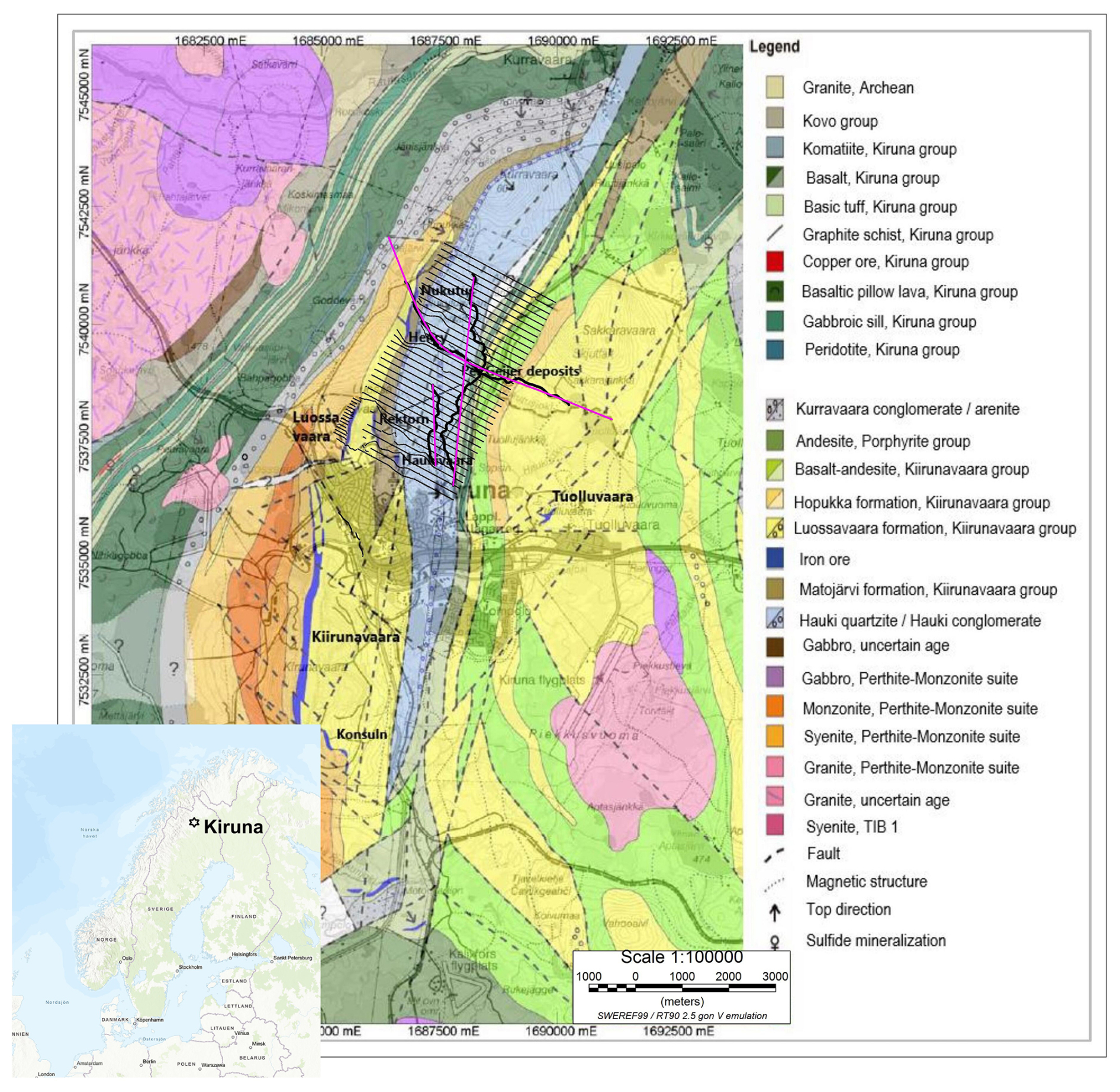
Figure 1Geology of the Kiruna area, with location of the seismic surveys. The seismic receiver points are shown in black, and the CDP projection lines for the 2D profiles in purple. The source points have been omitted. Geological map modified from Martinsson and Erlandsson (2009).
The Kiirunavaara iron oxide-apatite (IOA) orebody is the typical example of IOA mineralization (Geijer, 1919; Parák, 1975; Forsell, 1987). It has been mined continuously since the year 1902, and the current main haulage level is 1365 m below the former peak of the mountain Kiirunavaara. Much has been written about the geological setting and origin of this orebody, starting with the pioneering work by Geijer (1910). There are several other IOA deposits in the immediate surroundings, many of which have been mined at least partially. The Luossavaara orebody, which was mined until the early 1980s, is located just north of Kiirunavaara. East of the Luossavaara orebody there are several smaller deposits (Rektorn, Haukivaara, Henry and Nukutus) collectively called the Per Geijer ores, which were also mined in open pits in the early to mid-20th century. In the 1960's a long-wavelength magnetic anomaly just north of Kiruna town led to the discovery of the Per Geijer Deep mineralization (PG Deep), which is the down-dip expression of the surficial Per Geijer mineralization and the main target for the seismic surveys discussed in this article.
The Kiirunavaara, Luossavaara and PG Deep IOA deposits are all roughly disc-shaped bodies, striking approximately north-south and dipping 50–60° to the east (Figs. 1 and 2). The Kiirunavaara orebody is about 4 km long and on average 80 m thick, increasing to about 200 m in the north. The iron oxides in Kiirunavaara and Luossavaara are almost exclusively magnetite, whereas the PG Deep mineralization is a mix of magnetite and hematite. PG Deep is associated with significant amounts of phosphorus and REE's (LKAB, 2024).
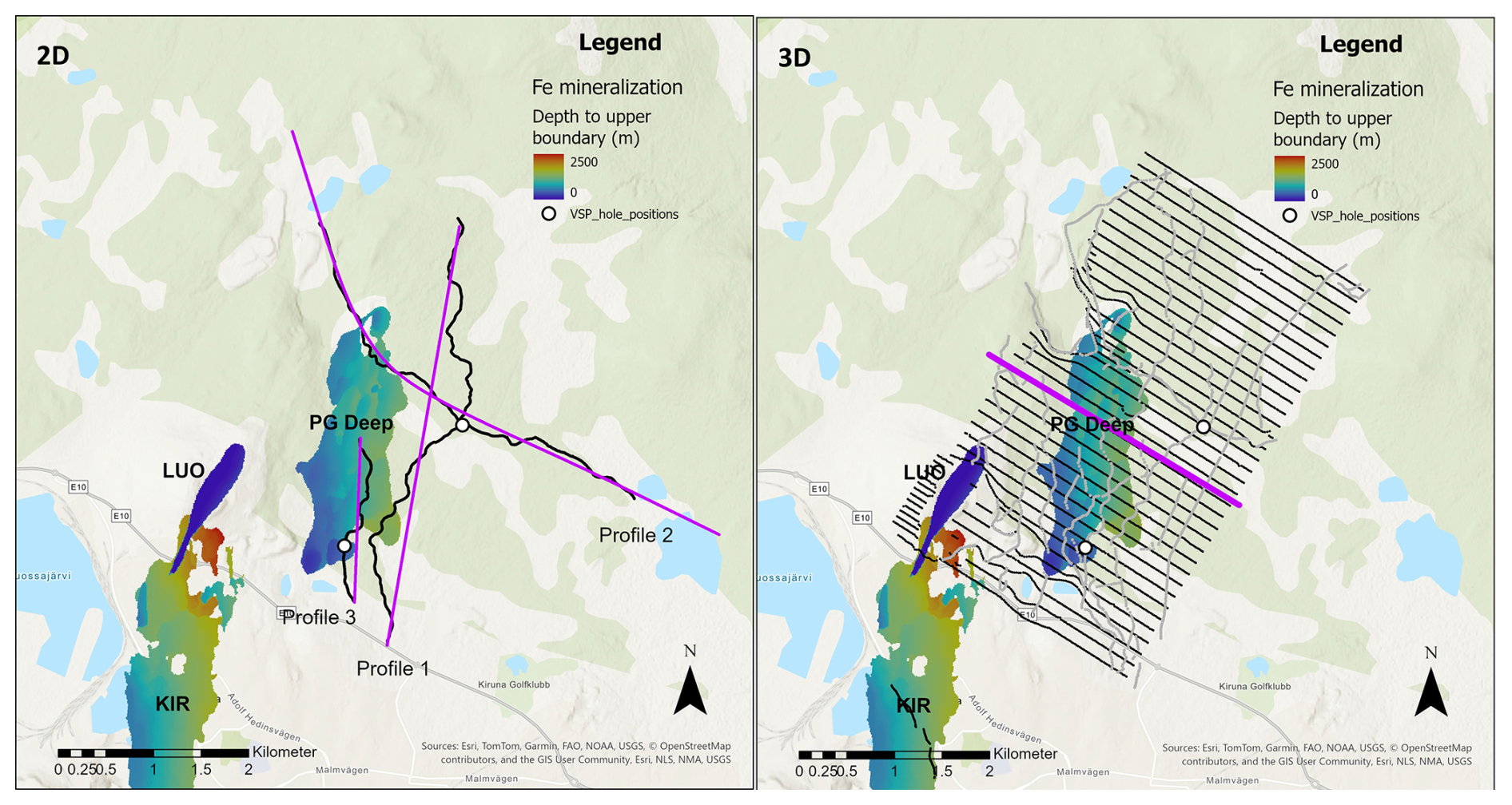
Figure 2The seismic surveys in comparison with the iron-oxide deposits in the Kiruna area, colored by the depth to the upper boundary: KIR – Kiirunavaara, LUO – Luossavaara, PG Deep – Per Geijer Deep. Black symbols show receivers and grey symbols source points. For the 2D surveys, the source points overlap with the receivers. The purple symbols show CDP projection lines and the inline selected for display in Fig. 8. The two VSP holes are also shown. Background map credits: Esri, TomTom, Garmin, FAO, NOAA, USGS, NLS, NMA.
The Kiruna area is divided in two major volcanosedimentary belts with different ages that show a younging direction from west to east, dipping approximately 50–60° towards east (Fig. 1). In the west the bedrock consists of the early Paleoproterozoic Kiruna greenstone belt, which mainly comprises mafic volcanic rocks, gabbroic units and graphite schist. The Kiruna greenstone belt is clearly visible in gravity and electromagnetic surveys. The overlying Kurravaara conglomerate unit separates the younger Kiirunavaara group from the greenstones. The IOA deposits in the Kiruna area are located within the volcanic and volcano-sedimentary formations of the Kiirunavaara Group (Fig. 1). The Kiirunavaara group starts with the trachyandesitic Hopukka Formation that forms the footwall of the Kiirunavaara and Luossavaara orebodies. The hanging wall consists of the rhyolitic-rhyodacitic Luossavaara Formation. The PG mineralization is located between the volcanic Luossavaara Formation and the overlying volcano-sedimentary Matojärvi Formation. Mineralization can also occur exclusively within the Luossavaara Formation or in the Matojärvi Formation. The Matojärvi Formation is a complex volcano-sedimentary sequence that hosts hematite-dominant and mixed hematite-magnetite mineralization, commonly seen to replace the host lithologies. It is covered by a slightly metamorphosed, thick, sedimentary basin-derived package (quartzites, conglomerates and phyllites of the Hauki Formation). The Hauki Formation has very low magnetization and very low electrical conductivity.
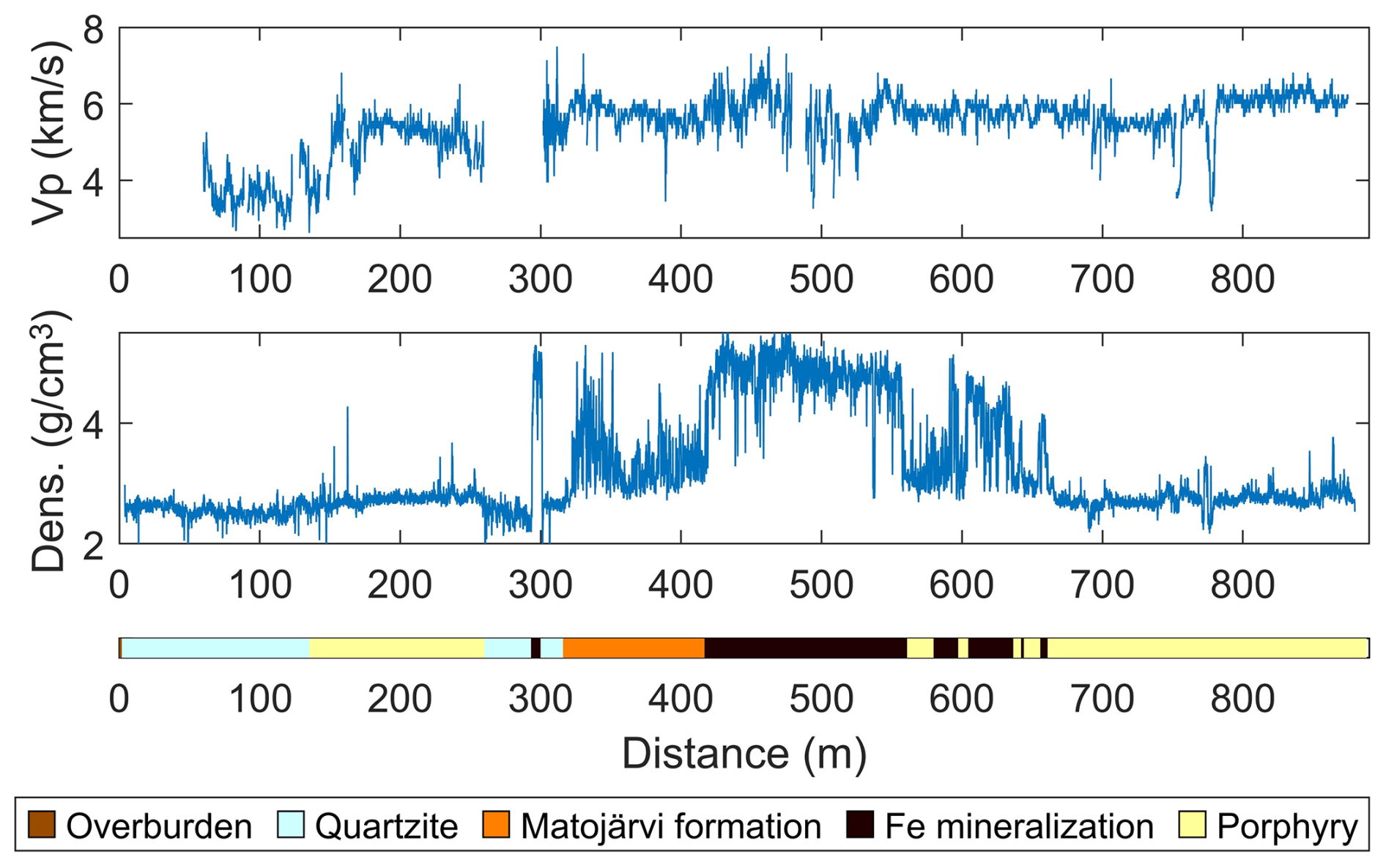
Figure 3Wireline logs from one drill hole intersecting the Per Geijer Deep iron mineralization. The lithology description has been simplified.
Sonic and density logging have been carried out in selected exploration holes drilled in the Per Geijer area, and one logging example is shown in Fig. 3. There is a distinct density increase in the Fe mineralization, as expected. The Matojärvi formation overlying the mineralization also has intervals with high density. The quartzite and porphyry intervals have significantly lower densities. The P-wave velocity was difficult to measure in the shallow part of the hole. However, it appears to be around 4 km s−1 in the quartzite unit, increasing to about 5.5 km s−1 in the porphyry. At the onset of the Matojärvi formation (at about 300 m) the velocity increases to around 6 km s−1. It is difficult to see any distinct change in the P-wave velocity associated with the iron-oxide mineralization, although there is an interval with somewhat higher velocity around 450 m depth, within the mineralization. It was difficult to measure reliable S-wave velocities in this drill hole, and these are not shown here. However, where it was possible to measure the S-wave velocity with some degree of accuracy, the Vp to Vs ratio is around 1.8. Note that the drill hole shown in this example (Fig. 3) predominantly encountered hematite mineralization. For comparison, Malmgren et al (2007) report P-wave velocities in the range 5.8–6.2 km s−1 for undisturbed magnetite iron ore in the Kiruna mine. Measurements on magnetite core samples from the Kiruna area show average P-wave velocities of around 6.2 km s−1, although there is considerable variation around this value.
4.1 Surface and downhole seismic data acquisition
Seismic data have been recorded along three 2D profiles covering the Per Geijer Deep mineralization, and in one 3D survey overlapping with these (Fig. 2). Downhole seismic data (walkaway VSP) were also acquired in two drill holes. While running the downhole surveys, a small 3D receiver grid was deployed at the surface, recording the signals used for the downhole seismics. This smaller 3D survey is not included in this paper, although it was a catalyst for proceeding with the larger 3D survey.
The same Mark IV Vibroseis source has been used for all seismic surveys, including the walkaway-VSP. For the larger 3D survey, we also used an accelerated weight-drop source in some sensitive areas, although these data have been processed separately and are not included in this study. The signal strength of the weight-drop source was significantly lower than for the Vibroseis truck.
It was necessary to use existing trails and roads for the Vibroseis truck (and the accelerated weight-drop), which was a particularly limiting factor for the 2D surveys. The north-south oriented Profile 1 and 3 are also almost parallel to geologic strike, which is not ideal for interpreting the data. For the 2D surveys a combination of WiNG and GS-One 10 Hz sensors were used, and the station spacing varied between 5 and 10 m. Profile 2 was acquired in two campaigns using different recording parameters, which is reflected in the variable fold.
The 3D survey was acquired with a regular grid of approximately east-west oriented receiver lines, with inline receiver spacing of 20 m and crossline receiver spacing of 140 m. Stryde sensors were used for this grid. The source lines were oriented roughly perpendicular to the receiver lines. Difficult terrain access prevented us from extending the 3D survey further to the east, which could have allowed better imaging of the PG Deep mineralization. During the 3D survey the Vibroseis force was reduced to 50 % of full strength along some roads (from the nominal 75 %). A small receiver layout of WiNG nodes was also placed close to the Kiruna mine (Fig. 2), to investigate the noise conditions in this area and to attempt recording wide-angle reflections from mineralization between Per Geijer and Kiirunavaara (using the 3D survey source points). These data were rather noisy and are not discussed further in the paper, although it is possible to detect P-wave energy in many of the shot records. All coordinates were measured using RTK GNSS receivers, and quality checked.
Walkaway VSP measurements were carried out for two holes (Fig. 2). The data were acquired using fiberoptic cables and with the same Vibroseis truck as used for the surface measurements. The source points were located along the same roads as used for Profiles 1 and 2 (Fig. 2). We employed straight fiberoptic cables, which therefore only sensed axial motion. It was not possible to cement the cables in place. However, as the holes are angled, gravity and friction should give some coupling to the borehole wall. It should also be noted that the holes were water-filled, although water will not give adequate shear contact with the media. We here focus on the survey from the northern hole, as the data from the southern hole were more noisy, possibly due to water flow from a fracture zone crossing the hole.
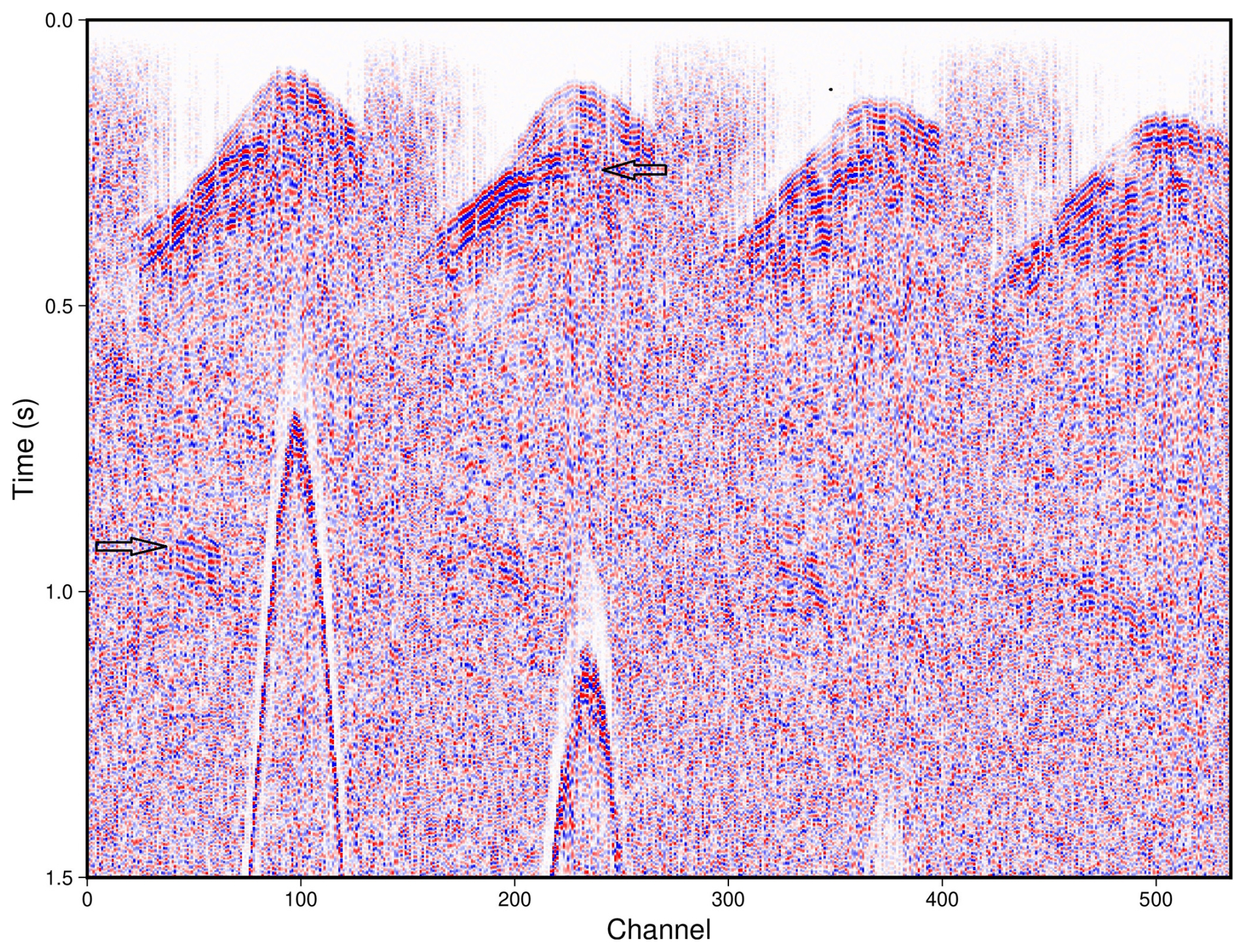
Figure 4Example shot record data, from the 3D survey. The image only shows a subset of channels. Automatic gain control and frequency filtering has been applied prior to plotting. Arrows mark the reflections discussed in the text.
4.2 Surface seismics data processing and analysis
Reflections can be observed in many of the shot records. Note for example a prominent reflection at about 0.2–0.3 s in a typical shot record from the 3D survey (Fig. 4). The record also shows a reflection at roughly 1.0–1.5 s, apparently from some steeply dipping structure. In addition, some shot records show a prominent reflection at about 2 s, again from a dipping structure.
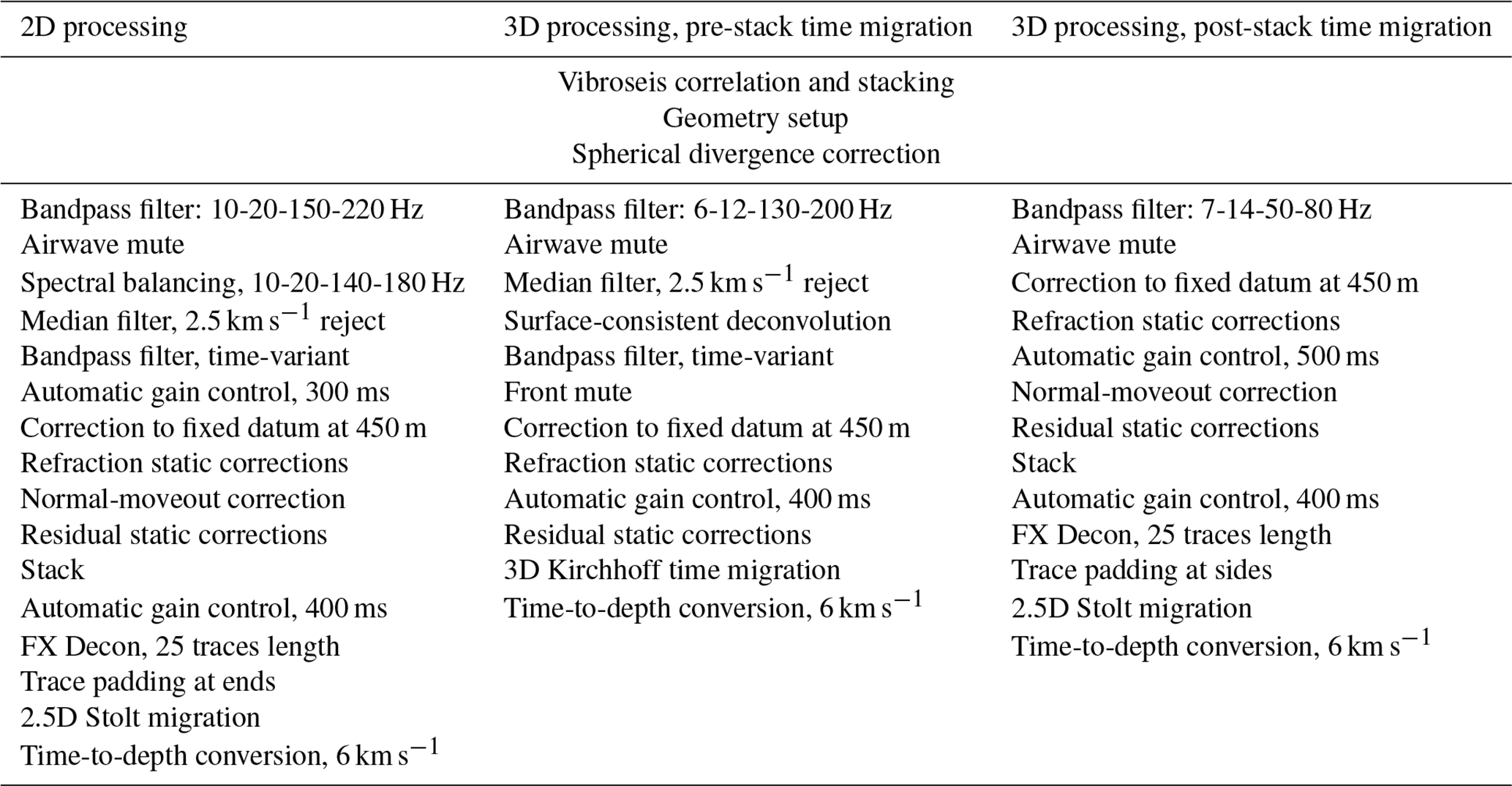
We have relied on conventional algorithms for the data processing, and the processing steps are summarized in Table A1 in the Appendix. Similar pre-stack processing sequences have been applied for all the 2D profiles, followed by post-stack migration and depth-conversion to generate the seismic images. For the 3D dataset, two different processing approaches were used, one based on pre-stack time migration and filters with wider bandwidth, the other based on post-stack migration and lower frequencies. The first approach was focused on imaging the main target of the survey, the Per Geijer Deep mineralization, with as high resolution as possible. The second 3D processing approach was aimed at imaging deeper targets using lower resolution, using a more simplified processing flow less likely to generate artefacts. CPU limitations put constraints on the maximum size of the image volumes for the pre-stack migration.
Overall, the seismic data show pronounced static shifts, as evident from the first arrivals and the reflections. Refraction static corrections have therefore been an integral part of the processing flow. For all datasets, the refraction statics have been calculated based on velocity models with two layers, the first layer representing the overburden at a fixed velocity, the second layer representing the bedrock with smooth velocity variations allowed. The first breaks were picked automatically, and quality-checked by comparing with manual picks for selected shot records. Residual reflection statics were also used to further remove short-wavelength static shifts. All surface seismic data have been processed to a fixed datum of +450 m relative to sea-level.
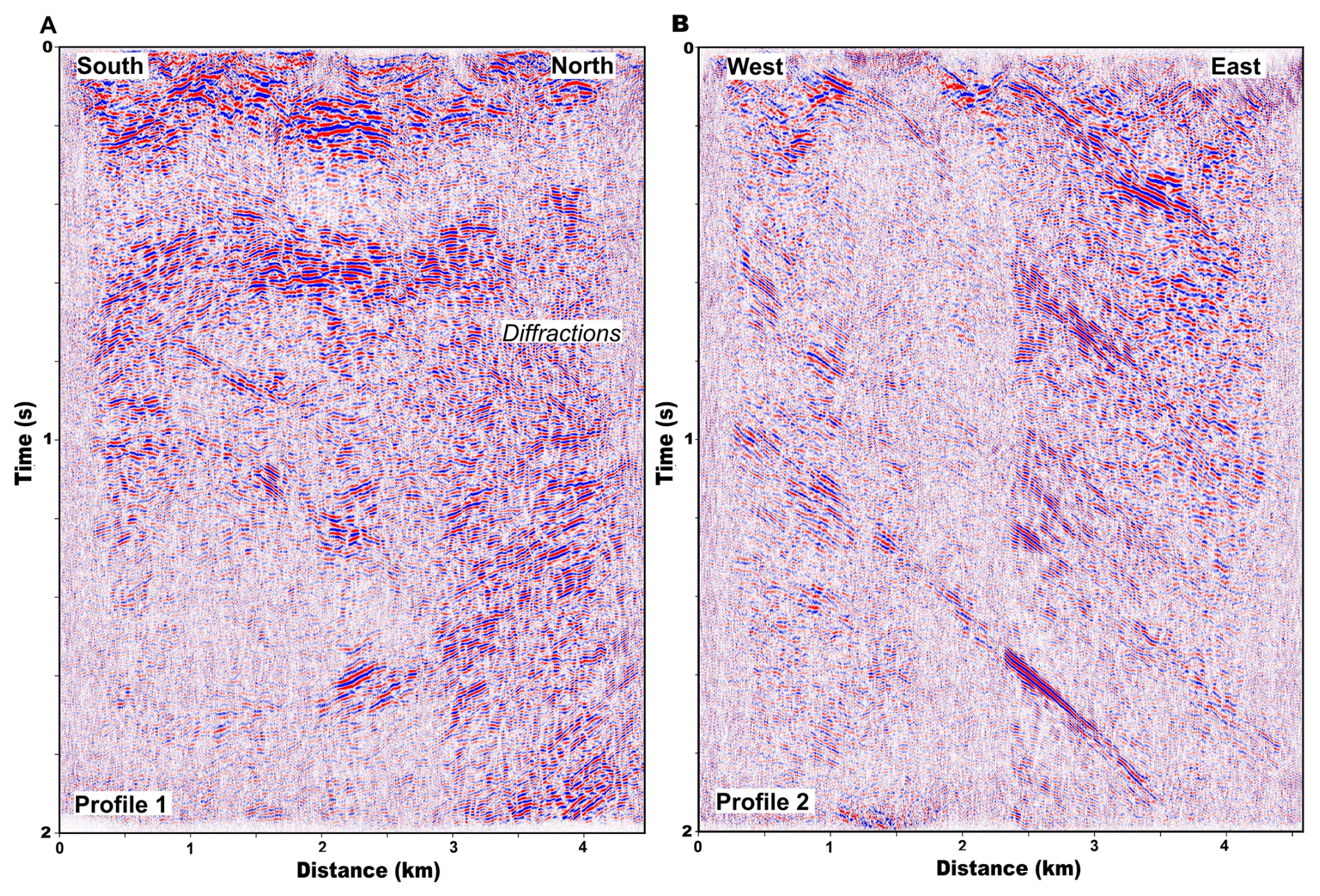
Figure 5(A) Stacked time section from Profile 1. (B) Stacked time section from Profile 2. The change in reflection character at about 2.4 km along Profile 2 is caused by a change in the stacking fold.
Surface-consistent deconvolution (Cary and Lorentz, 1993) was used for the 3D data prior to pre-stack time migration, mostly to improve waveform consistency, although it will also compress the waveform to some degree. For the 2D profiles, spectral equalization was used instead. These spectral adjustments were followed by time-varying bandpass filters, with gradually decreasing filter frequencies towards later times to account for the loss of high frequencies due to attenuation. For the second 3D processing approach which included post-stack migration and was aimed at deeper structures, no spectral adjustments or time-varying filters were used.
For the 2D profiles, CDP stacking followed by post-stack migration was used, although it was challenging to find the proper NMO velocity functions. Many of the reflections come from steeply dipping structures, and to stack these optimally very high NMO velocities would need to be used, which is not ideal for the reflections from moderately dipping structures. The chosen stacking velocities were a compromise, higher than required for sub-horizontal reflections, while not as high as would have been optimal for the steeply dipping events. Dip-moveout correction was tested but deemed not to give satisfactory results.
The stacked time sections from the 2D profiles show pronounced reflections, which in general are steeply dipping along Profile 2 (Fig. 5B), and appear more moderately dipping or sub-horizontal along Profile 1 (Fig. 5A) and Profile 3. The less pronounced apparent dip along the two latter profiles is mainly due to these profiles being oriented parallel to geologic strike. Note for example the gently dipping or sub-horizontal band of reflections at about 0.2 and 0.5 s along Profile 1 (Fig. 5A). Diffractions are also visible at the northern end of Profile 1 (Fig. 5A). Note that the fold is varying much along Profile 2, which is clearly noticeable in the stacked time section (Fig. 5B).
The reflections along Profiles 1 and 3 are probably largely coming from out of the plane, considering that most structures in the area are dipping to the east. To evaluate the direction of the incoming seismic reflections, cross-dip analysis was carried out following the procedure of Wu et al. (1995). This method makes use of the crooked recording geometry of the lines and is in a strict sense only valid for zero-offset reflections. It should nevertheless give indications of possible out-of-the-plane reflectivity also when there is considerable shot-receiver separation, as for these data. The method involves choosing a set of cross-dip angles, calculating pre-stack time shifts for these, and visually observing which of these angles maximizes the amplitude of a particular reflection in the stacked section. The example shown for Profile 3 indicates that much of the reflected energy is coming from structures dipping to the east and located to the west of profile (Fig. 6). The reflections denoted R1 and R3 have higher amplitude and appear most coherent when using a cross-dip of 30° to the east. However, reflection R2 seems to come from a structure with little cross-dip. None of the reflections become more coherent when using a cross-dip towards west.
Profile 2 is oriented more favorably for correctly imaging the dip of the reflections, and the migrated depth section shows several east-dipping reflections (Fig. 7). The reflection occurring at about 3 km distance from the western end of the profile, and at a depth of roughly 1.5 km, coincides with the Per Geijer Deep mineralization.
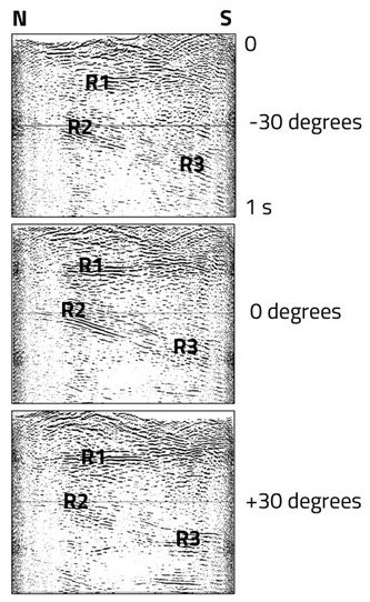
Figure 6Cross-dip analysis for Profile 3. The data have been stacked assuming different cross-dip angles of the reflections, i.e. dip perpendicular to the profile direction, which is approximately north-south. The cross-dip is measured relative to horizontal and defined as positive for reflections dipping to the east. Reflection R2 has the highest amplitude for zero cross-dip, whereas R1 and R3 has highest amplitude for 30° cross-dip towards east.
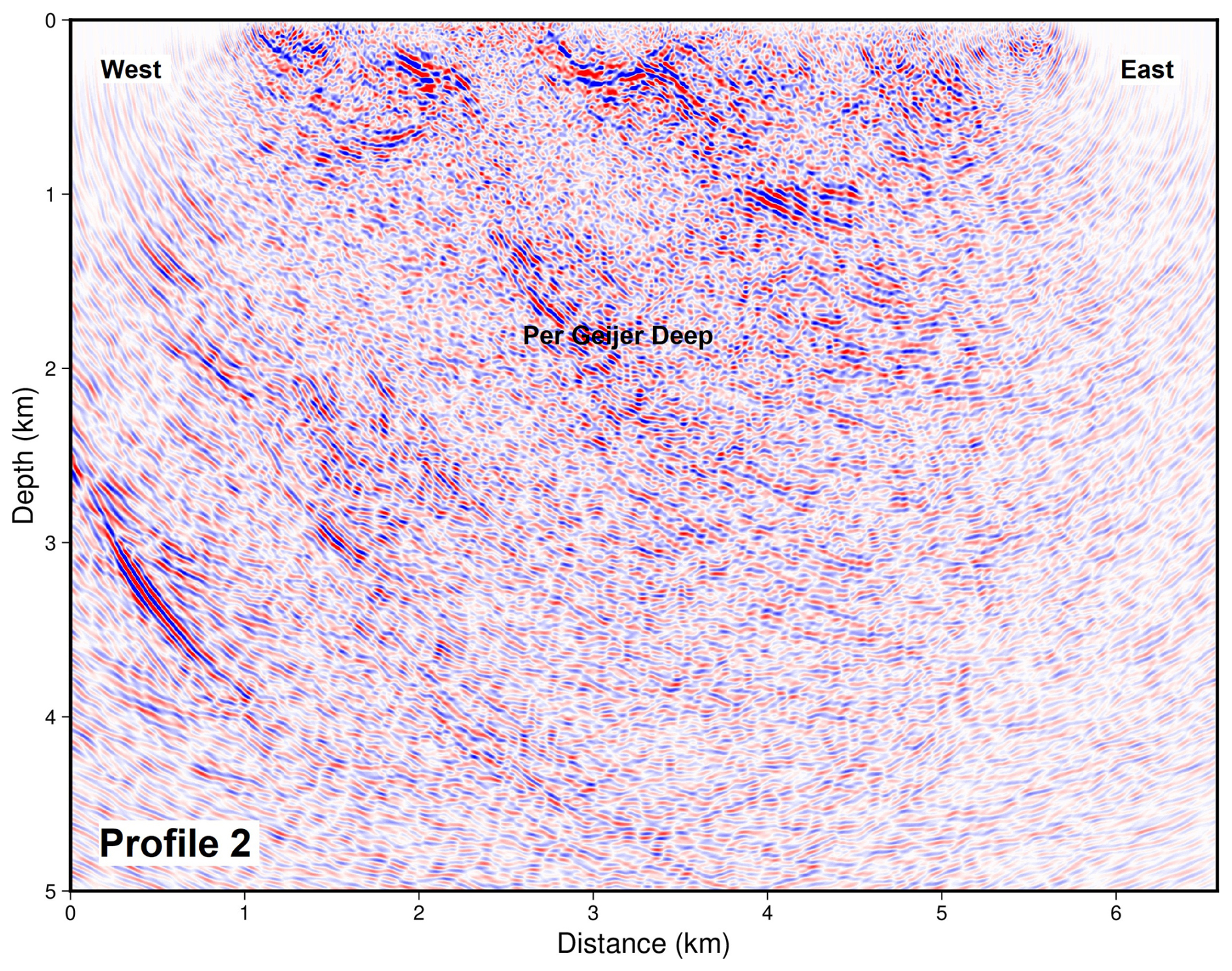
Figure 7Depth section from Profile 2, post-stack migrated. The profile has been padded by 1 km at both ends.
The 3D survey should be able to handle reflections with different dip directions in a better manner than the 2D profiles. However, the difficulty of simultaneously stacking moderately and steeply dipping reflections remains, when using CDP stacking followed by post-stack migration. The steeply dipping reflections will also cause reflection point dispersal or smearing. Pre-stack migration has therefore been used to handle variations in the dip of the reflectors. The velocity variations in the area are considered moderate, and therefore pre-stack time migration was judged to give sufficient accuracy. An example of a pre-stack migrated depth section is shown in Fig. 8 (see Fig. 2 for location). A steeply east-dipping reflection is observed, at the location of the main survey target, the Per Geijer Deep mineralization.
Further to this, a second approach have been used for the 3D processing, based on post-stack migration and lower frequencies, results of which are shown later in the paper. In this case, we chose moderately high NMO velocities, as a compromise to preserve also more gently dipping reflections.
All surface seismic data have been depth-converted using a constant velocity of 6000 m s−1.
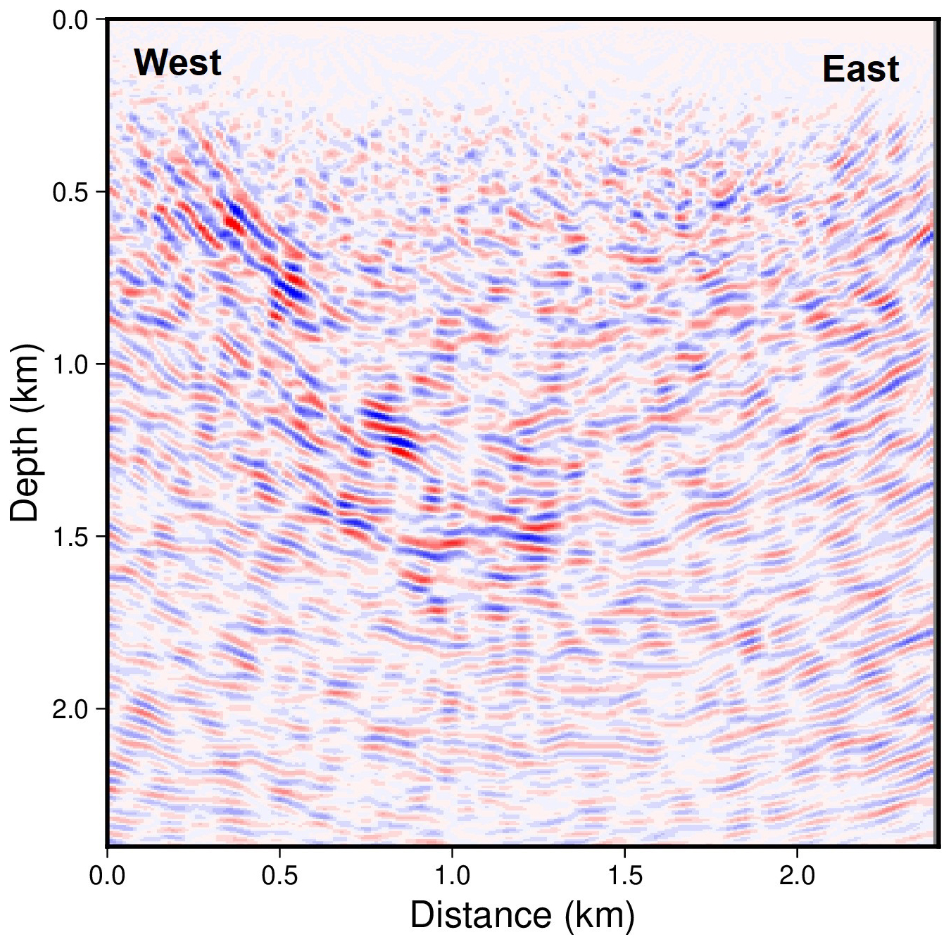
Figure 8Example inline section from pre-stack time migrated 3D data (see location in Fig. 2, right side). The section has been depth-converted.
4.3 Downhole seismic data processing and migration
Example walkaway VSP data from the northern hole are shown in Fig. 9. This hole is approximately 1700 m deep, as measured along the hole (not true vertical depth). The down-going P wave is generally seen along the entire hole. The uniaxial response of the fiberoptic cable could explain the apparent decrease of the P wave amplitude along some intervals of the hole, when the P wave arrives at an oblique angle relative to the hole axis. The record in Fig. 9B also show signs of down-going S-wave energy.
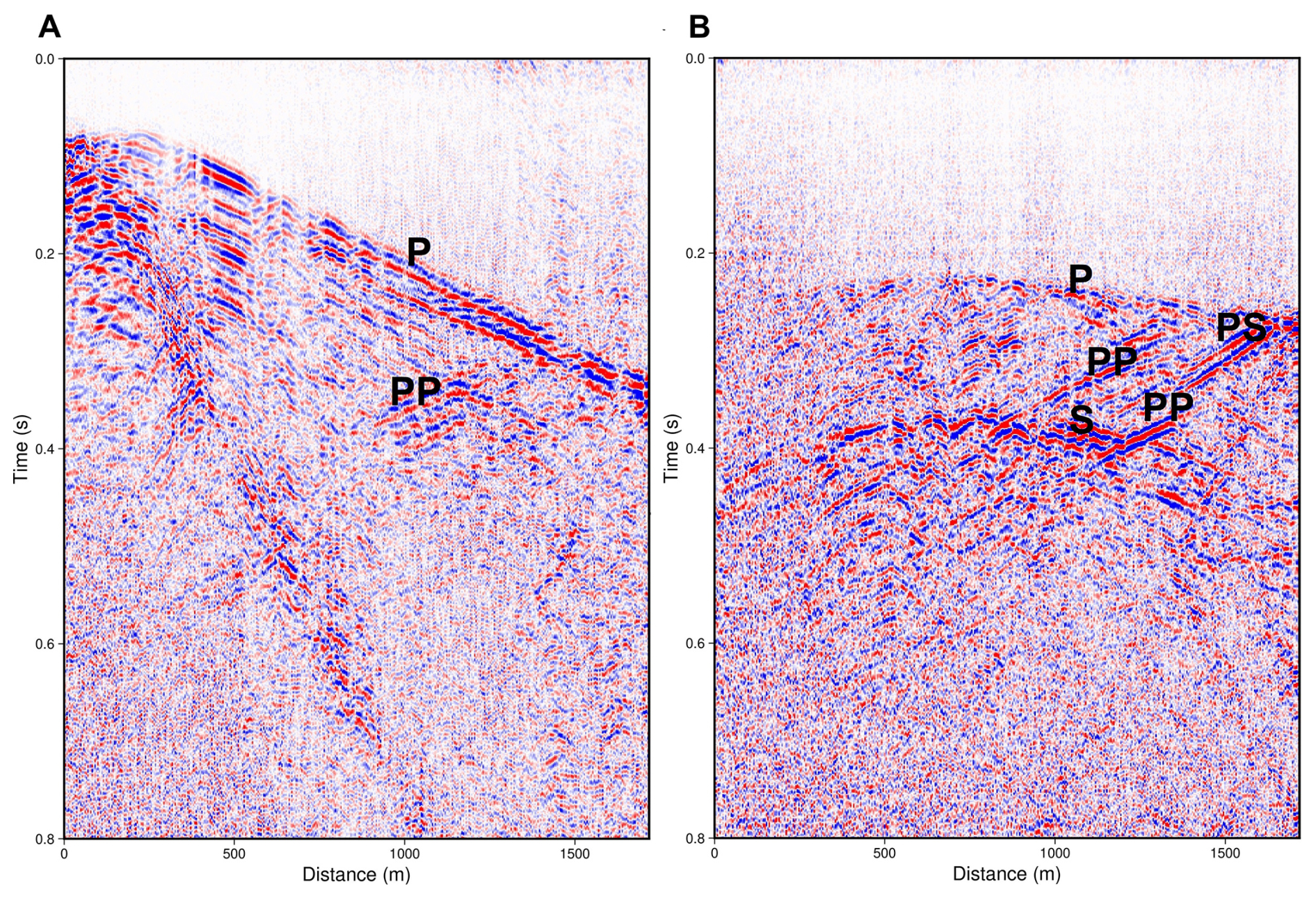
Figure 9Seismic records from the walkaway VSP survey, with increasing depth towards right (the x-axis shows distance as measured along the drill hole). (A) Record for a source point close to the drill hole. In this case the down going P-wave has a roughly linear appearance. (B) Record for a source at some distance from the drill hole, in which the down going P-wave shows curvature. For clarity, the tube waves have been suppressed prior to display. Spectral balancing and AGC have also been applied. See text for description of the annotated seismic phases.
Upgoing waves interpreted to be P-wave reflections (PP) can also be observed, originating from about 1500 m depth along the drill hole. For comparison, the geological logging shows that iron mineralization is mainly occurring within the intervals 1450–1550 and 1650–1700 m. There are signs of P-S converted reflections in some records, more clearly seen for source points at some distance from the drill hole (Fig. 9B).
To enhance the reflected waves prior to migration, median filtering was used to suppress the down going P and S waves, and the strong tube waves. Source statics from the simultaneous small surface 3D survey (not discussed further in this paper) were also applied to the VSP downhole seismic data.
For the migration, a basic migration code able to handle the downhole geometry was implemented. It assumes constant velocities and projects the amplitude for each data point onto an ellipsoid in the 3D volume surrounding the drill holes and the source point, taking the proper recording geometry into account. These ellipsoids are then summed to produce the migrated image. No amplitude corrections are included in the summation process, and the uniaxial response of the fiberoptic cable is not accounted for. A selection of Vibroseis source points within a radius of approximately 1 km from the drill hole collar were included in the migration, those further away were not used. The resulting migrated image shows a prominent reflection in good agreement with the model of the iron mineralization (Fig. 10). After some trials, a velocity of 5000 m s−1 was chosen for the migration, and for the inherent depth conversion. This is lower than the velocity used for depth-converting the surface seismic data, and the reason could be the quartzite units with relatively low velocity (cf. Fig. 3) which are dominant in this part of the survey area.
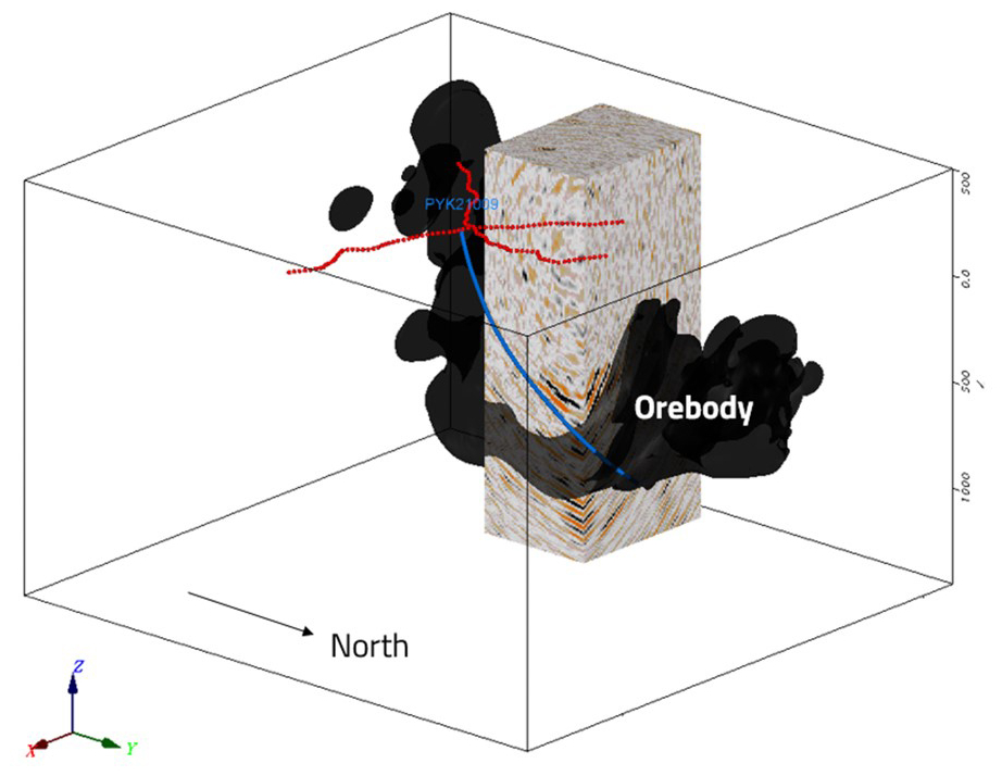
Figure 10Migrated depth volume from the walkaway VSP survey. The drill hole is shown in blue, and the red dots represent the source positions used for the migration.
The Kiirunavaara and Per Geijer iron-oxide deposits are well-constrained by drilling, and there are recently updated geological models for comparing with the seismic results. Various non-seismic geophysical surveys have also been conducted in the area, including geophysical wireline logging in many holes.
A comparison between the pre-stack migrated 3D seismic image and the deposit model for Per Geijer Deep shows a clear correlation between the most distinct reflections and the iron-oxide volume (Fig. 11). This is observed in all the seismic data from the Per Geijer area, and particularly evident in the migrated image from the walkaway-VSP survey (Fig. 10). Although it is often difficult to tie the reflections directly to the contacts of the iron mineralization, it seems likely that these iron-oxide deposits are causing much of the associated seismic reflectivity.
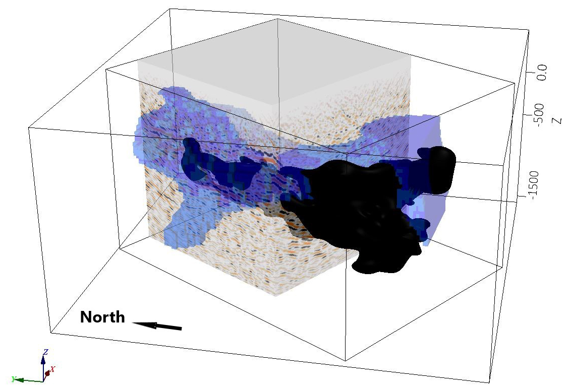
Figure 11Pre-stack migrated depth volume from the 3D survey, in comparison with the geological model for the Per Geijer Deep mineralization, shown in black. Also shown in blue is the electrical conductivity model from a semi-airborne EM survey (Smirnova et al., 2020). All cells with conductivity >0.02 S m−1 are shown. The seismic volume and the conductivity model are semi-transparent.
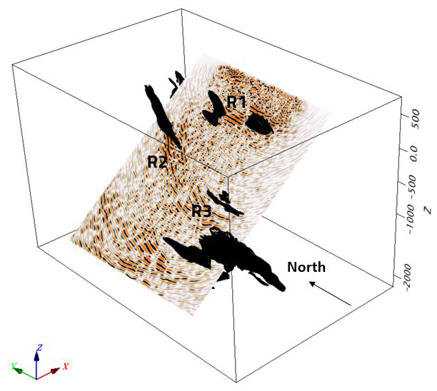
Figure 12Depth section from Profile 3, plotted at an angle to account for the reflections mostly coming from the western side of the seismic line. The geological models for the iron-oxides are shown in black.
Profiles 1 and 3 are oriented roughly parallel to the strike of the mineralization and most lithological contacts in the area, and therefore it would not be likely to see a correlation between the seismic reflections and the geological models if the seismic sections were plotted vertically. Instead, we compare the seismic sections with the geological models after tilting the sections at an angle of 30° from vertical towards west, in the expected direction of the incoming reflections. An example of this approach is shown in Fig. 12, for Profile 3. There is a clear correlation between the reflections and the occurrence of iron-oxides.
Although the 3D survey was designed to image the Per Geijer Deep mineralization, reflections are also observed from the northern end of the nearby Kiirunavaara iron-ore. This is clearly seen in the 3D seismic image from the post-stack migration processing sequence (Fig. 13B). An earlier seismic profile in the area also showed a reflection interpreted to originate from the Kiirunavaara ore (Jensen et al., 2012).
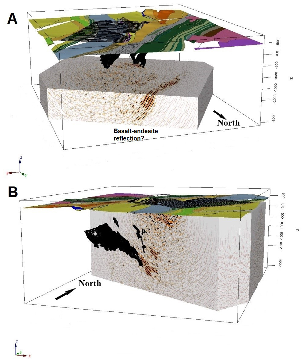
Figure 13Post-stack migrated depth volume, shown in two different views (A, B). The geological models are shown for comparison. The large geological unit visible in panel B is the northern end of the Kiirunavaara ore. Note that in image A the upper boundary of the seismic cube is at elevation −1700 m. The geological map from Fig. 1 has been draped on the surface, and the 3D receivers are also shown.
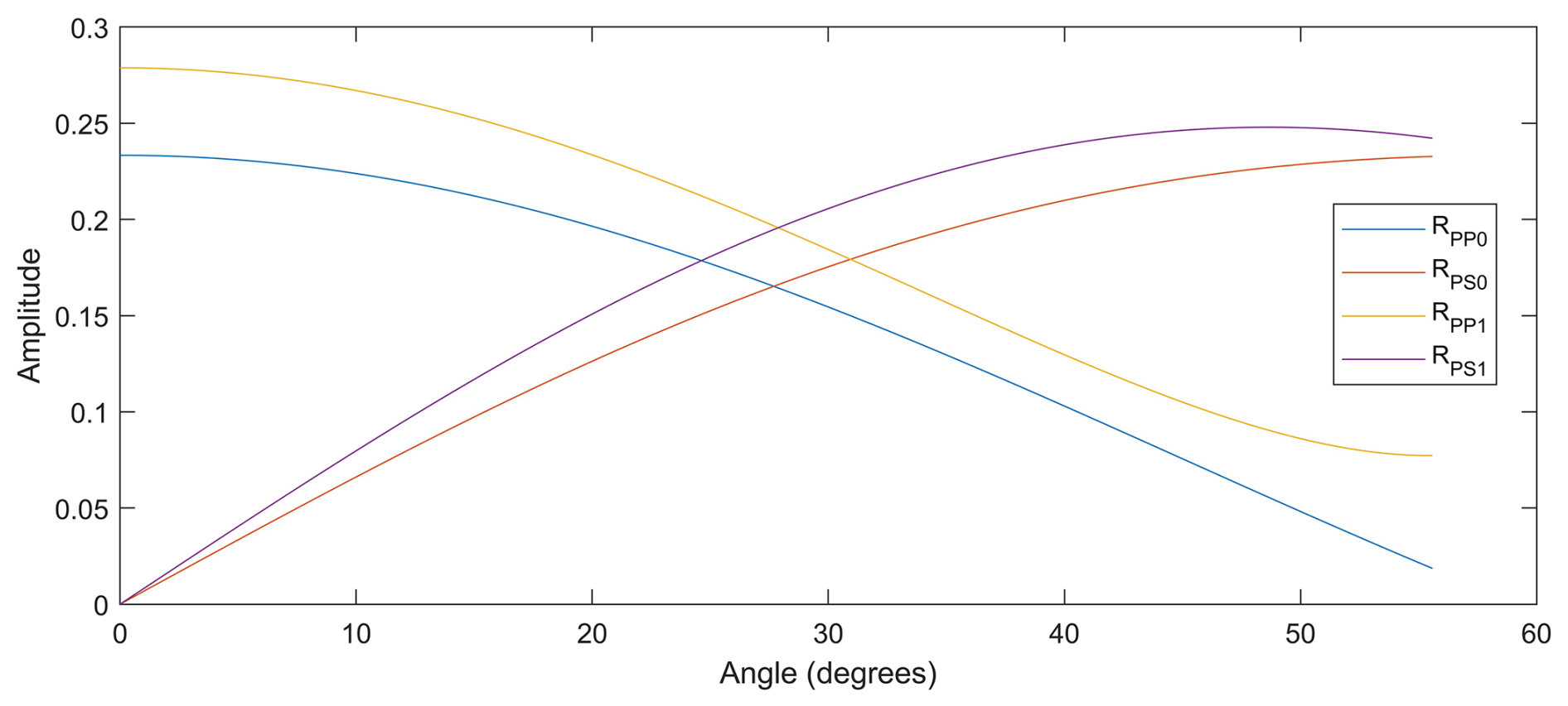
Figure 14Calculated approximate reflection coefficients for the Per Geijer Deep mineralization. The angle is measured relative to vertical, with 0° referring to normal incidence. RPP0 and RPS0 represent the case of no velocity contrast, whereas RPP1 and RPS1 represent a P-wave velocity increase from 5.5 to 6.0 km s−1, and S-wave velocities defined through a ratio of 1.72. For both cases, the density increases from 3.0 to 4.4 g cm−3 at the contact.
The sonic log in Fig. 3 only shows a slight increase in the P wave velocity for the Per Geijer Deep mineralization, relative to the host rock. Therefore, velocity variations do not appear to be the main cause of the observed reflections. However, the density contrast between the iron-oxides and the host rock is significant. To quantify the reflectivity of the iron-oxides, reflection coefficients for P-P and P-SV reflections have been calculated. The approximate equations which assume small contrasts in elastic properties were considered sufficient for this case (see p. 256 in Kennett, 2001). Based on the logs in Fig. 3, a P-wave velocity increase from 5.5 to 6.0 km s−1 and a density increase from 3.0 to 4.4 g cm−3 were judged to be a reasonably accurate representation of the boundary between the mineralization and the host rock. Lacking better information, the S-wave velocities were assumed to follow the P-wave velocities via the normally assumed ratio of 1.72 between these two. The calculated P-P reflection coefficient is approximately 0.28 at vertical incidence, decreasing to about 0.08 at an incidence of 55° (Fig. 14). At larger incidence angles the approximate equations fail, and such angles should in any case be uncommon for our survey geometries. The reflection coefficient only decreases slightly if no velocity contrasts are assumed, and the amplitude trend with respect to the incidence angle does not change significantly, except for very large incidence angles (Fig. 14). It should though be noted that the Matojärvi formation close to the PG Deep mineralization also can contain relatively dense mafic lithologies (Fig. 3), potentially generating reflections.
Of relevance for the walkaway VSP survey, the P-SV reflection coefficients were also calculated (Fig. 14), using the same parameters as for the P-P reflection calculations. The P-SV reflection shows zero amplitude at normal incidence, and an increase in amplitude with incidence angle. This agrees with the observation of P-SV appearing more clearly for source points further away from the drill hole (Fig. 9B).
The Luossajärvi mineralization (see Figs. 1 and 2 for location) does not have a clear expression in the 3D seismic data. The reflection R2 in the tilted depth section from Profile 3 (Fig. 12) correlates roughly with a postulated extension of this mineralization towards depth. However, this is not consistent with the cross-dip analysis, which indicated that this reflection originates underneath the profile and not to the west. A more refined analysis is probably required to explain the cause of the R2 reflection.
Another example in which the seismic data suggest an extension of the mineralization models is seen for Profile 2, where the migrated section shows the reflection interpreted to originate from Per Geijer Deep as extending to depths of about 2 km, which is deeper than reached by any drill holes in this area (Fig. 7). Although this is on the limit of the depth penetration for the survey, considering the steep dip of the mineralization.
An obvious question from an exploration perspective is whether there are signs of unknown mineralization in areas not covered by the drilling. Discussing this in detail is not the scope of this paper. There is however a reflection within the distance interval 4.0–4.5 km along Profile 2 (Fig. 7), which roughly coincides with a deep EM conductor observed in the semi-airborne EM survey from the DESMEX project (Smirnova et al., 2020). As observed in Fig. 12 the Per Geijer iron mineralization generates an EM response, indicating that a combination of seismics and EM could be a way to explore for iron mineralization. This reflection also coincides with greenstones present in this area (Fig. 1), which on their own are not exploration targets. Whether these greenstones could be the cause of the EM anomaly is not clear.
There are also at least two reflections to the west of the actual survey area, beyond the reach of any drill holes (Fig. 13A). The most pronounced one is clearly seen in Profile 2 (Fig. 7), and it was a dominating feature in the small 3D survey mentioned earlier. A possible explanation could be the 2.40–1.96 Ga basalt-andesite units to the west of the survey area, judging by where the reflection projects to the surface. Ground and airborne EM measurements show a pronounced electrical conductor roughly correlating with the basalt-andesite units (Smirnova et al., 2020), possibly partly caused by graphite. Sparsely located dynamite shots during an earlier reflection seismic profile in this area also indicated a pronounced east-dipping reflection, possibly extending to depths of 10 km or more (Juhojuntti et al., 2014).
The eastern part of Profile 2 crosses the regional Kiruna-Naimakka deformation zone (Bergman et al., 2001; Grigull et al., 2018, and references therein). However, it is difficult to see any obvious expression of this deformation zone in the seismic data, possibly due to the steep dip. Comparisons have also been made between the seismics and the deformation zone mapping carried out in connection with the exploration drilling, discussing this matter is however beyond the scope of this paper.
Surface and downhole seismic reflection measurements have been carried out at the Per Geijer field, close to Kiruna. Distinct reflections are observed from the main target, the Per Geijer Deep iron-oxide mineralization, and from the nearby Kiirunavaara iron ore. The steep dips of most structures in the area, including the contacts of the iron-oxides, pose a challenge for seismic imaging, both with respect to processing and data acquisition. Some of the seismic profiles were oriented almost parallel to the dominating strike direction in the area, which complicates the interpretation, although cross-dip analysis can be used to distinguish reflections coming from the side of the profiles. Downhole sonic and density logging indicates that the seismic response from the PG Deep mineralization is primarily due to the distinct density contrasts. Pronounced reflections are also recorded from the footwall of the mineralization, possibly caused by mafic units.
None of the computer codes used for the study are available.
The data used for the study are not available.
Łukasz Sito participated in planning the seismic surveys, organized much of the fieldwork, and prepared the Vibroseis data for further processing. Niklas Juhojuntti has carried out the further data processing and analysis, interpreted the data, and prepared the manuscript.
The contact author has declared that neither of the authors has any competing interests.
Publisher’s note: Copernicus Publications remains neutral with regard to jurisdictional claims made in the text, published maps, institutional affiliations, or any other geographical representation in this paper. While Copernicus Publications makes every effort to include appropriate place names, the final responsibility lies with the authors. Views expressed in the text are those of the authors and do not necessarily reflect the views of the publisher.
This article is part of the special issue ”Seismic imaging from the lithosphere to the near surface”. It is a result of the Seismix 2024 conference, Uppsala, Sweden, 24 to 28 June 2024.
The company OptaSense deployed and operated the fiberoptic cable used for the VSP surveys, and GeoVista (Sweden) conducted the density logging. Laura Lauri from LKAB contributed to the geological description. Globe Claritas™ was used for the seismic data processing, except for the VSP migration which was coded in Matlab™. The Generic Mapping Tool (GMT) package and OasisMontaj™ were used to create most of the illustrations. The field crews of Geopartner and LKAB are acknowledged for their work during the seismic surveys.
Comments by two reviewers improved the clarity of the paper.
This paper was edited by Michal Malinowski and reviewed by two anonymous referees.
Bergman, S., Kübler, L., and Martinsson, O.: Description of regional geological and geophysical maps of northern Norrbotten County (east of the Caledonian orogen), Sveriges geologiska undersökning Ba 56, ISBN 91-7158-643-1, 2001.
Cary, P. W. and Lorentz, G. A.: Four-component surface-consistent deconvolution, Geophysics 58, 383–392, 1993.
Donoso, G. A., Malehmir, A., Carvalho, J., and Araujo, V.: 3D reflection seismic imaging of volcanogenic massive sulphides at Neves-Corvo, Portugal, Geophysical Prospecting 71, 1116–1131, 2023.
Forsell, P.: The stratigraphy of the Precambrian rocks of the Kiruna district, northern Sweden, Sveriges Geologiska Undersökning C 812, Uppsala, ISBN 91-7158-354-8, 1987.
Geijer, P.: Igneous rocks and iron ores of Kiirunavaara, Luossavaara and Tuolluvaara, Scientific and practical researches in Lapland arranged by Luossavaara–Kiirunavaara Aktiebolag, Stockholm, 278 pp., https://doi.org/10.2113/gsecongeo.5.8.699, 1910.
Geijer, P.: Recent developments at Kiruna, Sveriges Geologiska Undersökning C 288, Stockholm, https://resource.sgu.se/dokument/publikation/c/c288rapport/c288-rapport.pdf (last access: 2 January 2026), 1919.
Grigull, S., Berggren, R., Jönberger, J., Jönsson, C., Hellström, F. A., and Luth, S.: Folding observed in Palaeoproterozoic supracrustal rocks in northern Sweden, in: Geology of the Northern Norrbotten ore province, northern Sweden, edited by: Bergman, S., Rapporter och Meddelanden 141, ISBN 978-91-7403-393-9, 2018.
Hloušek, F., Malinowski, M., Bräunig, L., Buske, S., Malehmir, A., Markovic, M., Sito, L., Marsden, P., and Bäckström, E.: Three-dimensional reflection seismic imaging of the iron oxide deposits in the Ludvika mining area, Sweden, using Fresnel volume migration, Solid Earth, 13, 917–934, https://doi.org/10.5194/se-13-917-2022, 2022.
Hloušek, F., Jusri, T., Buske, S., Heinonen, S., Karinen, T., Kozlovskaya, E., and Leveäniemi, H.: Seismic imaging of the crustal structure in the Sodankylä region (Finland): unveiling the Central Lapland Greenstone Belt's mineral potential, Geophys. J. Int. 241, 338–353, 2025.
Jensen, M.-B., Kashubin, A., Juhlin, C., and Elming, S-Å.: Multidisciplinary study of the hanging wall of the Kiirunavaara iron ore deposit, northern Sweden, Geophysics 77, B269–B285, 2012.
Juhojuntti, N., Olsson, S., Bergman, S., and Antal Lundin, I.: Reflexionsseismiska mätningar vid Kiruna – preliminär tolkning, SGU Report 2014:05, https://resource.sgu.se/dokument/publikation/sgurapport/sgurapport201405rapport/s1405-rapport.pdf (last access: 2 January 2026), 2014 (in Swedish).
Juhojuntti, N., Wood, G., Juhlin, C., O'Dowd, C., Dueck, P., and Cosma, C.: 3D seismic survey at the Millennium uranium deposit, Saskatchewan, Canada: Mapping depth to basement and imaging post-Athabasca structure near the orebody, Geophysics 77, WC245–WC258, 2012.
Kennett, B. L. N.: The Seismic Wavefield, Volume I: Introduction and Theoretical Development, Cambridge University Press, https://doi.org/10.1017/9781108780315, 2001.
LKAB: A summary technical report on the mineral resources of LKAB, Sweden – Per Geijer Iron oxide-Apatite deposit, https://lkab.mediaflowportal.com/documents/folder/231556/ (last access: 5 December 2025), 2024.
Malehmir, A. and Bellefleur, G.: 3D seismic reflection imaging of volcanic-hosted massive sulfide deposits: Insights from reprocessing Halfmile Lake data, New Brunswick, Canada, Geophysics 74, 209–219, 2009.
Malmgren, L., Saiang, D., Töyrä, J., and Bodare, A.: The excavation disturbed zone (EDZ) at Kiirunavaara mine, Sweden – by seismic measurements, Journal of Applied Geophysics 61, 1–15, 2007.
Martinsson, O. and Erlandsson, M.: Prospekteringsobjekt LKAB, ”Framtida järnmalmsfyndigheter i Malmfälten”, Fältarbete 2006–2008: objekt Lappmalmen, Geovista GVR 09018, p. 68, 2009.
Parák, T.: Kiruna iron ores are not “intrusive-magmatic ores of the Kiruna type, Econ. Geol., 70, 1242–1258, 1975.
Pertuz, T., Malehmir, A., Brodic, B., Ding, Y., De Kunder, R., and Marsden, P.: Broadband seismic source data acquisition and processing to delineate iron-oxide deposits in the Blötberget mine – central Sweden, Geophysical Prospecting, 70, 79–94, 2021.
Smirnova, M., Juhojuntti, N., Becken, M., Smirnov, M., and the Desmex, W. G.: Exploring Kiruna Iron Ore fields with large-scale, semi-airborne, controlled-source electromagnetics, First Break 38, https://doi.org/10.3997/1365-2397.fb2020070, 2020.
Wu, J., Milkereit, B., and Boerner, D. E: Seismic imaging of the enigmatic Sudbury Structure, Journal Geophysical Research, 100, https://doi.org/10.1029/94JB02647, 1995.
- Abstract
- Introduction
- The iron ores in the Kiruna area
- Physical rock properties
- Seismic surveys in the Per Geijer area
- Integration and interpretation
- Conclusions
- Appendix A
- Code availability
- Data availability
- Author contributions
- Competing interests
- Disclaimer
- Special issue statement
- Acknowledgements
- Review statement
- References