the Creative Commons Attribution 4.0 License.
the Creative Commons Attribution 4.0 License.
 | 05 Mar 2026
Where curling stones collide with rock mechanics: cyclical damage accumulation and fatigue in granitoids
Florian Fusseis
Ian B. Butler
Fatigue and damage accumulation in granitoids are classical, but poorly characterised, rock mechanics problems. We explore these phenomena by examining curling stone impacts. Curling stones are slid on ice and made to collide along a circumferential striking band. This well constrained scenario involves uniaxial compression of convex surfaces (i.e., Hertzian contacts). Conservatively, each stone experiences about 2900 impacts per season, over a lifespan of 10–15 years before refurbishment, providing a unique opportunity to study fatigue and damage accumulation under dynamic cyclic loading.
Here, we first determine the stress magnitudes of head-on curling stone impacts using on-ice experiments involving a high-speed camera and pressure-sensitive films. We then characterise the damage observed in aged stones using photogrammetry, microtomography, and microscopy. For high-velocity impacts (), a curling stone is locally and momentarily stressed to 300–680 MPa, exceeding its quasi-static unconfined compressive strength and exceeding the threshold for fatigue damage for repeated dynamic loadings. Curling stone impacts are dynamic in nature, as evidenced by (1) high strain rates () that lie below those of co-seismic rock pulverization; (2) ejection of rock powder during collisions and the presence of potential spalling microcracks; and (3) presence of striations on crescent-shaped fractures, which resemble mirror-mist-hackle patterns indicative of dynamic microcrack propagation. In the striking band, damage is confined to macroscopic Hertzian cone fractures and their immediate collet zones, and does not appear to extend beyond about 3–5 cm into the stones (radially). The circumferential density of cone fractures is limited to about 2–2.5 cm−1.
We propose that (1) early, high-velocity impacts initiate cone fractures up to a specific spatial density, and (2) with subsequent collisions in the same regions of the striking band, cone fractures progressively propagate and coarsen. This concentrates and channels the accumulated damage, shielding the rest of the stone from reaching critical stress levels for damage. Our findings are significant for applications where rocks are exposed to repetitive, high-stress impacts and suggest that narrow damage zones can dissipate high-impact stresses.
- Article
(21914 KB) - Full-text XML
- BibTeX
- EndNote


Mechanical impacts cause permanent damage when their associated stresses exceed a material's fracture strength. Where these impacts occur repeatedly, they lead to fatigue and an irreversible deterioration of a material's mechanical properties. Understanding the damage and fatigue of a material is an important condition for its use in engineering applications. Where these applications involve natural rocks, the characterisation of damage and fatigue becomes a rock mechanics problem. In fact, a great number of laboratory studies have addressed this problem for a wide range of natural rocks, often various types of building stones (e.g., Cartwright-Taylor et al., 2020; Moore and Lockner, 1995; Moore et al., 1987). In rock mechanics, understanding how a rock responds to mechanical loads and how its strength evolves through repeated loading is important for predicting the effects of rock falls and earthquakes, but also for evaluating their performance in structures such as tunnels and bridges. Here we opt for an unconventional approach to study damage and fatigue in rocks: we use the collision of curling stones to study damage evolution and fatigue in granitoids.
Curling is an Olympic winter sport in which athletes slide stones across a sheet of ice, aiming to eject the competitors' stones from a target area (Fig. 1a). Viewed from a geologist's perspective, the case of colliding curling stones poses a perfectly defined long-term rock mechanics experiment. Sample materials and dimensions are well known, with most curling stones coming from two locations in the UK and being machined to predefined standards (Leung and McDonald, 2022). During a game, the impact velocities and contact areas of colliding stones can be measured, and thus the impact stresses can be estimated. Curling stones are known to incur damage over their lifetimes, and eventually exhibit crescent-shaped fractures along their circumferential striking bands (Fig. 1b). After having been played for 10–15 years and having experienced a conservative 2900 collisions yr−1, every centimetre of a curling stone's striking band has experienced over 300 impacts. When curling stones are eventually retired, they allow for a detailed characterisation of the resulting effects on the rock macro- and microstructure. An experimental study of curling stone collisions offers an opportunity to quantify the impact process, and to explore how damage emerges and manifests itself in curling stones.
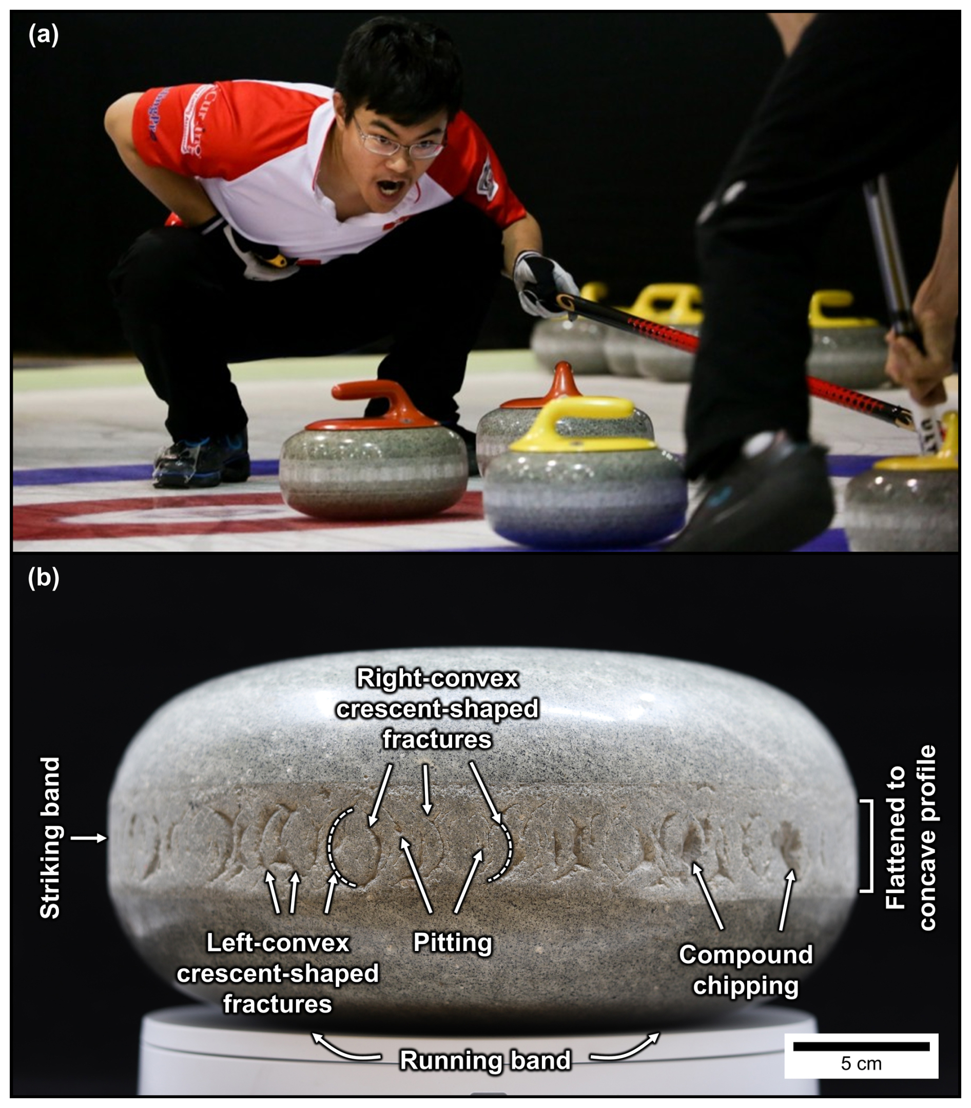
Figure 1(a) Curling stones collide with one another during a game (© 2017 World Curling Federation/Céline Stucki). (b) These collisions cause the accumulation of damage in the circumferential striking bands of curling stones, which manifests as crescent-shaped fractures, flattened to concave profiles, pitting, and compound chipping.
In this contribution, we seek to elucidate how damage accumulates in curling stones, and, by extension, more generally in granitoids. We combine on-ice collision experiments and detailed post-mortem analyses on retired stones to describe how curling stones from Ailsa Craig (Firth of Clyde, Scotland) are surprisingly effective in withstanding multiple high-impact events. Impact stresses of 300–680 MPa delivered with seismic strain rates are dissipated over macroscopic damage structures penetrating no deeper than 3–5 cm into the stones, even after many thousands of collisions. The resulting conceptual model for damage evolution in curling stones may be extrapolated to comparable scenarios in a geological or engineering context.
The stress of a curling stone impact can be estimated in two ways: (1) using an impact mechanics approach and (2) using a contact mechanics approach (Leung, 2020; Ling et al., 2018; Barber, 2018).
Following the impact mechanics approach, the average stress of the collision σavg can be calculated based on the average force Favg and collisional area A (Ling et al., 2018):
The average force, in turn, can be determined by Newton's second law:
where m=mass, p=momentum, Δt=contact time, and v′, v represent the final and initial velocities (respectively). The mass, velocity, and contact time can be measured from the on-ice experiments.
As an extension of the mechanical parameters, the average elastic strain εavg and strain rate can also be approximated, provided that the Young's modulus E of the material is known (Ling et al., 2018):
where ΔL is the change in the rock's length during deformation and L0 the undeformed length; and
It is important to note that the stress, strain, and strain-rate approximations introduced by the impact mechanics approach assume that elastic deformation occurs. However, the development of damage in curling stones indicates that some degree of inelastic deformation is present, meaning that the assumption of elastic deformation may oversimplify the calculations. However, given that most of the energy of curling stone impacts goes into the motion of the stationary stone (see Discussion), and that the damage occurs over hundreds to thousands of impacts (see Leung, 2025, https://doi.org/10.5194/egusphere-2025-3499-AC1 for calculations of the number of impacts a stone experiences over its lifetime), it is inferred that the majority of deformation occurs within the elastic region.
The contact mechanics approach assumes the static or quasi-static loading of two curved surfaces, modelled as prolate ellipsoids with combined curvatures κa and κb (i.e., Hertzian contacts). The contact area of these two ellipsoids generates a contact ellipse with semi-major and semi-minor axes a and b (where a>b). The mean stress σavg can be determined if the dimensions of the contact ellipse (a and b) and one of the two curvatures (κa or κb) are known (Barber, 2018):
where e is the eccentricity, and K(e), E(e) represent the complete elliptic integrals of the first and second kind, respectively, and E* is the composite Young's modulus which takes into account the Poisson ratio (ν) of the material:
As a note, curling stone impacts are inherently dynamic in nature. As such, stress is expected to propagate in waves, and the distribution of stress, strain, and strain rate is expected to be heterogeneous over space and time. Achieving stress equilibrium in simple, dynamic uniaxial experiments is already challenging (e.g., split-Hopkinson pressure bar experiments; Nemat-Nasser et al., 1991; Zhang and Zhao, 2014; Aben et al., 2017), and thus the style of damage produced by curling stones is expected to differ from dynamic uniaxial experiments due to the effects of heterogeneous stress, strain, and strain rate. The impact mechanics approach uses a time average and provides a first-order estimate of the stress, strain, and strain rate of curling stone impacts. On the other hand, the contact mechanics approach does not consider the dynamic nature of the experiments, but it does consider stress heterogeneities resulting from the geometry of the collisions. The complexity in determining the evolution of stress, strain, and strain rate cannot be fully documented in the on-ice experiments; as such, the reader is cautioned regarding the interpretation of the overly simplistic stress, strain, and strain-rate values determined in this contribution.
We studied curling stones from both Ailsa Craig (Firth of Clyde, Scotland) and Trefor (Llŷn Peninsula, North Wales). Two types of rocks from Ailsa Craig are used in curling stones: Ailsa Craig Common Green, which is currently used for the striking bands of Olympic-standard curling stones; and Ailsa Craig Blue Hone, which was used as the striking bands in older stones, but is currently inserted into the running bands of the stones (Leung and McDonald, 2022; see Fig. 1b for locations of the running band and striking band). Two types of rocks from Trefor are used in curling stones: Blue Trefor and Red Trefor, both of which are typically used for striking bands. In general, this study focuses on the rocks from Ailsa Craig, although we integrated several different rock types into the study: the on-ice experiments used Ailsa Craig Common Green; the macroscopic damage characterization predominantly used Ailsa Craig Blue Hone, with ancillary Ailsa Craig Common Green and Red Trefor samples; and the microfracture descriptions used only Ailsa Craig Blue Hone. The on-ice experiments were limited by the availability of actively used rocks at Curl Edinburgh. Different rock types were used in the macroscopic damage characterization to illustrate the full extent of damage in curling stones. Lastly, Ailsa Craig Blue Hone displayed the most developed crescent-shaped fractures and was thus the focus for the microstructural aspects of the study.
3.1 On-ice experiments
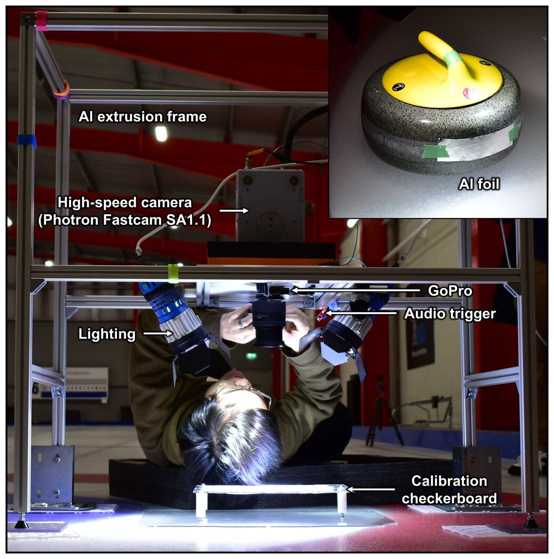
A series of n=30 on-ice experiments was devised at Curl Edinburgh (Edinburgh, UK) in order to determine the mechanical parameters of curling stone impacts. These 30 experiments consisted of (a) experiments using Fujifilm Prescale HHS pressure-sensitive films (n=4); (b) preliminary tests of aluminium foils without velocity analysis (n=4); (c) aluminium foil tests with velocity analysis (n=9); and (d) high-speed camera experiments (n=13). Of these thirty experiments, we report nine experiments that involve independent head-on collisions between a stationary stone and a moving stone that were delivered full-length by the 2025 World Men's curling champion and 2026 Olympic silver medallist Bruce Mouat (for an extended discussion of the discarded experiments, see Leung, 2025, https://doi.org/10.5194/egusphere-2025-3499-AC1). These Olympic-standard stones were composed of Ailsa Craig Common Green striking bands inserted with Ailsa Craig Blue Hone running bands, and were in new condition, having been used for less than one season. The velocity of the moving stone was systematically varied between the experiments. All experiments used a stopwatch to link impact velocities to the hog-to-hog reference times typically used in curling. Regular videography was tested and implemented into the experiments in order to track the initial and final velocities of the stones. Some experiments used pressure-sensitive films and aluminium foil to measure the contact area (Fig. 2), whereas others used high-speed videography to determine the contact time.
In curling, the velocities of curling stones are compared using stopwatches by recording the travel times of curling stones over distances marked by lines. The hog-to-hog time is a common frame of reference; this time interval is measured between the two hog lines that separate the two playing ends by a distance of 21.945 m (World Curling Federation, 2018). The typical hog-to-hog times for takeouts range between 6.5–12 s; thus, this range of velocities was used in the experiments. The 6.5 s dataset is referred to as the maximum velocity scenario, although greater velocities are achievable in practice.
Two GoPro Hero 4 cameras recorded the kinematic (i.e., position and velocity) data of curling stones at 240 fps, using WVGA resolution (800×400 pixels). These cameras were positioned on an aluminium frame above the stationary stone ∼0.5 m from the ice surface. The data were processed as a series of image frames, and were corrected for fish-eye lens distortion using the Camera Calibrator App in Matlab® with a series of oriented calibration checkerboard images. The undistorted frames were then transformed to orthographic frames (with real-world pixel dimensions) using a homography transform, with a calibration checkerboard as reference. The orthographic frames were analysed in Fiji (Schindelin et al., 2012, see File S1 in Leung et al., 2025, for the image processing workflow). The positions of curling stones were marked by visually fitting circles to the handles of the stones and recording the coordinates of the centres of the circles. The precision of the kinematic data was determined by comparing reprojections of the calibration checkerboard to actual checkerboard dimensions, along with comparing the measured dimensions of the handles and curling stones (see File S2 in Leung et al., 2025, for the error determination of positional kinematic data). No significant systematic error was produced by the correction of fish-eye lens distortion. To account for potential errors in the kinematic data, the 2σ values derived from this analysis were used for error propagation.
A high-speed camera (Photron Fastcam SA 1.1 Colour) was used to record the collisions and their respective contact times. The camera was equipped with a macro lens with no barrel distortion and recorded collisions at selected frame rates ranging between 10–40 kfps; the final dataset presented here was recorded at a frame rate of 40 kfps. The high-speed camera was triggered by external input, using a microphone sensor with an Arduino Uno interface. The data were processed as a series of still image frames, and a Sobel filter was applied in Fiji (Schindelin et al., 2012). The resulting images were used to determine when the stones were in collision.
Aluminium foil and pressure-sensitive film (Fujifilm HHS) were taped onto the striking bands of the stationary curling stone to determine the contact area and pressure distribution of the collisions. These films were subsequently scanned using a document scanner at 600 dpi, and the contact area and dimensions (i.e., width and height) were measured visually via Fiji (Schindelin et al., 2012).
Preliminary observation of the high-speed camera data showed evidence for the ejection of rock powder during curling stone collisions. We used a toothbrush to gently remove powdered material from the striking band of a currently used curling stone for analysis with a scanning electron microscope at the School of Geosciences at the University of Edinburgh.
3.2 Macroscopic damage characterization
The morphology of crescent-shaped fractures was documented using a combination of photography and 3D scanning of sections of aged striking bands from Leung (2019) and an additional, full Ailsa Craig Blue Hone stone (Fig. 1a). Although the macroscopic damage characterization focused on Ailsa Craig Blue Hone stones, we used ancillary Ailsa Craig Common Green and Red Trefor stones to illustrate the early stages of fracture development (no macroscopic crescent-shaped fractures were observed in Blue Trefor samples). The shape and size of crescent-shaped fractures were determined by digitising the outlines of crescent-shaped fractures from photographs using equally spaced points in Fiji (Schindelin et al., 2012). To determine the radius of curvature of the fractures, the points were fit to a circle using least-squares regression by minimising the error between observed and calculated radial distances. Other curved fits, including ellipses and superellipses, were tested; however, these fits were found to be unsuitable because the fractures are not closed curves. For partially developed crescent-shaped fractures, the y axis centre was fixed to the centre of the striking band in order to prevent mathematically non-sensible results. The least-squares fit thus models the fractures as circular arcs, which are each defined by a radius of curvature and central angle (here called the angular length).
The distribution of crescent-shaped fractures was determined from a full, aged Ailsa Craig Blue Hone curling stone. This curling stone was placed on a rotating table and was photographed in 34 sections, with each section representing ∼11°. These sections were then manually aligned to form a rolled out cylinder of the striking band. This resultant panoramic image was analysed using digital image analysis in the Fiji environment (Schindelin et al., 2012). To determine the density and distribution of crescent-shaped fractures, a horizontal transect line was drawn across the middle of the striking band, and the intersection of the crescent-shaped fractures with the horizontal transect line was recorded. Some incipient fractures did not directly intersect the transect line, although these commonly had visible components above and below the transect line. In these cases, the incipient crescent-shaped fractures were projected to intersect the transect line. The crescent-shaped fractures were classified by orientation (left- or right-convex) in order to evaluate any preferences in orientation.
The 3D morphology of crescent-shaped fractures was documented by (1) structured-light 3D scanning, (2) structure-from-motion photogrammetry, and (3) synchrotron-based X-ray microtomography (SµCT). Structured-light 3D scanning was conducted with an EINSCAN Pro 2X Plus in fixed scan mode (∼40 µm resolution). For structure-from-motion photogrammetry, photos of varying orientation were taken with a Samsung Galaxy Edge 7 and processed using Meshroom (AliceVision, 2018) to produce 3D models of the samples. To look at the distribution of large-scale damage structures and microfractures within the samples in 3D, one sample was scanned using SµCT at the Advanced Photon Source, beamline 2-BM (Micro-tomography) with a 30 keV pink beam. The scan consisted of 3600 projections (0.05° steps) with a 0.05 s exposure time, with a projection size of 3456×1202 pixels, and a pixel size of 3.13 µm. The projections were reconstructed using TomocuPy (Nikitin, 2023). Segmentation of fractures was conducted using the multi-scale Hessian fracture filter (Voorn et al., 2013).
3.3 Microscopic damage characterisation
In order to determine the microscale damage of curling stones, image mosaic transects measuring were collected from polished thin sections made from pristine Ailsa Craig Blue Hone samples (that were not manufactured into curling stones), as well as radial cuts through variably aged Ailsa Craig Blue Hone. Backscattered electron image mosaics (SEM-BSE) were acquired using a Carl Zeiss SIGMA HD VP Field Emission SEM under the following conditions: 2000× magnification, 15 kV accelerating voltage, 30 µm aperature size, and 6.9–7.1 mm working distance. The image mosaic transects were divided into 4 × 4 tiles and segmented for voids, quartz, albite, alkali feldspar, arfvedsonite, and high-field-strength-element (HFSE) minerals in Fiji (Schindelin et al., 2012) using the Trainable Weka Segmentation plugin (Arganda-Carreras et al., 2017). This segmentation yielded probability maps, which were segmented by binary thresholding at a probability of ≥0.5. Higher probability thresholds were attempted, but produced >10 % unassigned pixels in some tiles (see File S3 in Leung et al., 2025, for probability threshold analyses of selected tiles; a discussion on the choice of probability threshold can also be found in the open discussion of this paper: Leung (2025), https://doi.org/10.5194/egusphere-2025-3499-AC1). Initially, alkali feldspar and end-member albite were segmented separately; however, due to the variable composition of alkali feldspar, this resulted in a significant number of unassigned pixels. Thus, alkali feldspar and albite were not distinguished, and the sum of alkali feldspar and albite probability maps was used for image segmentation analysis.
The phase map for voids represents a combination of fractures and pores, so an attempt was made to distinguish fractures from pores. Generally, fractures have a larger perimeter-to-area ratio. Thus, the phase maps for voids were further subdivided based on circularity (c):
where A=area and P=perimeter of void. A threshold of c=0.1 was chosen by visual comparison; however, this subdivision could not distinguish between fractures and complex porosity (often associated with feldspar phenocrysts), and thus the c=0.0–0.1 subdivision reflects a combination of fractures and complex pores. The void (c=0.0–0.1) phase map was used to produce a damage profile for damaged and pristine samples in Fiji (Schindelin et al., 2012).
4.1 On-ice experiments
Of the 30 experiments we conducted in total, we report 9 experiments here (kinematic and contact-area data are reported in File S4 in Leung et al., 2025). The impact velocity was varied between 0.5–2.9 m s−1 to determine how contact area and stress vary with impact velocity (see the methods section for details of the on-ice experimental configuration).
Figure 3 shows a sequence of high speed camera frames depicting one of the collisions (Exp. 2.13), with the stationary stone visible at the bottom edge of the frames. For a radial impact velocity of the contact time was found to be frames (frames 331–354) at 40 kfps or . Frames 354 and 400, which capture the separation of the two stones, show that the collision also leads to the production and ejection of rock powder. An analysis of this rock powder using SEM-BSE (Fig. 4) and energy-dispersive X-ray spectroscopy showed that most of the particles are monomineralic, and revealed a distribution of fragment sizes with larger components formed by conchoidal drusy quartz and alkali feldspar phenocrysts, along with finer grains formed by minerals with a good cleavages (e.g., feldspars and amphiboles).
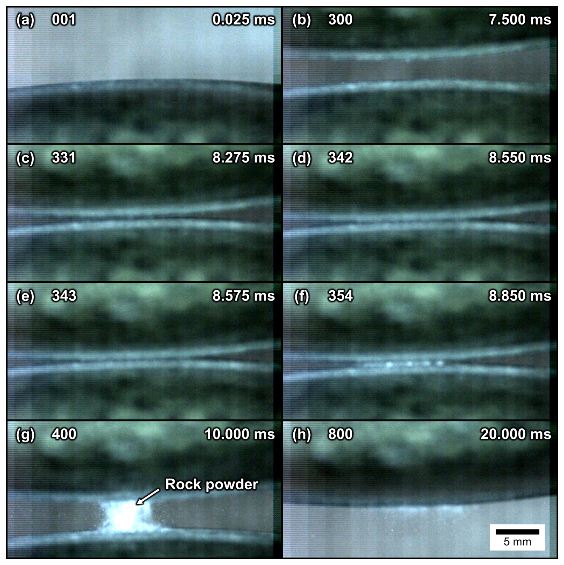
Figure 3Selected frames from high-speed camera experiment recording maximum-velocity scenario at 40 kfps using Ailsa Craig Common Green stones (Exp. 2.13). Key frames are shown at different intervals: (a) start of experiment, (b) pre-collision, (c) earliest estimate of collision start, (d–e) mid-point of collision, (f) latest estimate of collision end, (g) post-collision and (h) end of data collection (see Video S1 in Leung et al., 2025, for the unabridged video).
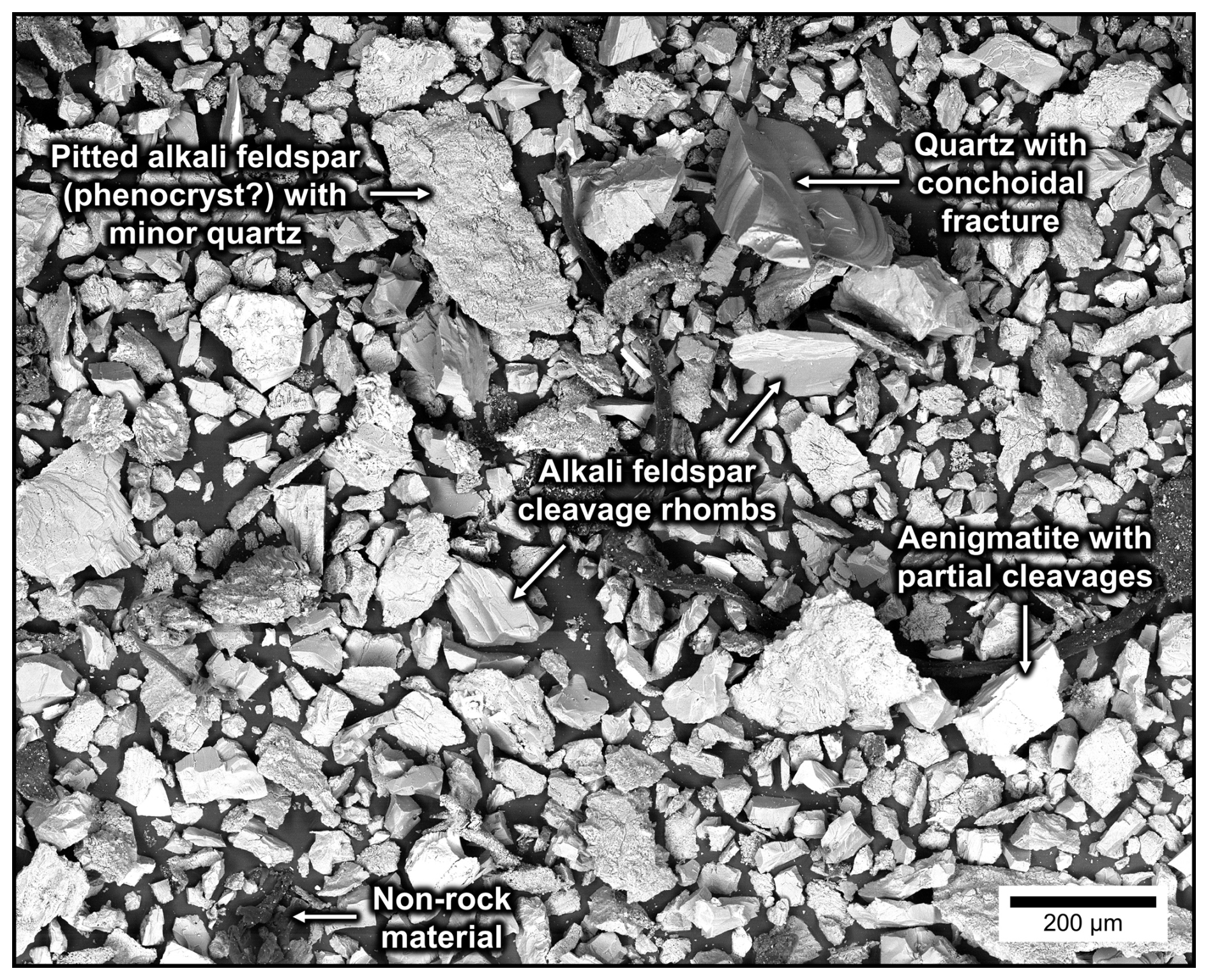
Figure 4Representative backscattered electron (SEM-BSE) image of the rock powder from the striking bands of Ailsa Craig Common Green curling stones from Curl Edinburgh (Edinburgh, UK).
The contact areas have superelliptical shapes that result from the geometry of the striking band and its vertical extent. They scale with the impact velocity, where higher velocities cause larger contact areas (Fig. 5a–g). The larger contact areas reflect greater deformation and thus are indicative of higher contact stresses. We used pressure-sensitive film (Fujifilm Prescale HHS) to measure the contact stress for one experiment (Fig. 5h). In this film, the degree of colour saturation indicates the pressure in static loading scenarios. The film we used was calibrated to 300 MPa and is fully saturated in our experiments, yielding a lower bound for the contact stress of 300 MPa. As a note, some caution must be advised on this estimation method, given that the pressure-sensitive films are calibrated for static loading conditions (as opposed to the dynamic loading conditions of curling stone impacts).
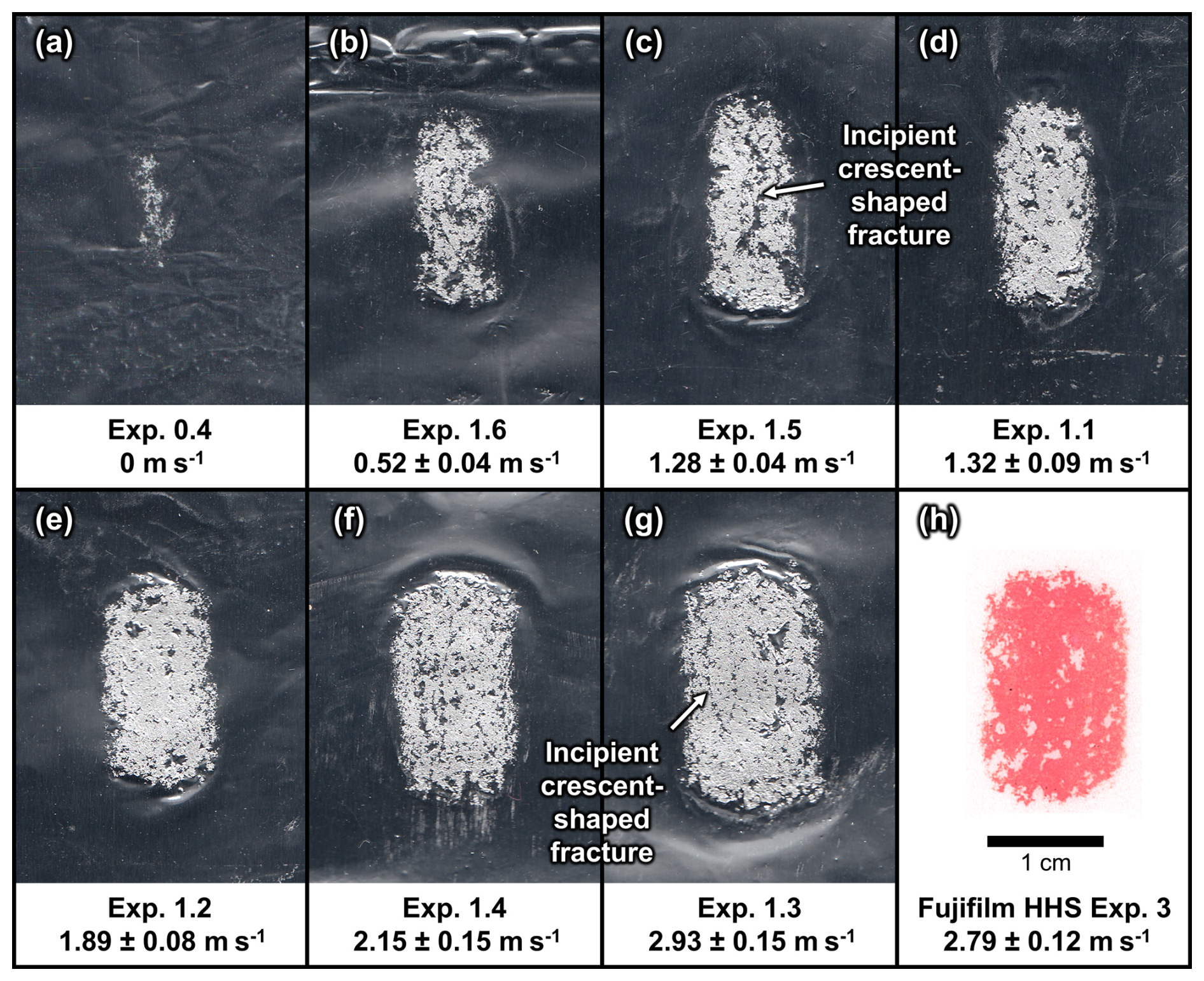
Figure 5Contact areas recorded from various on-ice experiments using Ailsa Craig Common Green striking bands at Curl Edinburgh (Edinburgh, UK). (a–g) Contact areas recorded on aluminium foil at increasing normal velocities: (a) 0 m s−1, (b) , (c) , (d) , (e) , (f) , (g) . (h) Contact recorded on Fujifilm HHS pressure-sensitive film (at ) shows fully saturated contacts, indicating stresses in excess of 300 MPa.
Using Eq. (5) of the contact mechanics approach, we can calculate the impact stresses. For the maximum impact velocity of , we determined an average stress over the contact area σavg of 680 MPa (with a minimum error on the order of ∼30 MPa based on the estimate of Poisson's ratio; Leung, 2020). Alternatively, using the impact mechanics approach (Eqs. 1 and 2), we arrive at an average stress over the duration of the collision of 550±80 MPa, which agrees with the former approach (see File S5 in Leung et al., 2025, for calculations). For the same impact velocity we also calculated the minimum elastic strain and strain rate using Eqs. (3) and (4), assuming for the sake of simplicity that all strain is accommodated elastically, and a Young's modulus value of 39 GPa for Ailsa Craig Common Green (Leung, 2020). This calculation yields a time-averaged elastic strain of 1.4±0.2 % and a time-averaged elastic strain rate of .
4.2 Macroscale damage characterisation
4.2.1 Morphology of crescent-shaped fractures
Aging curling stones made from Ailsa Craig are known to develop crescent-shaped fractures along their striking bands. These fractures also occur in stones from other localities (e.g., Trefor quarry, North Wales) but are less commonly observed. The stone shown in Fig. 1b has likely been played for several decades and exhibits a severely damaged circumferential striking band, typifying the macroscopic damage that curling stones incur over their lifetimes. Crescent-shaped fractures represent the dominant damage type along with flattening of the striking band. At first observation, crescent-shaped fractures are 2–3 cm long, curvilinear fractures that extend to some depth into the curling stone. Flattening of the striking band is visible over time, as the striking band profile is typically convex for new stones, but becomes progressively concave as the stones age. Concave striking bands commonly develop undesired chipping and widening of the striking band margins. The preferential pitting of phenocrysts, as well as compound chipping from intersecting crescent-shaped fractures, represent lesser damage features. Here, we focus mainly on characterizing the crescent-shaped fractures, which stand out due to their distinctive morphology.
Our macroscopic characterisation, which uses photogrammetry, structured-light 3D scanning (Fig. 6a–c) and SµCT imaging (Fig. 7d) combined with digital image analysis, reveals details on these fractures. Crescent-shaped fractures are convex in both trace and depth profiles, with a morphology approximating a paraboloid or conoid. The fracture surface shown in Fig. 6a–c has a pearly lustre and has striated corrugations which emanate from the striking band. This sample shows that crescent-shaped fractures can extend at least as deep as 1.5 cm from the striking band (in general penetrating to a maximum of 3–5 cm). A SµCT scan of a similar, but unexposed fracture (Fig. 7c) displays similar features, and, most interestingly, confirms that the damage is restricted to the crescent shaped-fracture and associated subsidiary damage in their collet zone, which is the wedge between the crescent shaped fracture and the striking band (Fig. 7c).
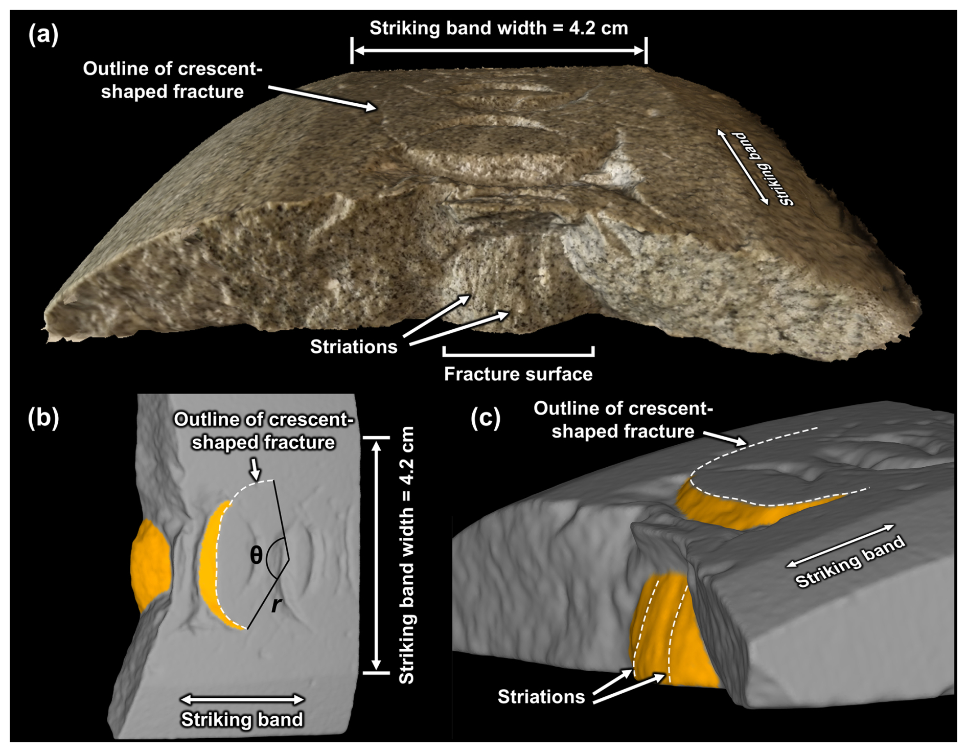
Figure 6(a) Photogrammetric and (b–c) structured-light 3D scans of an Ailsa Craig Blue Hone striking band (AC-01), in which the 3D morphology of an isolated, mature-stage crescent-shaped fracture is exposed (note that the majority of fractures in this sample are juvenile). (a) Oblique radial view of striking band (with color and topography); the surface of the crescent-shaped fracture has a pearly lustre and is striated. (b) Tangential view of striking band (topography only), showing the orientation of the crescent-shaped fracture (orange) with respect to the striking band; the statistical analyses for radius of curvature (r) and angular length (θ) are illustrated. (c) Oblique profile view (topography only) showing that the crescent-shaped fracture resembles a parabaloid, i.e., it is convex in three dimensions. The striations on the surface of the fracture emanate from the striking band.
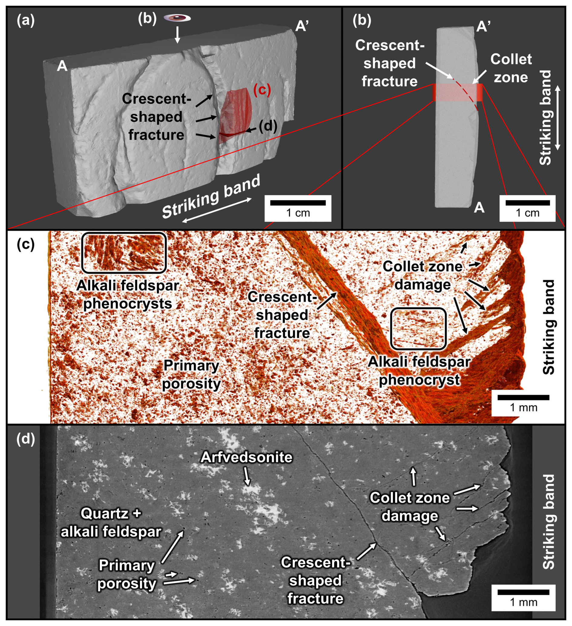
Figure 7Synchrotron-based microtomographic scan of an Ailsa Craig Blue Hone sample (thin-section cutoff) with juvenile to mature crescent-shaped fractures (AC-03-2). (a) 3D scan overview of sample, with locations for subfigures b–d. (b) Top view of sample, showing the viewing orientation for c. (c) Results from multi-scale Hessian fracture filtering (Voorn et al., 2013), showing fractures and void spaces; note in particular the orientation of the crescent-shaped fracture, damage in the collet zone, as well as porosity detected in alkali feldspar phenocrysts and in the groundmass. (d) Representative tomograph showing the differences in attenuation between various minerals with respect to fractures and porosity.
4.2.2 Macroscale evolution of the shape and distribution of crescent-shaped fractures
Crescent-shaped fractures are discrete, spaced fractures, which have two distinct orientations (left- or right-convex; Fig. 1b). None of the fractures appear to be closed forms (i.e., complete ellipses or circles). Crescent-shaped fractures range in their degree of development – both within individual samples and between different samples – from incipient (partially formed fractures, which may be formed in segments) and juvenile (fully linked crescent-shaped fractures, with 3D fracture surface hidden) to mature (fully linked crescent-shaped fractures, with 3D fracture surface exposed). Despite the typical crescent-shaped morphology of the fractures, irregular fractures also exist; these commonly represent incomplete, incipient fractures or compound chipping due to the intersection of two fractures. Moreover, the fractures may consist of multiple, superimposed crescent-shaped fractures that bifurcate towards the margins of the striking bands. These overprinting fractures are more common on mature striking bands (e.g., Fig. 8d).
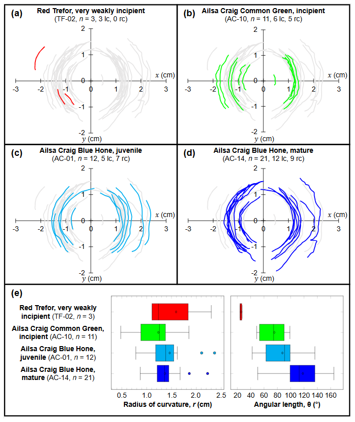
Figure 8Digitised crescent-shaped fractures of selected sections of striking bands, normalized to the centre of curvature, and presented in order of increasing damage state: (a) Red Trefor sample TF-02, (b) Ailsa Craig Common Green sample AC-10, (c) Ailsa Craig Blue Hone sample AC-01, and (d) Ailsa Craig Blue Hone sample AC-14. In each subfigure, the whole data set is shown in grey to contextualize relative distributions in morphology. Abbreviations: lc = left-convex, rc = right-convex crescent-shaped fractures, n = number of observed fractures in striking band segment. (e) Statistics of the digitised crescent-shaped fractures, with the radius of curvature (r, left graph) showing less variation with damage state, and the angular length of the fractures (θ, right graph) increasing with damage state (see Fig. 6 for an illustration of r and θ). Filled circles represent outliers.
The radius of curvature of the crescent-shaped fractures varies between 0.5–2.5 cm, and does not appear to be markedly different between samples of different damage state or rock type (Fig. 8e). The interquartile range of the radii of curvature (illustrated by the width of the boxes on Fig. 8e) decreases as the damage state increases; this may in part be related to the variation in the sample size between each curling stone sample, with a smaller sample size correlating with greater variation. On the other hand, the angular length of crescent-shaped fractures (Fig. 8e) increases as a function of age, suggesting that crescent-shaped fractures grow over repeated impacts.
The total density of crescent-shaped fractures does not increase significantly after the damage state exceeds an incipient state (Fig. 9), although it should be noted that pristine to weakly incipient stones (such as TF-02) have distinctly lower fracture densities. This suggests that the density of crescent-shaped fractures must increase between the weakly incipient and incipient damage states, at which point the striking band becomes saturated in crescent-shaped fractures.
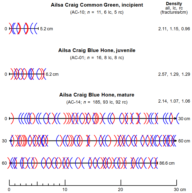
Figure 9Distribution of macroscopic crescent-shaped fractures from various aged striking band samples. Left-convex fractures are marked with blue opening parentheses, whereas right-convex fractures are marked with red closing parentheses. Sample TF-02 (Red Trefor, very weakly incipient) is not shown due to the lack of intersection data. Symbols and abbreviations: lc = left-convex, rc = right-convex, n = total number of observed fractures.
The number of left- and right-convex crescent-shaped fractures is approximately equal in the observed samples (Fig. 9), suggesting that both have equal probability of forming. However, it is evident that there are domains dominated by left- or right-convex crescent-shaped fractures. In other words, left- and right-convex fractures do not form conjugate sets.
As a note, our macroscale analysis of the morphology and distribution of crescent-shaped fractures in this section utilizes samples spanning several different rock types. Due to the lack of sample availability, it was not possible to compare the same rock type with different damage states. As such, we do not consider the effect that different mechanical properties may have on the development of crescent-shaped fractures.
4.3 Microfracture descriptions
4.3.1 Microscale anatomy of crescent-shaped fractures
In a radial view observed in thin section (Fig. 10a), crescent-shaped fractures in aged Ailsa Craig Blue Hone stones approximate circular arcs. However, at the ends of the fractures, they become horizontally asymptotic in attitude (Fig. 10b). This horizontal asymptotic rollover is not observed for the equatorial sections of the crescent-shaped fractures imaged in 3D (Fig. 6), suggesting that crescent-shaped fractures are not axially symmetric. Moreover, the crescent-shaped fracture shows minor undulations (Fig. 10a), which could represent a cross-sectional view of the striations reported in the macroscopic characterisation (Fig. 6). In the collet zone, which is located between the crescent-shaped fracture and the striking band, there is a narrow, localised damage zone, and towards the striking band, there are low-angle microcracks that may be produced by spalling (Fig. 10c). Behind the crescent-shaped fracture and towards the centre of the curling stone, the sample appears to be pristine. In the following section, we take a closer look at the microcracks found in this sample using segmentation analysis of SEM-BSE images (Fig. 11).
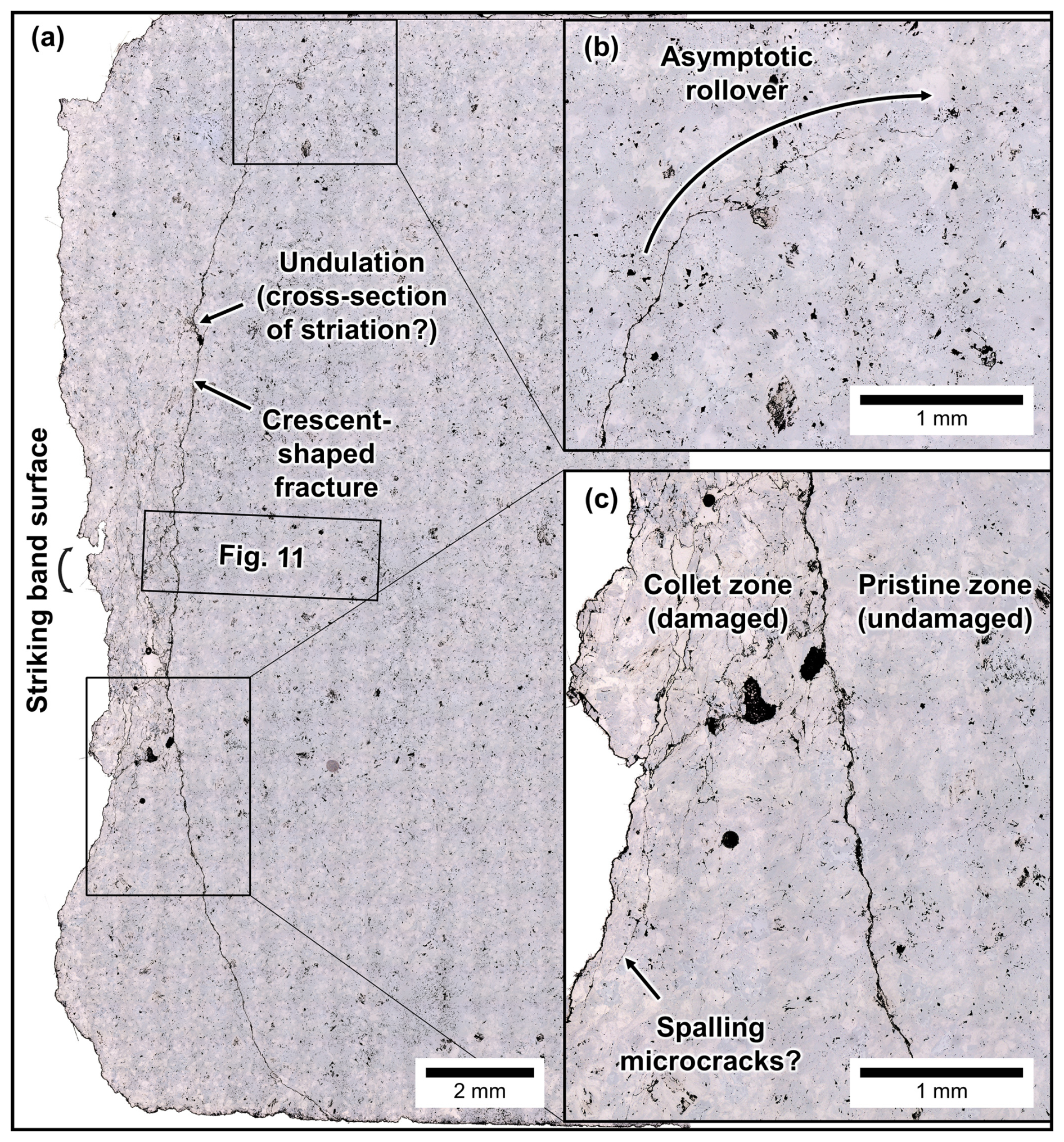
Figure 10(a) Radial section of Ailsa Craig Blue Hone striking band showing juvenile fractures under reflected light (sample AC-03-1). (b) Near the margins of the crescent-shaped fracture, the curvature of the crescent-shaped fracture rolls over to become horizontally asymptotic. (c) Damage is strongly restricted to the collet zone (the collet zone is a wedge-shaped area located between the crescent-shaped fracture and the striking band). Some microcracks are visible near the surface of the striking band and may correspond to spalling.
4.3.2 Damage profile analysis
Segmented phase distribution maps derived from digital image analysis of SEM-BSE maps (Fig. 11a) illustrate the microscale characteristics of the crescent-shaped fracture and associated damage zone (Fig. 11b). A profile of voids with circularity between 0–0.1, which reflects fractures and complex zones of porosity, yields an approximate damage profile (Fig. 11c–d). This profile shows that the damage increases from the striking band to the main fracture and sharply diminishes to a pristine state towards the centre of the stone. Between the striking band and the main crescent-shaped fracture, the percentage of pixels relating to segmented fracture porosity exceeds that of the pristine sample (AC-12, blue line, Fig. 11d). On the other hand, towards the interior of the stone, the pixel density generally falls below that of the pristine sample (Fig. 11). Outliers within the interior of the stone are related to zones of complex porosity within feldspar phenocrysts (Fig. 11b–c). In total, the damage profile shows that the damage is strongly restricted to crescent-shaped fractures and localised damage zones.
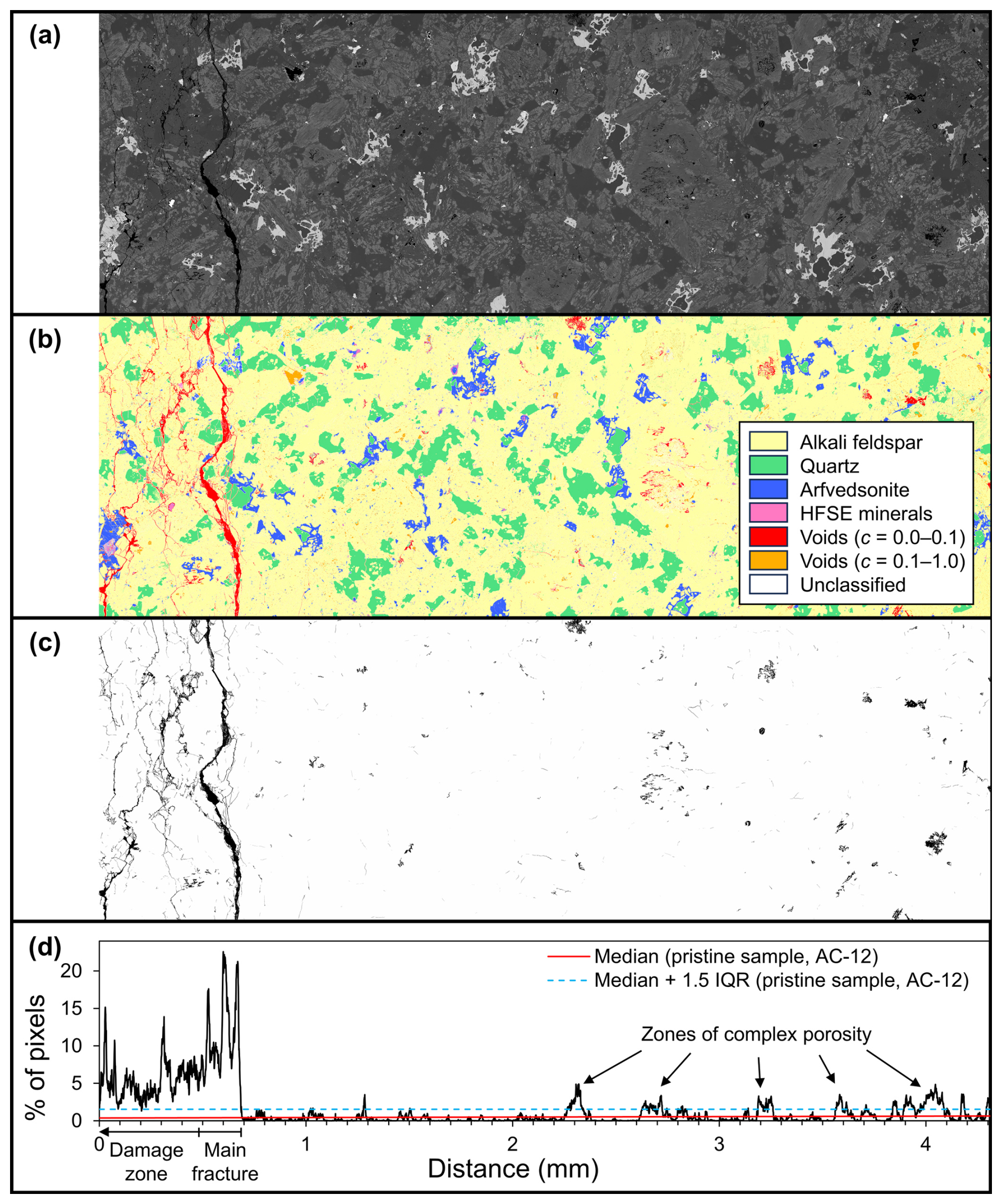
Figure 11Segmentation analysis of a SEM-BSE image for Ailsa Craig Blue Hone sample AC-03-1 (see location in Fig. 10). (a) Original SEM-BSE image. (b) Segmented map of various minerals and voids. (c) Segmented maps of voids with circularity between 0–0.1. (d) Percentage of pixels classified as voids with circularity between 0–0.1 along the horizontal transect of (b), which serves as a proxy for the damage profile. From left to right (going from the striking band towards the centre of the stone), the damage increases towards the crescent-shaped fracture and immediately reverts to pristine levels past the crescent-shaped fracture (see text for discussion).
Given that the damage is strongly restricted to crescent-shaped fractures and localised damage zones, the segmented map for AC-03-1 can be subdivided into damaged and pristine regions. Digital image analysis of the two regions shows a 5.3 % increase in voids with circularity between 0–0.1 and a 4.5 % increase in unclassified pixels for the damaged region, which correlates to an increase in microcracks. The ratio of alkali feldspar to quartz in the damaged region (6.4) is higher than that of the pristine region (4.9), suggesting that the abundance of quartz is lower in the damaged region. This could be due to (1) mineralogical heterogeneity across the analysed area or (2) preferential damage to quartz within the damage zone. On visual inspection of the damage zone, preferential damage to quartz is not observed, suggesting that mineralogical heterogeneity is responsible for the lower abundance of quartz in the damaged region.
4.3.3 Evolution of microfractures and their types
On the microscale, the progressive evolution of microfractures in increasingly damaged stones was visualized in Ailsa Craig Blue Hone samples from a pristine to a juvenile stage using reflected light microscopy and SEM-BSE imaging. These analyses show that even pristine samples of Ailsa Craig Blue Hone exhibit a level of pre-existing damage (Fig. 12a): intragranular and transgranular microcracks in quartz, grain-boundary microcracks between quartz and alkali feldspar/albite, cleavage and porosity-linked intragranular microcracks in alkali feldspar, and minor cleavage cracks in arfvedsonite (Blenkinsop, 2000). These microcracks are consistent with unloading and thermal contraction (thermally induced/elastic mismatch microcracking). Two types of porosity exist in alkali feldspar and affect later crack propagation: (a) large zones of complex porosity within phenocrysts, and (b) disseminated microporosity associated with patch perthite and secondary albite (Leung and McDonald, 2022).
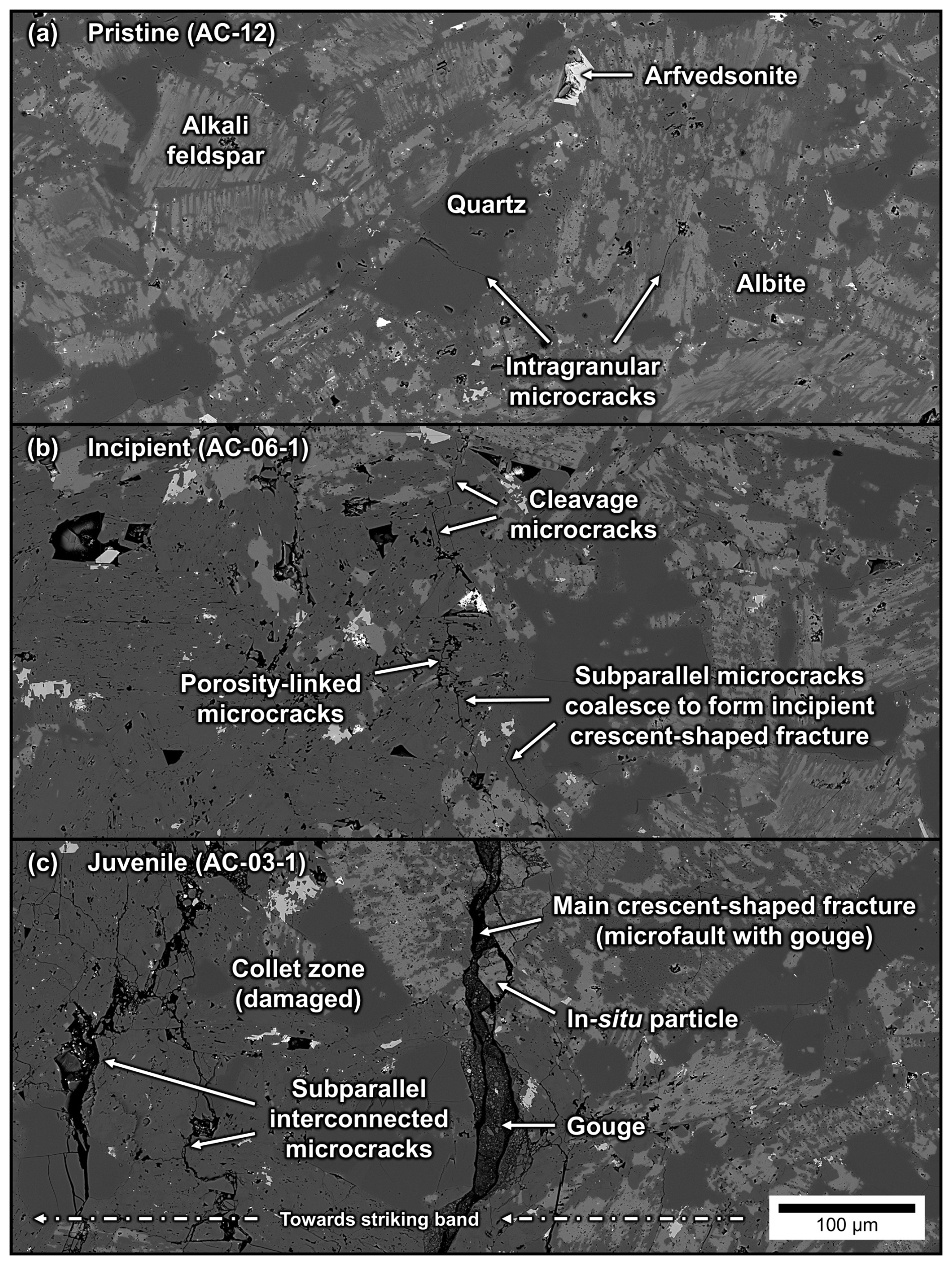
Figure 12Evolution of crescent-shaped fractures and microscale damage in Ailsa Craig Blue Hone curling stones (radial section). (a) Pristine samples contain randomly oriented, pre-existing microcracks. (b) Microcracks form parallel to the striking band and coalesce into an incipient crescent-shaped fracture. (c) The main crescent-shaped fracture widens and evolves into a microfault with visible gouge; a damage zone consisting of interconnected microcracks and microfaults develops in the collet zone between the striking band (direction indicated by arrow) and the main crescent-shaped fracture.
In a sample with incipient damage, the crescent-shaped fracture is characterised by a series of coalescing transgranular microcracks with a maximum width of 0.6 µm (Fig. 12b). Most of the microcracks are flaw-induced and locally take advantage of quartz-alkali feldspar grain boundaries, as well as porosity and cleavages within alkali feldspar. The microcracks are intergranular where they link between microstructural features. Minor incipient damage exists in the collet zone as isolated, subparallel mode 1 fractures. The largest and most common microcracks in the damage zone are intragranular to marginally intergranular, porosity-linked, and/or cleavage microcracks within the alkali feldspar grains. Minor microstructural features include intragranular microcracks within quartz grains and coincident grain-boundary microcracks between quartz and alkali feldspar, which locally extend to form intergranular microcracks.
In a more damaged juvenile sample (Fig. 12c), the main crescent-shaped fracture is expressed as a microfault with larger apertures between 3–45 µm. Importantly, this fracture contains what appear to be domains of fault gouge. This microfault is broadly coincident with quartz–alkali feldspar phase boundaries and grain boundaries between alkali feldspar grains, and can be transgranular through alkali feldspar and quartz grains. However, the coarseness of the microfault generally obscures these microstructural relationships. The gouge within the main crescent-shaped fracture consists of (1) larger (up to 30 µm), locally derived, in-situ fragments, along with (2) smaller particles which have likely been rotated and displaced (Fig. 12c). The larger grains are almost entirely composed of alkali feldspar, whereas smaller grains are a combination of alkali feldspar, quartz, and albite, with rare arfvedsonite and high-field-strength-element minerals (note that among the smaller grains, quartz and albite cannot be distinguished on the basis of their similar SEM-BSE responses). Where the crescent-shaped fracture crosscuts arfvedsonite, the mineral can be found fragmented in the gouge zone, suggesting that the particles are locally derived. The collet zone exhibits a network of apparently subparallel, interconnected intra- and intergranular microcracks (Fig. 12c). These microcracks are heterogeneous and can be further subdivided into several types: (1) flaw-induced, porosity-linked intragranular microcracks in albite; (2) intragranular cleavage microcracks in alkali feldspar and arfvedsonite; (3) flaw-induced, grain-boundary microcracks between alkali feldspar and quartz grains, or among feldspar grains; and (4) conchoidal, intragranular impingement microcracks in quartz grains. Fracture networks are extensively developed in albite, possibly owing to the high degree of porosity within these grains.
Our study explores a particular configuration of cyclical loading in granitoids: hundreds to thousands of impacts with dynamic loading of Hertzian contacts, reaching dynamic stress magnitudes that exceed the quasi-static compressive strengths of the material. This configuration differs from conventional, quasi-static loading and fatigue tests (e.g., Cerfontaine and Collin, 2018), given the higher strain rates and the geometric nature of the Hertzian contacts. Although the strain rates more closely match cyclic dynamic loading tests (i.e., split-Hopkinson pressure bar tests; Aben et al., 2016; Doan and d'Hour, 2012; Braunagel and Griffith, 2019), the configuration differs by (1) the geometry of the contact surfaces (curved versus flat contacts) and resultant heterogeneous stress field evolution; as well as (2) the fact that most of the energy is invested into the unbounded acceleration of the resting stone (see below for discussion), in contrast to dynamic loading experiments, in which the sample is bounded by two bars (the incident and transmitted bars). Nevertheless, the case of curling stone collisions is peculiar in that the stones support these impacts for much longer than cyclical loading tests would suggest.
Determining the impact energy that is invested into the acceleration of the resting stone requires the exact quantification of the initial and final velocities of the moving and stationary stones. Although these were tracked during each experiment using the GoPro cameras, calculations of kinetic energy using these data yielded values of low precision. As a first-order approximation, the high-speed camera experiment no. 2.13 (stone mass 18.41 kg) yielded pre-impact velocities (and kinetic energies in parentheses) of 2.74 m s−1 (69 J) and 0 m s−1 (0 J) for the incoming and stationary stones, respectively. Immediately after the impact, these changed to 0.09 m s−1 (≪1 J) and 2.66 m s−1 (65 J) for the incoming and now-accelerated stone. This implies an energy loss of ∼4 J (∼6 %). This energy loss estimate also includes work done by friction while the stones slide on the ice surface, which represents ∼1 J when applying a coefficient of friction of 0.1 (Nyberg et al., 2013), meaning that ∼3 J or ∼4 % of the impact energy is dissipated in the stone. In the context of natural pheonomena such as earthquakes, estimates of energy dissipation by fracturing vary from 1 % to >50 % (Rockwell et al., 2009; Wilson et al., 2005). At similar strain rates, cyclic split-Hopkinson pressure bar experiments by Xu et al. (2024) recorded an energy absorption between 15 %–25 %, which is much higher than the 4 % calculated for curling stone impacts in this work. These calculations emphasize the dominantly elastic nature of the deformation, where most of the energy is transferred to unbounded motion of the stationary stone, as opposed to producing damage within the rock. Our data indicate that the remaining energy that is not transferred to the motion of the stationary stone is dissipated by propagating crescent-shaped fractures and localizing damage within their collet zones, as well as by ejecting rock powder from the surface of the curling stones.
The aim of this contribution is to explore how damage accumulates in curling stones, and by extension, investigate the effects of dynamic cyclical loading and fatigue on granitoids. In this section, we revisit the original goals of this contribution by (1) determining the boundary conditions of curling stone collisions and (2) describing how crescent-shaped fractures develop in curling stones. We then conclude this section by (3) proposing a conceptual damage evolution model for curling stones that integrates the insights gained from the first two discussion points.
5.1 Boundary conditions of curling stone collisions
In terms of the boundary conditions of curling stone collisions, our results reveal that (1) curling stone impacts produce damage by incurring stresses that exceed the critical fatigue stress of the rocks; (2) that these stresses are significant and comparable to other geological phenomena; and (3) the impacts are dynamic in terms of their stress–strain regimes:
-
Our calculations from on-ice experiments indicate that the dynamic stress magnitudes of the impacts of curling stones (300–680 MPa) exceed the quasi-static uniaxial compressive strength ranges recorded for curling stones (230–520 MPa; Fig. 13; Nichol, 2001; Leung, 2020). Our post-mortem investigation indicates that these impact stresses are responsible for the observed damage. The observation of the dynamic stress exceeding the quasi-static strength of the stones may lead to the incorrect assumption that curling stones should experience failure on one impact. This is because rock strength increases with increasing strain rate, and at the dynamic strain rates of curling stone impacts (), the dynamic strengths of granitoids are typically 1.5–1.9 times higher than their quasi-static strengths (Braunagel and Griffith, 2019; Doan and d'Hour, 2012; Li et al., 2000; Green and Perkins, 1968; Hokka et al., 2016). This implies that the dynamic stresses of curling stone impacts may not actually exceed the expected dynamic strength of the rocks. However, these dynamic stresses likely exceed the threshold required for fatigue damage for repeated loadings at the same stress level (about half of the maximum dynamic compressive strength of a single impact, for strain rates comparable to curling stone impacts; Zhou et al., 2018), thus explaining why damage accumulates in curling stones. It is also important to highlight that dynamic rock strength decreases nearly twofold with cyclic loading (Braunagel and Griffith, 2019; Doan and d'Hour, 2012). This means that once curling stones are damaged by high-velocity impacts, lower-velocity impacts may also contribute to damage accumulation.
-
The stress magnitudes generated by curling stone impacts are comparable to those reached in geological processes and provide an opportunity to study damage evolution resulting from intermediate stress magnitude events. Table 1 shows that the stresses produced by curling stone impacts are larger than those induced by mining as well as those associated with co-seismic rock pulverization. They most closely resemble rockfall stresses. Interestingly, natural, randomly oriented crescent-shaped fractures have been observed on boulders found on the coast of Ailsa Craig (fieldwork conducted by DDVL in September 2020), possibly alluding to the similarity in deformation processes involved in rockfall versus curling stone impacts (Leung, 2020). Crescent-shaped fractures are also common phenomena on glacier-bedrock interfaces, where high stresses emerge from the point loads exerted by boulders in the ice (Harris, 1943; Bestmann et al., 2006; Master, 2012). On the other extreme of stress magnitudes, curling stone impacts produce much lower stresses than ballistic impacts and shock metamorphism.
-
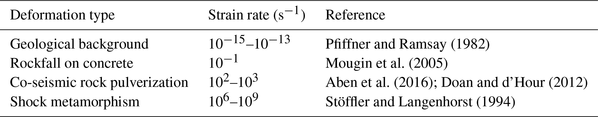
The magnitude of strain rates in curling stone impacts () can be classified as a high strain rate response (Zhang and Zhao, 2014) and suggests that there is a significant dynamic component involved in curling stone impacts. This is corroborated by the ejection of rock powder from the striking bands after impacts between curling stones, as observed by high-speed camera footage. Additionally, the presence of potential spalling microcracks in our post-mortem analysis also supports this interpretation. In terms of strain rate, the closest analogue to curling stone impacts is co-seismic rock pulverization as investigated by cyclic split-Hopkinson pressure bar experiments. These experiments show that the style of failure changes from single fractures to multiple fragments (pulverization) above 85–150 s−1 for previously damaged samples (Doan and d'Hour, 2012; Aben et al., 2016). The lower average elastic strain rate of curling stone impacts calculated by this study generally supports the lack of significant pulverization in curling stones. However, it must be considered that stress and strain are heterogeneous, and their tensorial fields evolve over time and space in curling stone impacts, with stress and strain decaying with distance into the striking band. Thus, the minor amount of pulverized rock powder and spalling microcracks near the surface of the striking band could be related to high local strain rates at the contact surface, although they may also be a product of free-surface effects or associated with damage zones associated with Hertzian contacts (see following section; Padture and Lawn, 1995). In general, the fact that damage originates from the surface of striking bands rather than the center of the curling stone (as in split-Hopkinson pressure bar experiments) indicates that free-surface effects and their associated, heterogeneous stress and strain distributions are expected to have a greater impact on the damage geometry compared to their high strain-rate natures. Nevertheless, our microstructural observations might provide insights into the damage response of seismically loaded granitoids, including pulverization.
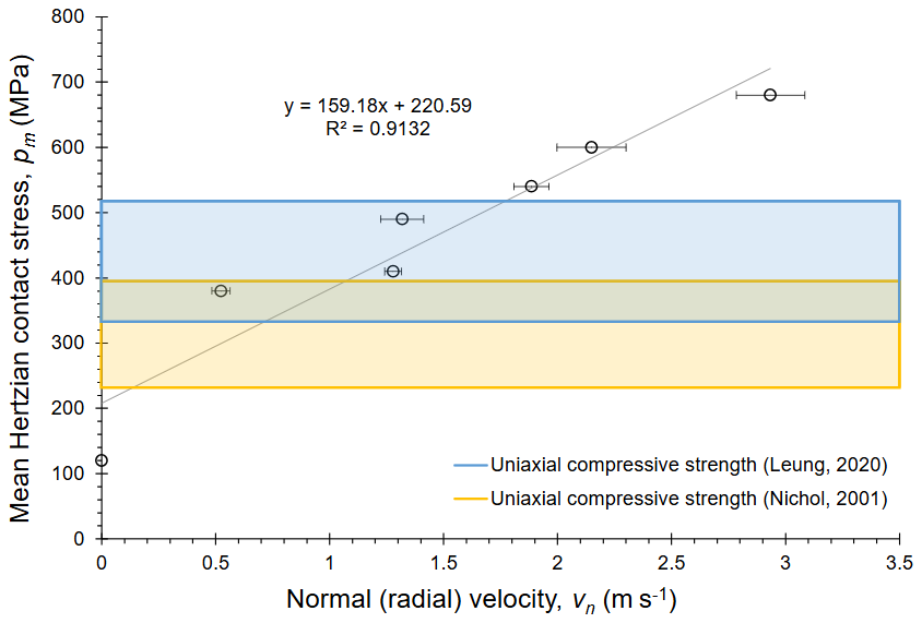
Figure 13The stresses calculated from Hertzian contact analysis show that the high-velocity collisions can generate stresses which exceed the quasi-static uniaxial compressive strengths of the rocks.
Table 1Stress ranges for various types of deformation.
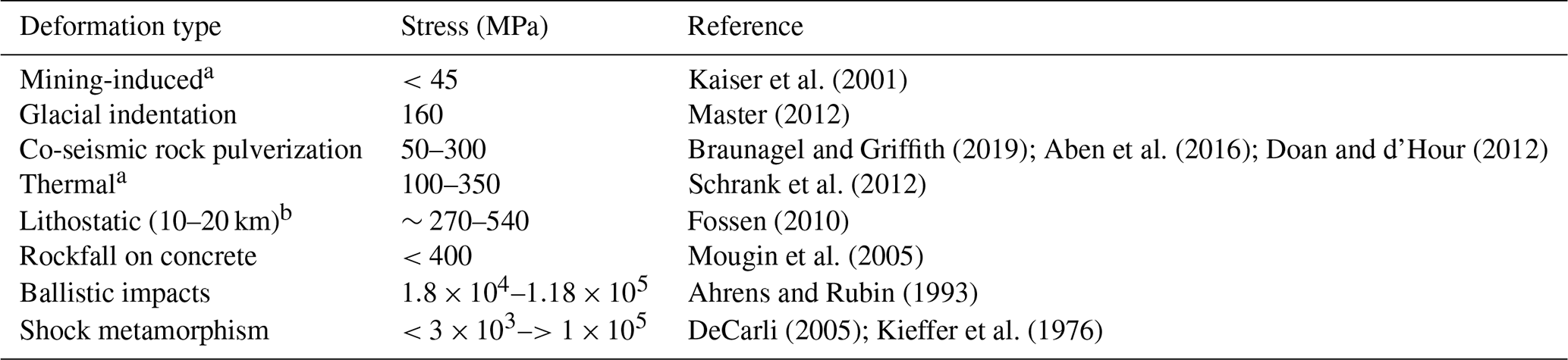
a Quoted stresses represent deviatoric stress ranges.
b Quoted stresses are stress invariants that are only broadly comparable to principal uniaxial stress magnitudes (cf. curling stone impacts).
5.2 Crescent-shaped fractures are Hertzian cone fractures
We interpret crescent-shaped fractures to be Hertzian cone fractures, on the basis of their correlation to the contact areas between colliding curling stones, as well as their conoid morphology. The contact areas measured from the on-ice experiments correlate with the size and shape of the crescent-shaped fractures (Fig. 14a), a feature exhibited by Hertzian cone fractures experimentally produced in other solid media (Fig. 14; Lawn, 1998; Wang et al., 2017). Additionally, the conoid 3D geometry of crescent-shaped fractures is reminiscent of other features interpreted to be Hertzian cone fractures: glacial crescentic gouges (Fig. 14b), percussive fractures from fluvial environments (Fig. 14c–d), as well as experimentally generated fractures in glass (Fig. 14e). Interestingly, the striations present on the surface of crescent-shaped fractures resemble mirror-mist-hackle surface microfracture patterns reported in Hertzian cone fractures in glass (Fig. 14e), which are interpreted to form due to dynamic microcrack propagation (Blenkinsop, 2000; Bahat et al., 2005; Wang et al., 2017). This is yet another line of evidence supporting the dynamic nature of curling stone impacts. Based on the interpretation that crescent-shaped fractures are Hertzian cone fractures, we can use the predicted stress distributions around the Hertzian contacts to understand the observed distribution of microcracks in the striking band, and deduce how damage accumulated to form the crescent-shaped fractures.
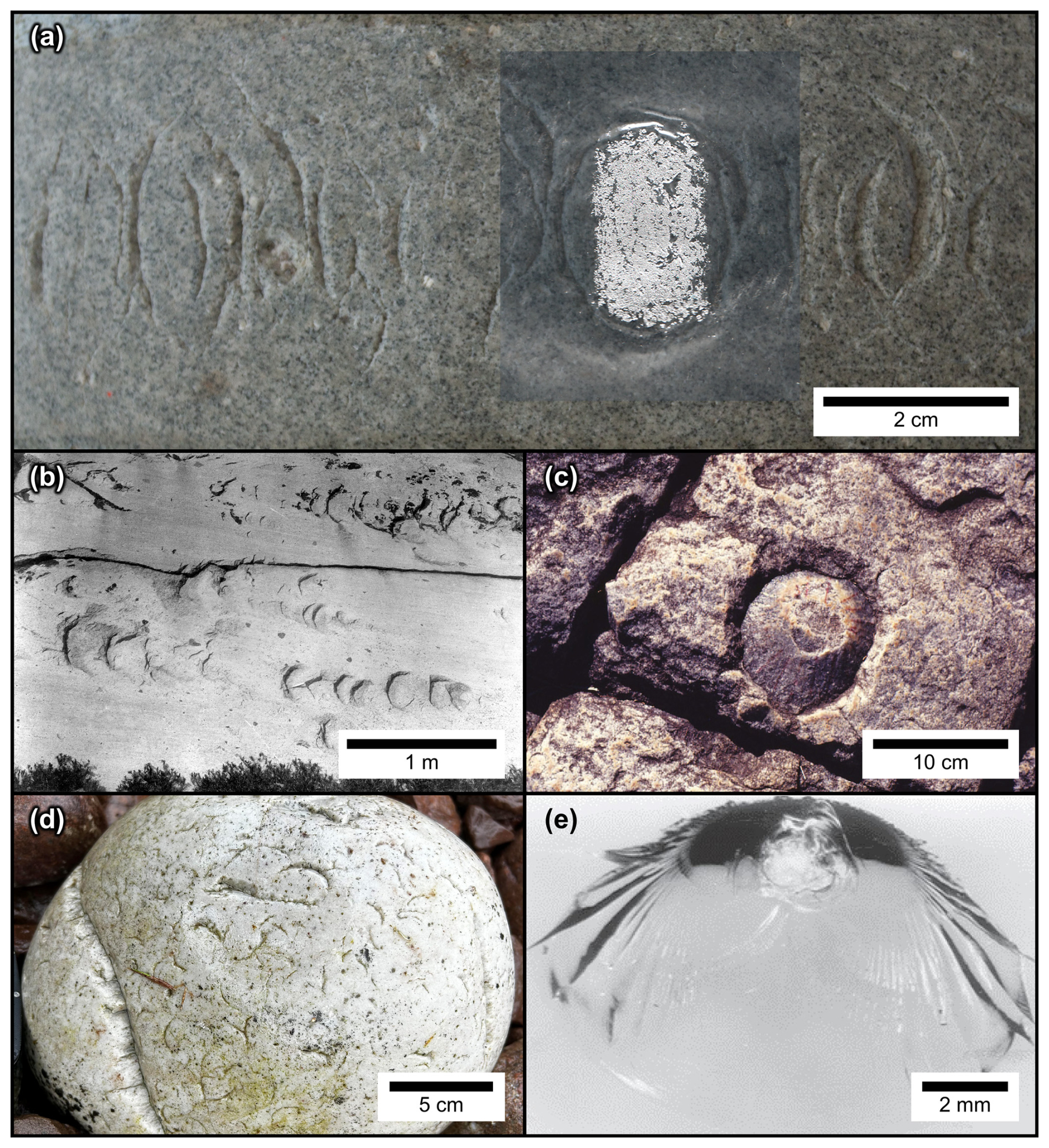
Figure 14(a) Superimposing the contact area from the on-ice experiments (Exp. 1.3) onto an aged striking band (AC-01) shows the resemblance in shape and size between the contact areas and crescent-shaped fractures, suggesting that crescent-shaped fractures are Hertzian cone fractures. (b–e) Examples of natural and antropogenic Hertzian cone fractures. (b) Glacial crescentic gouges (a subclass of chatter marks) produced by point loading of erratics via glacial transport, Sierra Nevada, CA, USA (from Gilbert, 1906). (c) Percussive fractures produced by point loading of boulders in a fluvial environment (paleowaterfall), eastern circumference of Bushveld Complex, South Africa (from Baratoux and Reimold, 2016. © 1999–2026 John Wiley & Sons, Inc. All rights reserved. See also Reimold and Minnitt, 1996). (d) Cobblestone showing abundant crescent percussion marks formed during weathering and transport, Culkein, NW Scotland, United Kingdom. (e) Experimentally generated Hertzian cone fractures in glass; note the presence of mirror-mist-hackle structures on the surface of the cone fracture (from Wang et al., 2017, © 2026 Elsevier B.V. All rights reserved).
The conoid 3D geometry of Hertzian cone fractures as displayed by crescent-shaped fractures follows a path that maximizes the strain energy release during the impact (Kocer and Collins, 1998) and is broadly parallel to the stress trajectories of the maximum compressive stress component (Frank and Lawn, 1967), which correlates to the stress component measured in the on-ice experiments. The crescent-shaped fractures in our samples nucleate as intragranular cleavage cracks in feldspars that are oriented parallel to the predicted maximum compressive stress trajectories produced by Hertzian contacts, which subsequently link to form transgranular cracks. Similarly, in cyclical loading experiments, microcracks form with a preferential alignment parallel to the maximum compressive strength component, and the linking of intragranular cleavage cracks in feldspars represents the onset of unstable crack propagation (Chen et al., 2011; Akesson et al., 2004).
These initial damage structures are created by early, high-velocity collisions and are controlled by the stress field trajectories of Hertzian contacts, with subsequent impacts propagating these initial damage structures. The early onset of these damage structures is evident from our observations during the on-ice experiments: the stones used in the experiment had been played for less than a season, yet they already displayed weakly incipient crescent-shaped fractures (Fig. 5). Furthermore, our post-mortem analyses show that the density of crescent-shaped fractures becomes saturated in the incipient stage of damage and does not increase towards the mature stage of damage. These observations are supported by acoustic emissions data recording cyclic loading experiments by Sondergeld and Estey (1981), which show that (1) the majority of acoustic emission events occur in the first cycle of loading, with fewer acoustic emission events in later cycles, and (2) acoustic emission hypocenters cluster around previous hypocenters. Additionally, findings from Ostermeijer et al. (2022) further support the concept that damage zones can dissipate energy and protect undamaged regions from accumulating damage. The implication is that significant damage structures are created during early collisions, with subsequent collisions propagating these damage structures. That is, the stresses are dampened by energy dissipation in the damage zone by utilizing pre-existing structures, rather than forming new ones.
All of these observations closely resemble the damage observed in cyclic Hertzian indentation experiments on silicon carbide ceramics with homogeneous grain sizes (Fig. 15; Padture and Lawn, 1995), where (1) an initial cone fracture forms during the first indentation cycle, then (2) a damage zone develops in the collet zone over 100–10 000 cycles, and (3) material is ejected from the collet zone over 10 000–1 000 000 cycles (cf. exfoliation in the collet zone of crescent-shaped fractures). Similar to our observations, it is shown that damage is largely restricted to the Hertzian cone fractures and their associated collet zones, with virtually no damage outside of these areas. There are two notable differences in damage geometry between curling stone impacts and cyclic Hertzian indentation experiments that can be attributed to the nature and orientation of these collisions. First, the cone fractures in Padture and Lawn (1995) consist of closed forms (i.e., circles) on the material surface, whereas crescent-shaped fractures are open forms (i.e., crescents). As most curling stone collisions do not occur exactly head on (cf. normal loading in cyclic Hertzian indentation experiments), there is a tangential stress component of loading analogous to the directionality of glacial crescentic gouges (Gilbert, 1906). Second, the damage zone in curling stone collisions consists of fractures that are oblique to the main crescent-shaped fracture (Fig. 7), whereas those in Padture and Lawn (1995) are concentric and parallel to the main Hertzian cone fracture. Unlike the cyclic experiments where the impact area is fixed, the location of curling stone impacts is distributed along the equatorial striking band, meaning that the collisions will not occur on exactly the same area as previous collisions. In summary, almost all of the damage features visible in curling stone impacts can be attributed to cyclic loading of Hertzian contacts, and this forms the basis for our conceptual model for damage evolution in curling stones.
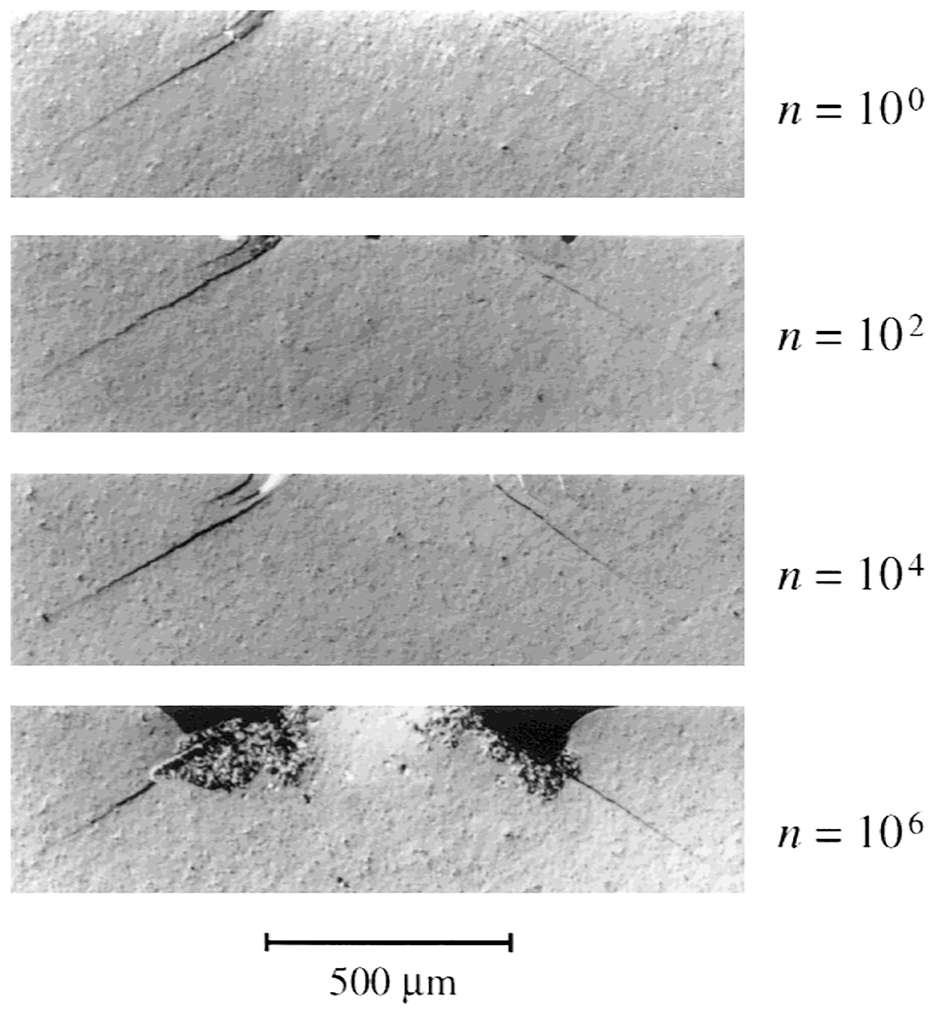
Figure 15Damage evolution of silicon carbide ceramics with homogeneous grain sizes under cyclical spherical indentation (radius = 3.18 mm, force = 1000 N, frequency = 10 Hz) under Nomarski interference, n = number of loading cycles. From Padture and Lawn (1995); Lawn (1998). © 1999–2026 John Wiley & Sons, Inc. All rights reserved.
5.3 Conceptual model for damage evolution in curling stones
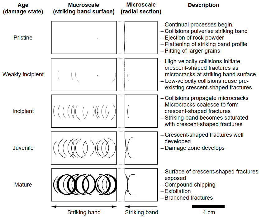
We return to rock mechanics by proposing a multiscale damage evolution model of curling stones, which takes into account the cyclical damage conditions of curling stone impacts, as well as the macroscopic and microscopic damage features observed in curling stones (Fig. 16). The damage evolution of curling stones consists of several damage states: pristine, weakly incipient, incipient, juvenile, and mature.
Pristine stage. At the macroscale, no crescent-shaped fractures are visible. However, repeated curling stone impacts pulverize the surface of the striking band, resulting in the ejection of rock powder, progressive flattening of the striking band, and pitting. The flattening of the striking band occurs at the scale of ten to fifteen years with average use (largely within the pristine to incipient damage states), which coincides with the maintenance cycle of re-profiling curling stones. The duration of the pristine stage varies by rock type: some retired Blue Trefor curling stones have apparently remained in the pristine stage, whereas early stage evidence of crescent-shaped fractures has been recorded within less than a season of play in Ailsa Craig Common Green stones.
Weakly incipient stage. At the macroscale, the damage is difficult to discern but is characterised by sparse, partially developed, curvilinear discolouration features. Initially, high-velocity impacts initiate Hertzian cone fractures, whereas low-velocity impacts may propagate existing fractures. At the microscale, microcracks (mostly intragranular within feldspars) are distributed parallel to the predicted stress trajectories produced by Hertzian contacts.
Incipient stage. At the macroscale, crescent-shaped fractures are partially developed and are relatively visible, despite showing minimal topographic relief. The striking band is saturated with crescent-shaped fractures, so succeeding impacts propagate existing crescent-shaped fractures instead of creating new fractures. At the microscale, transgranular microcracks propagate to form through-going crescent-shaped fractures. A few microcracks mark a proto-damage zone between the striking band and the main crescent-shaped fracture.
Juvenile stage. At the macroscale, crescent-shaped fractures are well defined and develop topographic relief. Succeeding impacts cause crescent-shaped fractures to penetrate deeper into the curling stone, and a localised damage zone develops in the collet zone between the striking band and the crescent-shaped fractures. At the microscale, the crescent-shaped fractures widen to become through-going microfaults with gouge and continue to propagate at the margins of the fractures and into the stone. The damage zone consists of interconnected transgranular fractures.
Mature stage. At the macroscale, the fracture surface of crescent-shaped fractures is exposed on the striking band due to the ejection of material from the damage zone. As a result, the striking band becomes irregular and locally concave. Secondary structures such as compound chipping, exfoliation, and branched fractures develop. At the microscale, crescent-shaped fractures are expected to propagate deeper into the curling stone, while the damage zone grows laterally. Most curling stones are re-profiled or replaced before reaching this stage.
In this contribution, we have shown that curling stones are momentarily stressed to 300–680 MPa for high-velocity impacts (), exceeding the threshold for fatigue damage during dynamic loading. The impacts are shown to be dynamic in nature, as evidenced by (1) high strain rates () that approach those of co-seismic rock pulverization; (2) the ejection of rock powder as observed by the on-ice experiments; and (3) the presence of striations on crescent-shaped fractures that are interpreted to have formed by dynamic microfracture propagation (mirror-mist-hackle pattern). Crescent-shaped fractures are interpreted to be Hertzian cone fractures on the basis of their relationship to contacts between colliding curling stones, as well as their conoid morphology that is reminiscent of Hertzian cone fractures observed in other natural and engineered materials. We interpret crescent-shaped fractures to develop early via high-velocity impacts, in which damage initiates mainly as intragranular microcracks in feldspars, which propagate into transgranular microcracks that eventually develop into through-going microfaults as crescent-shaped fractures. Subsequent impacts propagate these and coarsen crescent-shaped fractures, and a localized damage zone develops in the collet between the crescent-shaped fractures and the striking band.
This work has several limitations that could be expanded through future work. Most critically, the approaches used to estimate the stress and strain of the impacts are oversimplified and do not take into account that stress propagates as waves at the p-wave velocity of the material. This leads to stress, strain, and strain-rate fields being heterogeneous and evolving with time and space. Future efforts in modelling the dynamic stresses will be able to address the potential for heterogeneous, evolving stresses as a possible mechanism for damage. Along these lines, experiments on the dynamic strength of curling stones would better place curling stone impacts within the context of natural deformation processes. With respect to curling stones, four different varieties exist (Ailsa Craig Blue Hone, Ailsa Craig Common Green, Blue Trefor, and Red Trefor), but their mechanical behaviors were not differentiated in this contribution. As such, further work is warranted to differentiate the dynamic behaviors of different curling stone types in order to understand how mineralogy and grain-size distribution influence the mechanical properties of granitoids, as well as how this leads to the accumulation of damage during repeated dynamic and Hertzian loading (e.g., Leung, 2020; Leung and McDonald, 2022; Padture and Lawn, 1995).
Files S1–S5 can be found on Zenodo: https://doi.org/10.5281/zenodo.17902451 (Leung et al., 2025). File S1 corresponds to GoPro image processing steps. File S2 corresponds to GoPro uncertainty analysis. File S3 corresponds to probability thresholds for image segmentation of sample AC-03-1. File S4 corresponds to kinematic and contact-area data for the on-ice experiments. File S5 contains the Matlab® script used to calculate Hertzian contact stresses.
Video S1 contains the high-speed camera footage and can be found on Zenodo: https://doi.org/10.5281/zenodo.17902451 (Leung et al., 2025).
Contributions follow the CRediT model. DDVL: conceptualization, data curation, formal analysis, funding acquisition, investigation, methodology, project administration, resources, visualization, writing – original draft, writing – review and editing. FF: conceptualization, funding acquisition, supervision, writing – review and editing. IBB: conceptualization, funding acquisition, methodology, resources, supervision, writing – review and editing.
At least one of the (co-)authors is a member of the editorial board of Solid Earth. The peer-review process was guided by an independent editor, and the authors also have no other competing interests to declare.
Publisher's note: Copernicus Publications remains neutral with regard to jurisdictional claims made in the text, published maps, institutional affiliations, or any other geographical representation in this paper. The authors bear the ultimate responsibility for providing appropriate place names. Views expressed in the text are those of the authors and do not necessarily reflect the views of the publisher.
This contribution originates from an M.Sc.R. thesis completed by Derek D. V. Leung at the University of Edinburgh. Synchrotron data were collected at Diamond Light Source (Oxfordshire, UK) under beamtime proposal MG22517 and Advanced Photon Source (Lemont, IL) under proposal 81226. Canada Curling Stone Co and Andrew Kay & Co Ltd are thanked for providing samples and in-kind contributions. Adam Griffiths, Terry Williams, and Bryn Griffith are thanked for providing access to the Trefor quarry. The late Mark McCrindle is thanked for his logistical assistance in visiting Ailsa Craig. Mike Boyd and Anthony Middleton (UCreate Studio, University of Edinburgh) are thanked for providing access to photogrammetry and electronics equipment. Andy Macpherson and Scott Henderson (Curl Edinburgh) are thanked for providing ice time for the on-ice experiments. Mark Johnson (Slowmo Ltd) and Alan Woolley (University of Edinburgh) provided access to high-speed cameras and lighting for the on-ice experiments. Bruce Mouat, Berit Schwichtenberg, and Dylan Price are thanked for their assistance with on-ice experiments. Nicola Cayzer (University of Edinburgh) assisted with SEM analyses. Godfrey Fitton (University of Edinburgh) and Alexis Cartwright-Taylor (University of Edinburgh/Herriot-Watt University) are thanked for their mentorship and support. Stephane Perrouty (Laurentian University) is thanked for access to a computer workstation for processing the SµCT data. Eranga Jayawickrama (RWTH Aachen University) is thanked for discussions relating to split-Hopkinson pressure bar experiments.
Derek D. V. Leung was supported by the Scotland Saltire Scholarship, Mineralogical Association of Canada Foundation Scholarship, Young Mining Professionals Yamana Gold Student in Mining Scholarship, and Gem and Mineral Club of Scarborough Jennifer and Blair Campbell Bursary. Research funding was supported by the Moray Endowment Fund, Edinburgh Geological Society, and the NERC CATFAIL project (NE/R001693/1). Fieldwork on Ailsa Craig was supported by the Mykura Fund from the Edinburgh Geological Society.
This open-access publication was funded by the RWTH Aachen University.
This paper was edited by Jessica McBeck and reviewed by Elma Charalampidou and one anonymous referee.
Aben, F. M., Doan, M.-L., Mitchell, T. M., Toussaint, R., Reuschlé, T., Fondriest, M., Gratier, J.-P., and Renard, F.: Dynamic fracturing by successive coseismic loadings leads to pulverization in active fault zones, J. Geophys. Res.-Sol. Ea., 121, 2338–2360, https://doi.org/10.1002/2015JB012542, 2016. a, b, c, d
Aben, F. M., Doan, M.-L., Gratier, J.-P., and Renard, F.: Coseismic Damage Generation and Pulverization in Fault Zones, Chap. 4, American Geophysical Union (AGU), 47–80, https://doi.org/10.1002/9781119156895.ch4, 2017. a
Ahrens, T. J. and Rubin, A. M.: Impact-induced tensional failure in rock, J. Geophys. Res.-Planets, 98, 1185–1203, https://doi.org/10.1029/92JE02679, 1993. a
Akesson, U., Hansson, J., and Stigh, J.: Characterisation of microcracks in the Bohus granite, western Sweden, caused by uniaxial cyclic loading, Eng. Geol., 72, 131–142, https://doi.org/10.1016/j.enggeo.2003.07.001, 2004. a
AliceVision: Meshroom: A 3D reconstruction software, https://github.com/alicevision/meshroom (last access: 21 November 2020), 2018. a
Arganda-Carreras, I., Kaynig, V., Rueden, C., Eliceiri, K. W., Schindelin, J., Cardona, A., and Sebastian Seung, H.: Trainable Weka Segmentation: a machine learning tool for microscopy pixel classification, Bioinformatics, 33, 2424–2426, https://doi.org/10.1093/bioinformatics/btx180, 2017. a
Bahat, D., Rabinovitch, A., and Frid, V.: Tensile fracturing in rocks, Springer, https://doi.org/10.1007/b137741, 2005. a
Baratoux, D. and Reimold, W. U.: The current state of knowledge about shatter cones: Introduction to the special issue, Meteoritics & Planetary Science, 51, 1389–1434, https://doi.org/10.1111/maps.12678, 2016. a
Barber, J.: Contact Mechanics, Solid Mechanics and Its Applications, Springer International Publishing, https://books.google.co.uk/books?id=4GNLDwAAQBAJ, 2018. a, b
Bestmann, M., Rice, A., Langenhorst, F., Grasemann, B., and Heidelbach, F.: Subglacial bedrock welding associated with glacial earthquakes, J. Geol. Soc. London, 163, 417–420, https://doi.org/10.1144/0016-764920-164, 2006. a
Blenkinsop, T. G.: Deformation Microstructures and Mechanisms in Minerals and Rocks, Springer Netherlands, Dordrecht, https://doi.org/10.1007/0-306-47543-X, 2000. a, b
Braunagel, M. J. and Griffith, W. A.: The Effect of Dynamic Stress Cycling on the Compressive Strength of Rocks, Geophys. Res. Lett., 46, 6479–6486, https://doi.org/10.1029/2019GL082723, 2019. a, b, c, d
Cartwright-Taylor, A., Main, I. G., Butler, I. B., Fusseis, F., Flynn, M., and King, A.: Catastrophic Failure: How and When? Insights From 4-D In Situ X-ray Microtomography, J. Geophys. Res.-Sol. Ea., 125, e2020JB019642, https://doi.org/10.1029/2020JB019642, 2020. a
Cerfontaine, B. and Collin, F.: Cyclic and Fatigue Behaviour of Rock Materials: Review, Interpretation and Research Perspectives, Rock Mechanics and Rock Engineering, https://doi.org/10.1007/S00603-017-1337-5, 2018. a
Chen, Y., Watanabe, K., Kusuda, H., Kusaka, E., and Mabuchi, M.: Crack growth in Westerly granite during a cyclic loading test, Eng. Geol., 117, 189–197, https://doi.org/10.1016/j.enggeo.2010.10.017, 2011. a
DeCarli, P.: Shock metamorphism, in: Encyclopedia of Geology, edited by: Selley, R. C., Cocks, L. R. M., and Plimer, I. R., Elsevier, Oxford, 179–184, https://doi.org/10.1016/B0-12-369396-9/00323-3, 2005. a
Doan, M.-L. and d'Hour, V.: Effect of initial damage on rock pulverization along faults, J. Struct. Geol., 45, 113–124, https://doi.org/10.1016/j.jsg.2012.05.006, 2012. a, b, c, d, e, f
Fossen, H.: Structural Geology, Cambridge University Press, https://doi.org/10.1017/CBO9780511777806, 2010. a
Frank, F. C. and Lawn, B. R.: On the theory of Hertzian fracture, Proceedings of the Royal Society of London. Series A. Mathematical and Physical Sciences, 299, 291–306, https://doi.org/10.1098/rspa.1967.0137, 1967. a
Gilbert, G. K.: Crescentic gouges on glaciated surfaces, GSA Bulletin, 17, 303–316, https://doi.org/10.1130/GSAB-17-303, 1906. a, b
Green, S. and Perkins, R.: Uniaxial Compression Tests At Varying Strain Rates On Three Geologic Materials, 10th U.S. Symposium on Rock Mechanics (USRMS) of U.S. Rock Mechanics/Geomechanics Symposium, Austin, Texas, 20–22 May 1968, ARMA-68-0035, 1968. a
Harris, S. E.: Friction Cracks and the Direction of Glacial Movement, J. Geol., 51, 244–258, https://doi.org/10.1086/625148, 1943. a
Hokka, M., Black, J., Tkalich, D., Fourmeau, M., Kane, A., Hoang, N.-H., Li, C., Chen, W., and Kuokkala, V.-T.: Effects of strain rate and confining pressure on the compressive behavior of Kuru granite, Int. J. Impact Eng., 91, 183–193, https://doi.org/10.1016/j.ijimpeng.2016.01.010, 2016. a
Kaiser, P., Yazici, S., and Maloney, S.: Mining-induced stress change and consequences of stress path on excavation stability – a case study, Int. J. Rock Mech. Min., 38, 167–180, https://doi.org/10.1016/S1365-1609(00)00038-1, 2001. a
Kieffer, S. W., Phakey, P. P., and Christie, J. M.: Shock processes in porous quartzite: Transmission electron microscope observations and theory, Contributions to Mineralogy and Petrology, 59, 41–93, https://doi.org/10.1007/BF00375110, 1976. a
Kocer, C. and Collins, R. E.: Angle of Hertzian Cone Cracks, Journal of the American Ceramic Society, 81, 1736–1742, https://doi.org/10.1111/j.1151-2916.1998.tb02542.x, 1998. a
Lawn, B. R.: Indentation of Ceramics with Spheres: A Century after Hertz, Journal of the American Ceramic Society, 81, 1977–1994, https://doi.org/10.1111/j.1151-2916.1998.tb02580.x, 1998. a, b
Leung, D. D. V.: Taking rocks for granite: An integrated mineralogical, textural, and petrographic baseline of curling stones used in international-level competition, B.Sc. thesis, Laurentian University, Canada, 2019. a
Leung, D. D. V.: Where curling collides with rock physics: Characterising the damage evolution of curling stones, M.Sc.R thesis, University of Edinburgh, United Kingdom, 2020. a, b, c, d, e, f
Leung, D. D. V.: Author Comment 1, Reply to RC1, https://doi.org/10.5194/egusphere-2025-3499-AC1, 2025. a, b, c
Leung, D. D. V., Fusseis, F., and Butler, I. B.: Supplement for Leung et al. “Where curling collides with rock mechanics: Cyclical damage accumulation and fatigue in granitoids”, Zenodo [data set and video], https://doi.org/10.5281/zenodo.17902451, 2025. a, b, c, d, e, f, g, h
Leung, D. D. V. and McDonald, A. M.: Taking Rocks for Granite: An Integrated Geological, Mineralogical, and Textural Study of Curling Stones Used in International Competition, Can. Mineral., 60, 171–199, https://doi.org/10.3749/canmin.2100052, 2022. a, b, c, d
Li, H., Zhao, J., and Li, T.: Micromechanical modelling of the mechanical properties of a granite under dynamic uniaxial compressive loads, Int. J. Rock Mech. Min., 37, 923–935, https://doi.org/10.1016/S1365-1609(00)00025-3, 2000. a
Ling, S. J., Sanny, J., and Moebs, W.: University Physics, Vol. 1, OpenStax, Rice University, ISBN-13 978-1-947172-20-3, 2018. a, b, c
Master, S.: Hertzian fractures in the sub-Dwyka Nooitgedacht Striated pavement, and implications for the former thickness of Karoo strata near Kimberley, South Africa, South African Journal of Geology, 115, 561–576, https://doi.org/10.2113/gssajg.115.4.561, 2012. a, b
Moore, D. E. and Lockner, D.: The role of microcracking in shear-fracture propagation in granite, J. Struct. Geol., 17, 95–114, 1995. a
Moore, D. E., Morrow, C. A., and Byerlee, J. D.: Fluid-rock interaction and fracture development in “crystalline” rock types, Tech. rep., U. S. Geological Survey, https://doi.org/10.3133/ofr87279, 1987. a
Mougin, J.-P., Perrotin, P., Mommessin, M., Tonnelo, J., and Agbossou, A.: Rock fall impact on reinforced concrete slab: An experimental approach, Int. J. Impact Eng., 31, 169–183, https://doi.org/10.1016/j.ijimpeng.2003.11.005, 2005. a, b
Nemat-Nasser, S., Isaacs, J. B., and Starrett, J. E.: Hopkinson techniques for dynamic recovery experiments, Proceedings of the Royal Society of London. Series A: Mathematical and Physical Sciences, 435, 371–391, https://doi.org/10.1098/rspa.1991.0150, 1991. a
Nichol, D.: Ornamental granite from Ailsa Craig, Scotland, The Journal of Gemmology, 27, 286–290, 2001. a
Nikitin, V.: TomocuPy – efficient GPU-based tomographic reconstruction with asynchronous data processing, Journal of Synchrotron Radiation, 30, 179–191, https://doi.org/10.1107/S1600577522010311, 2023. a
Nyberg, H., Alfredson, S., Hogmark, S., and Jacobson, S.: The asymmetrical friction mechanism that puts the curl in the curling stone, Wear, 301, 583–589, 2013. a
Ostermeijer, G. A., Aben, F. M., Mitchell, T. M., Rockwell, T. K., Rempe, M., and Farrington, K.: Evolution of co-seismic off-fault damage towards pulverisation, Earth Planet. Sc. Lett., 579, 117353, https://doi.org/10.1016/j.epsl.2021.117353, 2022. a
Padture, N. P. and Lawn, B. R.: Contact Fatigue of a Silicon Carbide with a Heterogeneous Grain Structure, Journal of the American Ceramic Society, 78, 1431–1438, https://doi.org/10.1111/j.1151-2916.1995.tb08834.x, 1995. a, b, c, d, e, f
Pfiffner, O. A. and Ramsay, J. G.: Constraints on geological strain rates: Arguments from finite strain states of naturally deformed rocks, J. Geophys. Res.-Sol. Ea., 87, 311–321, https://doi.org/10.1029/JB087iB01p00311, 1982. a
Reimold, W. and Minnitt, R.: Impact-induced shatter cones or percussion marks on quartzites of the Witwatersrand and Transvaal Supergroups?, South African Journal of Geology, 99, 299–308, 1996. a
Rockwell, T., Sisk, M., Girty, G., Dor, O., Wechsler, N., and Ben-Zion, Y.: Chemical and Physical Characteristics of Pulverized Tejon Lookout Granite Adjacent to the San Andreas and Garlock Faults: Implications for Earthquake Physics, Pure Appl. Geophys., 166, 1725–1746, https://doi.org/10.1007/s00024-009-0514-1, 2009. a
Schindelin, J., Arganda-Carreras, I., Frise, E., Kaynig, V., Longair, M., Pietzsch, T., Preibisch, S., Rueden, C., Saalfeld, S., Schmid, B., Tinevez, J.-Y., White, D. J., Hartenstein, V., Eliceiri, K., Tomancak, P., and Cardona, A.: Fiji: an open-source platform for biological-image analysis, Nature Methods, 9, 676–682, 2012. a, b, c, d, e, f, g
Schrank, C. E., Fusseis, F., Karrech, A., and Regenauer-Lieb, K.: Thermal-elastic stresses and the criticality of the continental crust, Geochem. Geophy. Geosy., 13, https://doi.org/10.1029/2012GC004085, 2012. a
Sondergeld, C. H. and Estey, L. H.: Acoustic emission study of microfracturing during the cyclic loading of westerly granite, J. Geophys. Res.-Sol. Ea., 86, 2915–2924, https://doi.org/10.1029/JB086iB04p02915, 1981. a
Stöffler, D. and Langenhorst, F.: Shock metamorphism of quartz in nature and experiment: I. Basic observation and theory, Meteoritics, 29, 155–181, https://doi.org/10.1111/j.1945-5100.1994.tb00670.x, 1994. a
Voorn, M., Exner, U., and Rath, A.: Multiscale Hessian fracture filtering for the enhancement and segmentation of narrow fractures in 3D image data, Comput. Geosci., 57, 44–53, https://doi.org/10.1016/j.cageo.2013.03.006, 2013. a, b
Wang, X., Yang, J., Liu, Q.-f., Zhang, Y.-M., and Zhao, C.: A comparative study of numerical modelling techniques for the fracture of brittle materials with specific reference to glass, Engineering Structures, 152, 493–505, https://doi.org/10.1016/j.engstruct.2017.08.050, 2017. a, b, c
Wilson, B., Dewers, T., Reches, Z., and Brune, J.: Particle size and energetics of gouge from earthquake rupture zones, Nature, 434, 749–752, https://doi.org/10.1038/nature03433, 2005. a
World Curling Federation: The rules of curling and rules of competition, October, 2018. a
Xu, H., Rong, C., Wang, B., Zhang, Q., Shen, Z., and Jin, Y.: Dynamic mechanical behavior and energy dissipation characteristics of low-temperature saturated granite under cyclic impact loading, Scientific Reports, 14, 26840, https://doi.org/10.1038/s41598-024-74059-3, 2024. a
Zhang, Q. and Zhao, J.: A Review of Dynamic Experimental Techniques and Mechanical Behaviour of Rock Materials, Rock Mechanics and Rock Engineering, 47, https://doi.org/10.1007/s00603-013-0463-y, 2014. a, b
Zhou, T., Dong, S. L., Zhao, G. F., Zhang, R., Wu, S. Y., and Zhu, J. B.: An Experimental Study of Fatigue Behavior of Granite Under Low-Cycle Repetitive Compressive Impacts, Rock Mechanics and Rock Engineering, 51, 3157–3166, https://doi.org/10.1007/s00603-018-1515-0, 2018. a