the Creative Commons Attribution 4.0 License.
the Creative Commons Attribution 4.0 License.
 | 30 Apr 2021
Emplacement of “exotic” Zechstein slivers along the inverted Sontra Graben (northern Hessen, Germany): clues from balanced cross sections and geometrical forward modeling
Jakob Bolz
Jonas Kley
Lens-shaped slivers of Permian (Zechstein) amid Triassic units appearing along the master fault of the Sontra Graben in central Germany on the southern margin of the Central European Basin System (CEBS) were studied by means of detailed map analysis, a semi-quantitative forward model, and two balanced cross sections. We show how partial reactivation of the graben's main normal fault and shortcut thrusting in the footwall during inversion, combined with a specific fault geometry involving flats in low-shear-strength horizons, can produce the observed slivers of “exotic” Zechstein. This conceptual model implies that the Sontra Graben was created by about 1200 m of extension followed by some 1000 m of contraction, resulting in the few hundred meters of net extension observed today. Gentle dips and comparatively extensive exposure of some slivers suggest they are backthrust onto the reactivated normal fault's hanging wall, an interpretation corroborated in one location by shallow drilling. Backthrusting appears to have wedged some Zechstein slivers into incompetent Triassic units of the hanging wall. Based on regional correlation, extension most likely occurred in Late Triassic to Early Cretaceous time, while the contraction is almost certainly of Late Cretaceous age. The main aim of this paper is to describe an uncommon structural feature that we interpret to originate from inversion tectonics in an evaporite-bearing succession with multiple detachment horizons but without the presence of thick salt.
- Article
(22067 KB) - Full-text XML
-
Supplement
(46 KB) - BibTeX
- EndNote


The Mesozoic tectonic evolution of central Europe involved intermittent Triassic to Early Cretaceous extension followed by a short-lived pulse of mostly Late Cretaceous contractional deformation. This history is best documented by subsidence and inversion in the main sub-basins of the Central European Basin System (CEBS) such as the Broad Fourteens, Lower Saxony, and Polish basins (Brochwicz-Lewiński and Poźaryski, 1987; Hooper et al., 1995; Mazur et al., 2005; Maystrenko and Scheck-Wenderoth, 2013). In Germany, a wide southern border zone of the CEBS also experienced a first distributed extension of low magnitude and then equally dispersed contraction. These movements created an array of narrow grabens and half-grabens affected to different degrees by folding and thrusting. The grabens or fault zones are the most prominent structures in the otherwise flat-lying to gently undulating Mesozoic cover of the central German uplands (Mittelgebirge). They exhibit two prevailing strike directions: NW–SE and N–S to NNE–SSW, with the former considerably more frequent than the latter. The Sontra Graben discussed here is one of the NW–SE-trending Hessian grabens. It is located in the northeastern part of the state of Hessen, approximately 50 km south of the city of Göttingen (Fig. 1). The Hessian grabens appear as narrow strips of Middle to Late Triassic (Muschelkalk and Keuper; see Menning, 2018, for exact age assignments) strata, downfaulted by as much as several hundreds of meters relative to their Early Triassic (Buntsandstein) surroundings. Despite their designation as “grabens”, which was coined in the early 20th century (e.g., Schröder, 1925) and persists in their names today, many of them show a pronounced asymmetry, having one boundary fault with considerably larger displacement than the other. The structures of the (half-)graben interiors are highly variable, ranging from gentle synclines over successions of synclines and anticlines to rotated, fault-bounded blocks.
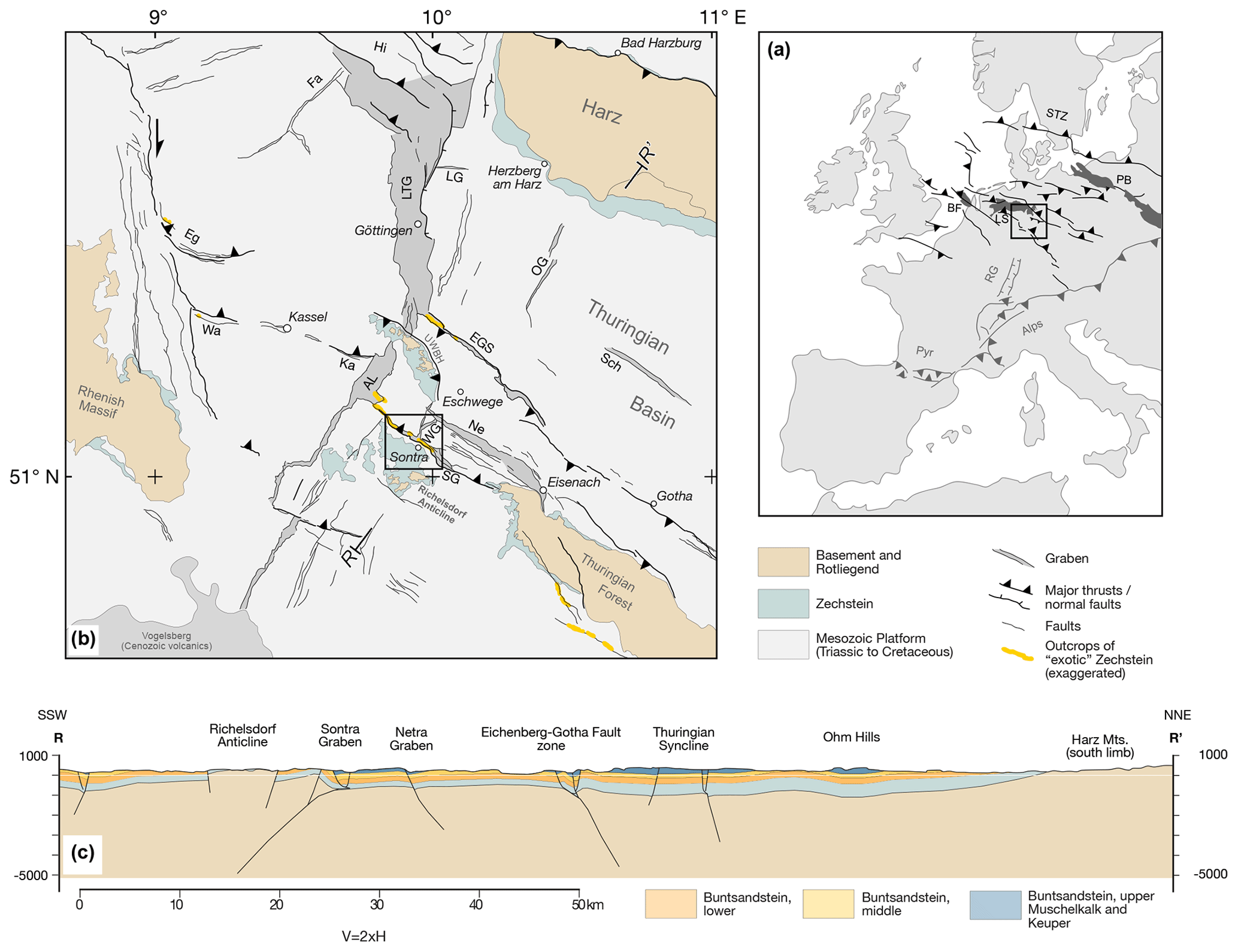
Figure 1(a) Overview of the Central European Basin System (CEBS). The black box indicates the extent of (b). (b) Basin architecture of the southern extent of the CEBS. Modified from Kley (2013) and the sources indicated therein. The black box indicates the study area, shown in greater detail in Fig. 4. (c) Regional cross section showing the main basement structures and the relation to the overlying sedimentary cover in the area. Section trace (R–R′) is shown in (b). Abbreviations are as follows. AL: Altmorschen Lichtenau Graben, BF: Broad Fourteens Basin, Eg: Egge, EGS: Eichenberg Gotha Saalfeld Fault, Fa: Falkenhagen Fault Zone, Hi: Hils Mulde, Ka: Kasseler Störungszone, LG: Langfast Graben, LS: Lower Saxony Basin, LTG: Leinetalgraben, Ne: Netragraben, OG: Ohmgebirgegraben, PB: Polish Basin, Pyr: Pyrenees, RG: Upper Rhine Graben, RM: Richelsdorf Mountains, Sch: Schlotheimer Graben, STZ: Sorgenfrei–Tornquist Zone, UWBH: Unter Werra Basement High, Wa: Warsteiner Störungszone, WG: Wellingerode Graben.
In the area of the Sontra Graben, Variscan metasedimentary basement consisting of Carboniferous and Devonian phyllites and greywackes (Motzka-Noering et al., 1987) is overlain by discontinuous middle to late Permian (Guadalupian to early Lopingian) clastics (Rotliegend Group: Menning, 2018; Gebhardt et al., 2018) and an originally continuous sequence of late Permian (Lopingian, Zechstein Group: Menning, 2018; Paul et al., 2018) through Triassic (Buntsandstein, Muschelkalk, and Keuper groups) sandstones, shales, carbonates, and evaporites. Numerous incompetent layers consisting mostly of sulfates and shales occur in the Zechstein Group and at two levels of the Triassic succession (upper Buntsandstein and middle Muschelkalk subgroups), but no thick halite was deposited (Fig. 2).
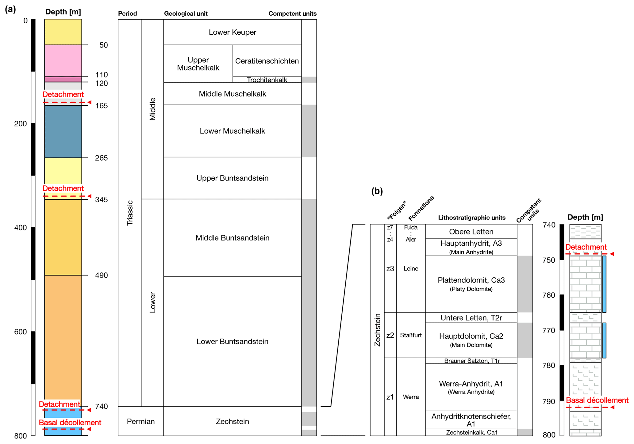
Figure 2(a) Stratigraphic column of Zechstein and younger units in the study area. Major detachment horizons and the basal décollement are indicated. Competent horizons are highlighted in grey. (b) Detailed stratigraphic column of the Zechstein Formation. Dolomite-bearing horizons, which produce the majority of the exotic fragments, are indicated in blue. The Hauptanhydrit and the Werra–Anhydrit form the most likely detachment horizons. Zechstein nomenclature after Paul et al. (2018). The Zechstein is underlain by Rotliegend of variable thickness or deformed older Paleozoic.
The Sontra Graben and several of the other graben systems (e.g., Creuzburg Graben, Eichenberg Fault Zone) exhibit enigmatic occurrences of Zechstein strata. The Zechstein rocks are found discontinuously as fault-bounded blocks or slivers and horses along the faults of the grabens. These slivers of Zechstein carbonates are structurally elevated relative to both the downfaulted interior and the footwall blocks that define the regional level. In the Sontra Graben they are some tens of meters to several hundred meters long along the faults and range in width from meters to a few tens of meters perpendicular to them. Internally, the slivers appear almost undeformed. However, in most cases the bedding is moderately to steeply dipping and strikes approximately fault-parallel.
It was previously suggested that the emplacement of the uplifted Zechstein blocks was due to salt diapirism (Lachmann, 1917) or intrusion of salt and other evaporites into the fault zone (Möbus, 2007). However, the absence of evaporites within these slivers and their dominant occurrence in areas of primarily low salt thicknesses challenge this concept. In this paper, we explore the hypothesis that the “exotic” Zechstein slivers were emplaced as a result of inversion tectonics involving bedding-parallel detachments in two evaporitic Zechstein horizons during both extension and contraction.
2.1 Data sources
Data were compiled from our own field observations and detailed analysis of the official geological maps of the area (Beyrich and Moesta, 1872; Moesta, 1876; Motzka-Noering et al., 1987), maps from published thesis papers of the 1920s and 1930s (Schröder, 1925; Bosse, 1934), and unpublished maps created during two diploma mapping projects at the University of Jena (Jähne, 2004; Brandstetter, 2006). Dip and strike data were also gathered from numerous unpublished reports written by students in the beginner-level mapping courses in the years 2014 and 2015 at the University of Göttingen. To complete the existing data, we mapped the exact position and extent of all Zechstein slivers and took dip readings where possible.
In recent years the area around the Sontra Graben was surveyed for the construction of a motorway, which is now underway. In the course of this survey, numerous shallow wells were drilled. We used information from two such wells to constrain the architecture of one fault hosting Zechstein slivers. Topography data for the cross sections and the geological map were obtained from the topographic map of Hessen (1 : 25 000) and from a digital elevation model (DEM) kindly provided by the Hessian Agency for Nature Conservation, Environment and Geology (HLNUG). Stratigraphic data (Fig. 2) were taken from Motzka-Noering et al. (1987), which also contains a compilation of various well and outcrop data.
2.2 Workflow
The collected map data were digitized and georeferenced using QGIS (QGIS Development Team, 2015). All geological mapping was done using the app FieldMove (© Petroleum Experts) on an Apple iPad Air 2. Data from the app were fed into QGIS via the .csv import function. Subsequently, a new internally consistent geological map was constructed (Fig. 3). The resulting map and dip data then served as the basis for modeling and cross section construction using the module 2DMove from the Move Suite (© Petroleum Experts). All data were transferred from QGIS into 2DMove via the shapefile (*.shp) or ASCII (*.txt) import functions.

Figure 3Geological map of the study area. Lines marked A–A′ and B–B′ indicate the position of the balanced cross sections in Fig. 6. Roman letters define sections of the graben between the dashed lines, which are referred to and further discussed in the text. Topography based on DEM data provided by the Geological Survey of Hessen (Hessisches Landesamt für Naturschutz, Umwelt und Geologie, Wiesbaden).
2.3 Cross section construction and modeling
2.3.1 Digital forward structural model
The forward model was constructed in 2DMove (© Petroleum Experts) to test the viability of inversion-related emplacement of the Zechstein slivers. We constructed an undeformed layer cake model with horizontal bedding using the average stratigraphic thicknesses of the study area. For simplicity, the model contains only one fault that represents the main southwestern boundary fault of the Sontra Graben, similar to the situation in the Mühlberg section. Using the 2D Move-on-Fault tool with the simple shear algorithm and a 60∘ shear angle, we simulated normal fault displacement followed by reverse motion, adjusting the fault geometry and displacement magnitudes until producing a Zechstein sliver wedged between Muschelkalk strata of the hanging wall and footwall, which display a small remaining normal offset in the final stage. Finally, the 2D unfolding tool with the simple shear algorithm and a 60∘ shear angle was used to create folding of the section at a larger wavelength. This step was necessary to produce the northeast dip of the footwall, which otherwise remains horizontal by default.
2.3.2 Constructing the balanced geological cross sections from map data
Two sections were constructed and balanced using 2DMove (© Petroleum Experts). Section A coincides with the large outcrop shown in Fig. 4, and section B lies very close to well 1 (Fig. 3). From the dip data, an orientation analysis was conducted to determine the optimal orientation for the cross sections. The calculated fold axis trends WNW–ESE, indicating a shortening direction consistent with the regional NNE–SSW extension and contraction directions deduced from the analysis of small-scale fault populations (Navabpour et al., 2017). Hence, approximately plain-strain deformation conditions for the profiles can be assumed for both the extensional and the contractional phase. All geological boundaries were derived from the newly compiled geological map (Fig. 3). The 2D unfolding tool with a flexural slip algorithm was used to flatten the folds. This algorithm conserves bed lengths when applied to a stratigraphy of uniform thicknesses while also allowing for the retrodeformation of faults and the topographic surface. The fault geometries were corrected through trial-and-error-cycles to reduce gaps or overlaps to a minimum. Both sections were constructed with similar structural geometries to ensure consistency and avoid the need to invoke abrupt structural changes between them.
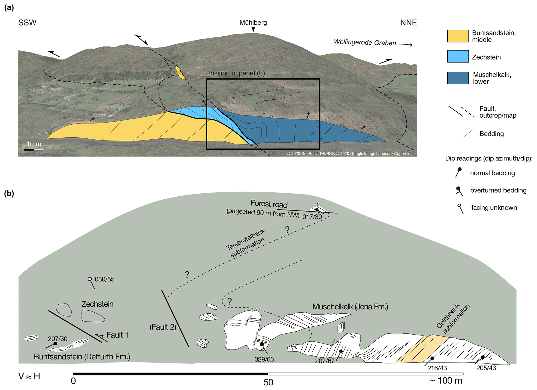
Figure 4(a) Outcrop along the train tracks west of Sontra (Schröder, 1925) shown as an overlay on a GoogleEarth image with fault traces extrapolated according to our own field data. (Image position 51∘4′57.35′′ N, 9∘56′24.49′′ E, with a view towards NNW; © GeoBasis-DE/BKG 2020, © Google Image Landsat/Copernicus 2020). One of the exotic Zechstein slivers, with approximately fault-parallel bedding, is thrust onto the middle Buntsandstein of the graben shoulder. The lower Muschelkalk overlying the sliver in the NNE is the partly overturned limb of a contractional anticline. (b) The same outcrop in the year 2000, drawn after field book sketches. Key observations by Schröder (1925) could still be confirmed.
3.1 Structure and segmentation of the Sontra Graben
The NW–SE-trending Sontra Graben extends for a length of 35 km between the N-trending Altmorschen–Lichtenau Graben in the west and the northwestern tip of the Thuringian Forest, a fault-bounded basement anticline in the east (Fig. 1). On both ends the Sontra Graben is reduced to a single fault before linking up with the other structures. Near its center, the Wellingerode Graben branches off from the Sontra Graben and runs first north-northeastward and then in a more northeasterly direction to meet the NW–SE-trending Netra Graben.
The main part of the Sontra Graben within the study area is subdivided into five segments for the purpose of this paper (Fig. 3), primarily based on the configuration of the Zechstein slivers but also largely coincident with other structural features. In the very northwest (segment I) the graben has a width of approximately 500 m. It is confined between the southwestern and northeastern boundary faults, both with a throw of 150 to 180 m when the Zechstein slivers are not considered. The southwestern fault has two strands with a narrow band of Muschelkalk strata between them. Zechstein slivers occur on both strands and are comparatively small (from 1000 to 16 000 m2; see Table 1 for details of these and the other Zechstein slivers). A second northeastern band of Muschelkalk appears in the easternmost part of segment I, overlapping the southwestern one over a few hundred meters. Another Zechstein sliver is present on the fault bounding this Muschelkalk band in the southwest. This fault takes the position of a central main fault.
Table 1Statistical compilation of the Zechstein slivers. The values for vertical offset are calculated based on thicknesses given by Motzka-Noering et al. (1987).

NA – not available.
Further to the southeast, segment II comprises a short stretch of graben near the village of Stadthosbach, where it becomes quite narrow (250 m). Only the northeastern band of Muschelkalk strata continues from segment I, confined between the northeastern boundary fault and the central fault, which marks the southwestern boundary and has small-sized Zechstein slivers along it. The net throw across the southwestern fault amounts to no more than 80 m.
In segment III the Sontra Graben widens again to as much as 1.2 km. A more complete succession of Muschelkalk Group strata reappears in the footwall of the central fault. The middle and upper Muschelkalk outcrop reveals an incompletely preserved, southeast-trending axial syncline, which in certain parts is well-silhouetted by the Trochitenkalk Formation of the upper Muschelkalk. The outcrop of discontinuous lower Muschelkalk blocks surrounded by upper Buntsandstein along the northeastern border becomes very broad in this part of the graben, probably due to fault repetition. The axial syncline of the Sontra Graben in this segment interferes with a similar but NNE-trending syncline belonging to the Wellingerode Graben. West of the Mühlberg hill, a fold interference pattern formed by superposition of the NW- and NNE-trending synclines produces a structural basin where strata of the Keuper Group are preserved. No Zechstein slivers are exposed in this part of the graben.
East of the intersection with the Wellingerode Graben, segment IV comprises the largest Zechstein slivers that appear exclusively along the southwestern border fault and terminate just west of the river Sontra. The graben again becomes very narrow (110 m) where the river transects it. The western end of the Zechstein sliver is exposed in the railroad cut along the foot of the Mühlberg hill, which was described by Schröder (1925) and has provided the best exposure so far of the Sontra Graben and one of the Zechstein slivers. Despite a much-deteriorated state of the outcrop today (Fig. 4), it still provides insight into fault geometries of the graben and the way the Zechstein slivers are juxtaposed with the shoulder of the graben and its interior. The downward-narrowing Zechstein sliver is bounded on its southwestern side by a low-angle northeast-dipping thrust fault emplacing it onto middle Buntsandstein. On its northeastern side the sliver is bounded by a northeast-dipping normal fault juxtaposing it against lower Muschelkalk, which is internally folded. Further uphill, a second small exotic sliver of middle Buntsandstein occurs between the Zechstein and the Muschelkalk. East of the river Sontra, a northeastern swath of segment IV exhibits oblong tilted blocks of lower Muschelkalk surrounded by upper Buntsandstein shale. This structure contrasts with open folding in a southwestern swath where the axial syncline reappears and becomes quite prominent.
In segment V, the graben widens to more than 2 km and also changes direction slightly to a more southwesterly trend, skirting the southern edge of the Ringgau, a topographically elevated panel of flat-lying Muschelkalk strata between the Sontra Graben and the Netra Graben. While the southwestern half of the graben is dominated by the widening and deepening axial syncline that preserves Keuper strata in its core, its northwestern half is occupied by a zone of fault-bounded and tilted blocks of lower Muschelkalk surrounded by upper Buntsandstein, similar to the structure of segment II and the western part of segment IV. Small Zechstein slivers occur only on the boundary fault of the graben in segment V but are restricted to its northwestern part (Fig. 3).
The Zechstein slivers vary greatly in size and shape (Fig. 5). A general trend towards larger, more continuous slivers can be observed from the northwest to the southeast, i.e., from segment I to V (Table 1, Fig. 3). The lower Muschelkalk appears most commonly as a bordering unit on the northeastern side of the slivers, while in the southwest the slivers are generally bordered by the upper Buntsandstein. Assigning a stratigraphical unit to the individual outcrops is sometimes difficult. Although most of the slivers actually produce conspicuous rocky outcrops and it is often possible to measure bedding dips, they generally consist of poorly bedded to massive, vuggy (cellular) dolomite of either the Hauptdolomit (z2, Staßfurt cycle) or Plattendolomit (z3, Leine cycle) carbonates (Fig. 2b). In addition, weathering has in some cases decomposed the rock to a powdery ash-like substance, rendering bedding unrecognizable.

Figure 5Photo panel of selected outcrops of Zechstein slivers along the Sontra Graben. The backpack is shown for scale. Approximate locations for each photo can be seen in Fig. 3.
3.2 Mechanical stratigraphy
This section focuses on the Zechstein stratigraphy, which is of prime importance for our structural model. The Zechstein transgression flooded the Southern Permian Basin from the central North Sea into western Poland and from the southern margin of the Baltic shield in the north to the Rhenish massif and the Bohemian massif in the south (Ziegler, 1990). The Zechstein sediments were deposited in seven recurring cycles (Richter-Bernburg, 1953). These cycles are recorded in seven “Folgen” z1 to z7 (the German term is used for these units by the German Stratigraphic Commission) or correlative formations (Paul et al., 2018, see Fig. 2). The most complete formations comprise clastic sediments at the base overlain by carbonates, sulfates, halites, and potash and magnesium salts. The full seven formations are restricted to the central parts of the basin (Becker and Bechstädt, 2006). Situated on the southern margin of the Southern Permian Basin, the study area mainly comprises the first three Zechstein formations: the Werra, Staßfurt, and Leine formations (or z1 to z3 Folgen). It contains the four subsequent formations only in a shaly marginal facies. The basin margin character of the study area resulted in original Zechstein thicknesses in parts as low as 60 m. From a mechanical viewpoint, the Zechstein constitutes a relatively thin but very heterogeneous succession of alternating competent and incompetent packages. The strongest units are the carbonates of the Werra and Staßfurt formations, traditionally termed the Hauptdolomit (Main Dolomite, Ca2) and Plattendolomit (Platy Dolomite, Ca3). The Zechstein slivers in the Sontra Graben typically consist of poorly bedded to massive vuggy (cellular) dolomite, a facies that occurs in both the Ca2 and Ca3 carbonates.
Prominent weak layers and potential detachment horizons are evaporites and shales. The Ca2 carbonate is underlain by thick sulfate and shale of the Werra Formation, termed the Werra–Anhydrit (A1) and Braunroter Salzton (brownish red salty clay, T1r). T1r consists of up to 4 m thick, greyish green, thin-layered shales originally interspersed with thin layers of halite. There is no indication of primary massive rock salt in the Werra Formation of the study area. Above the Ca2 carbonate and separating it from Ca3 there is another shale horizon. Again, there is no indication of salt in the Staßfurt Formation in this part of the basin. The Ca3 carbonate is either overlain by anhydrite (A3) or grey clayey carbonates (Ca3T). Near the town of Sontra, the Hauptanhydrit (A3) level is exposed as relatively homogeneous gypsites with thin (1 cm) layers of brownish dolomite. Traditionally, the term Obere Letten (upper clays) was used as a collective term for claystones, siltstones, and sandstones of small thickness overlying Ca3 or A3, which are now attributed to the Leine, Aller, Ohre, Friesland, and Fulda formations (or z3 to z7 Folgen).
The z3 to z7 shales grade upwards into the Triassic Buntsandstein via a succession of siltstones. The Triassic succession comprises three competent units: the thick and mostly sandy lower and middle Buntsandstein, the rather homogenous, thin-bedded limestone sequence of the lower Muschelkalk, and the thin but mechanically strong lower part of the upper Muschelkalk (Trochitenkalk Fm.) consisting of thick-bedded grainstones and rudstones. Potential detachment horizons between these units are formed by the evaporitic and shaly upper Buntsandstein and the evaporitic and marly middle Muschelkalk. These detachments are important for second-order features such as the Zechstein slivers wedged into middle Muschelkalk. The higher part of the upper Muschelkalk and Keuper together represent an incompetent stratal package at the top of the preserved column.
3.3 Forward model
The forward structural model served to test our working hypothesis developed from field observations that the present-day small offset of the Sontra Graben's main southwestern fault(s) represents the sum of a much larger normal offset and reverse reactivation of similar magnitude. The model was designed to simulate the main features of the Mühlberg section, which, as described above, is comparatively well-constrained and structurally simple except for the exotic Zechstein sliver. One aim was to estimate the minimum normal displacement required to attain the starting condition for the formation of the Zechstein slivers, i.e., Muschelkalk of the hanging wall juxtaposed against Zechstein of the footwall. The model was particularly useful in exploring the influence of detachments in the Zechstein units and provided a template for the construction of the two balanced cross sections. The fault of the final model has an overall listric geometry with a dip angle of 60∘ at the surface that becomes a bedding-parallel detachment at a depth of 800 m within the Werra–Anhydrit (Fig. 6a). The listric geometry is broken by three flats or short detachments sitting in the middle Muschelkalk: the upper Buntsandstein and the Hauptanhydrit (A3) of the Zechstein. An extension of approximately 1.2 km is sufficient to bring the lower Muschelkalk of the hanging wall to Zechstein depth with the listric fault geometry described (Fig. 6b). A flat in the Hauptanhydrit (A3) creates a step in the fault geometry, which upon inversion promotes the formation of a shortcut thrust. For the inversion phase, such a shortcut thrust was introduced at the earliest stage (Fig. 6c), creating a Zechstein horse delimited by the original normal fault as a roof thrust (or non-reactivated fault) and the newly created shortcut thrust as a sole thrust. A backthrust was also modeled that emplaces the Zechstein horse onto the underlying lower Muschelkalk of the hanging wall. This was included in the model because data from a well just 20 m to the northwest of section B indicate that Zechstein is thrust on top of the lower Muschelkalk of the hanging wall at a shallow depth of approximately 30 m. Shortening of approximately 1000 m sufficed to elevate the newly created Zechstein sliver to a regional stratigraphic level within the upper Buntsandstein (Fig. 6d), a level where the slivers are commonly found. Finally, the 2D unfolding tool with the simple shear algorithm and a 60∘ shear angle was used to model wholesale folding of the half-graben at a larger wavelength of about 1.5 km (Fig. 6e). This feature is required to replicate the dip values observed in the field, especially the northeast dip of the main fault's footwall.

Figure 6Forward model of the formation of the Sontra Graben. Stratigraphic thicknesses from Motzka-Noering et al. (1987).
Flats in the middle Muschelkalk and the upper Buntsandstein were incorporated to acknowledge the role of these units as detachment horizons. The kinked fault geometry causes strong distortion of the modeled hanging wall during inversion (Fig. 6d) and would also do so during extension. In nature, the arising stress concentration around the kinks would probably promote straightening of the fault by excision of slivers. Similarly, the sudden drop of Zechstein thickness in the hanging wall where the future exotic sliver was located induces a narrow zone of shearing (Fig. 6b) that would probably correspond to an antithetic normal fault in nature.
3.4 Balanced cross sections
Cross section A (Mühlberg, Fig. 7a) and cross section B (Weißenborn, Fig. 7b) were constructed using the same basic geometry. The main northeast-dipping normal fault has a listric geometry down to the depth of the secondary detachment above the Ca3 carbonates, which it follows for a short distance before stepping down to the main detachment in the Werra–Anhydrit at a depth of approximately 300 m below the present surface. The southwest dip of the hanging wall is caused by rollover on the listric fault. The northeast dip of the footwall cannot be an effect of the fault but requires additional open folding of the entire structure, including the basement. As stratigraphic horizons in the immediate footwall of the main fault lie lower than their hanging wall counterparts, short southwest-dipping segments of the footwall are necessary in both sections to bring the Zechstein detachment to the regional elevation of the Werra–Anhydrit in the northeast.
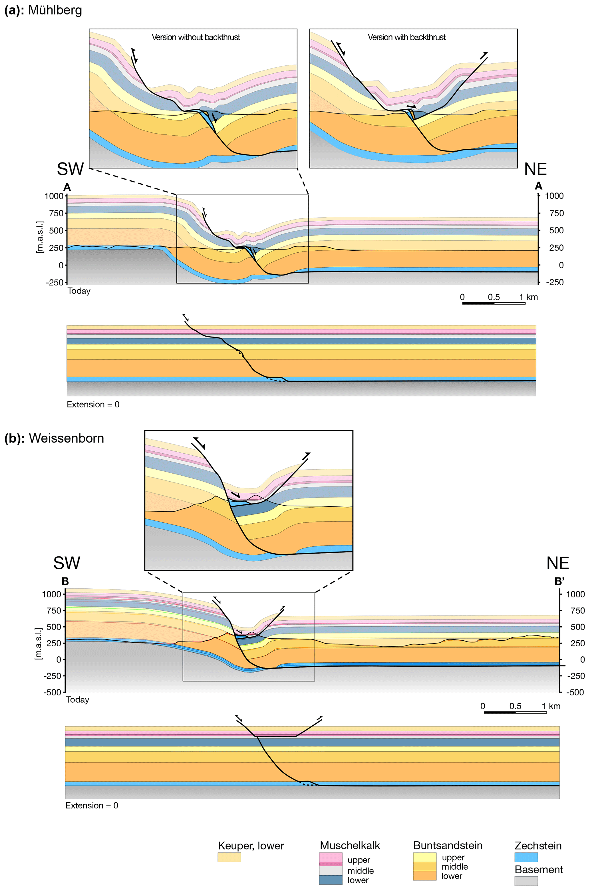
Figure 7Balanced cross sections of the Sontra Graben. The fault geometry was verified through the forward model in Fig. 6. For section traces, see Fig. 3.
The structure of the Zechstein sliver is better constrained in cross section B where the well has demonstrated it is emplaced on the Muschelkalk of the hanging wall. This suggests the sliver overlies a backthrust that is modeled as an emergent fault. Alternatively, the sliver could be wedged beneath the middle Muschelkalk under a southwest-directed passive roof thrust. Erosion of potential hanging wall cutoffs and poor exposure of the middle Muschelkalk do not allow us to prove or disprove the existence of an emergent backthrust.
For section A (Fig. 7a) we have modeled two scenarios: one includes a backthrust corresponding to the one in section B, the other one has no backthrust. Two fault-bounded slivers of Zechstein and middle Buntsandstein appear parallel to the master fault. In the first scenario they are cut off at shallow depth by the backthrust. The space occupied by the slivers tends to make bed lengths of the base and top lower Muschelkalk horizons too short, a problem that is exacerbated by the deeper-reaching slivers of the second scenario. This version therefore includes some distributed shortening and thickening of the upper Buntsandstein and lower Muschelkalk, consistent with field observations. Longer-wavelength basement-involved folding in the final stage of inversion steepens the angle of the main normal fault (Fig. 6e).
At the location (Fig. 3) of cross section B (Fig. 7b), the graben has a width of approximately 370 m and includes the largest of the Zechstein slivers. The boundary fault in the southwest dips at an angle of approximately 70∘ towards the northeast and flattens out to become a horizontal detachment at a depth of approximately 450 m. The center of the graben is occupied by an open syncline in middle to upper Muschelkalk. Its southwestern limb is interpreted here to be supported by the underthrust wedge-shaped Zechstein sliver, masking the southwest dip of deeper units caused by rollover on the boundary fault. The backthrust is modeled with a similar geometry as in section A parallel to bedding on the northeast limb of the synclinal graben center. Different from cross section A, it detaches in the middle Muschelkalk instead of the upper Buntsandstein. Basement-involved folding is also required in cross section B to explain the northeast dip of the southwestern shoulder and the Zechstein depressed to slightly beneath its regional elevation below the graben.
3.5 Additional cross sections
We have drawn a series of conceptual cross sections extending basic features of our interpretation to the remaining Sontra Graben (Fig. 8). Common features along the inverted (half-)graben include a southwestern shoulder dipping towards the graben, a northeast-dipping listric master fault, one or several synthetic secondary faults, and a subhorizontal northeastern shoulder. An antithetic northeastern border fault of substantial throw is only present in the northwestern part of the Sontra Graben between cross sections a–a′ and c–c′. There, the graben interior comprises two swaths of upper Buntsandstein and lower Muschelkalk, both of overall synclinal geometry and separated by a major longitudinal fault. Both this central fault and the antithetic northern border fault die out towards cross section c–c′ where the two Muschelkalk swaths coalesce to eventually be crossed by the NNE-trending syncline of the Wellingerode Graben. The exotic Zechstein occurrences are bound to the southeastern border fault and the central fault. The southeastern part of the graben has a different structure. Depending on the structural level exposed it exhibits a series of oblong blocks of lower Muschelkalk dipping into faults and bounding them on their southwestern sides or an overlying syncline comprising middle Muschelkalk to Keuper strata. All Zechstein occurrences are aligned along the southeastern border fault. Our inversion tectonic model explains the narrow Zechstein slivers extending along faults and dipping parallel to them, but it does not predict the structurally elevated yet gently dipping Zechstein strata occupying larger areas as observed or interpreted in cross sections a–a′ and d-d′. These are interpreted as overlying north-directed backthrusts as proven for section B (Weißenborn).

Figure 8Sections a–d: conceptual cross sections of the Sontra Graben northwest and southeast of the balanced cross sections in Fig. 7. Basic features of our forward model and balanced cross sections were adopted to interpret surface observations in these sections. Section e: longitudinal cross section illustrating the effect of varying erosion levels on the appearance of the graben. Only the hanging wall of the boundary fault to the depth of the upper Buntsandstein is shown. Notice the axial syncline of the Wellingerode half-graben, which in this location forms the fold interference pattern with the axial syncline of the Sontra Graben (Fig. 3). Section traces are shown in Fig. 3.
In cross section a–a′, the hanging wall of the central fault, with its widely exposed middle Buntsandstein, lies too high to be explained by thin-skinned deformation. We have therefore included a southwest-directed basement thrust, which represents a more pronounced expression of the basement-involved deformation that produced folding of the basal detachment in the other sections.
4.1 Overall structure of the Sontra Graben and fault geometries
The Sontra Graben exhibits marked variations in structural style both along and across its strike. The along-strike variations were already described in Sect. 3.1. The most conspicuous across-strike change is from open folding in the southwest, next to the main fault, to block faulting and tilting in the northeast. This difference is best expressed in segments IV and V and to a lesser degree in segment III. We interpret it to reflect a vertical change in structural style revealed by a varying depth of erosion, which in some cases is accentuated by changes in the structural level across transverse faults (see longitudinal cross section, Fig. 8e). Open folding affects middle Muschelkalk to Keuper strata, whereas the tilted blocks consist of lower Muschelkalk surrounded by upper Buntsandstein. We interpret this vertical contrast as an effect of detachment in the predominantly marly and evaporite-bearing middle Muschelkalk (Fig. 9). This detachment must have already been active during the extension phase. It was again instrumental for the emplacement of the Zechstein sliver along a backthrust in the Weißenborn section. The existence of normal fault flats in the middle Muschelkalk was proven by tunneling across the border fault of the Leinetal Graben, circa 40 km north of the study area (Arp et al., 2011). There, a fault segment with a flat in middle Muschelkalk overlying another one in upper Buntsandstein was exposed. Occurrences of middle and upper Muschelkalk on Zechstein near the northern end of the Altmorschen–Lichtenau Graben (Fig. 1b) are also best explained as erosional remnants of a normal-fault hanging wall floored by a flat in the middle Muschelkalk (Möbus, 2007).
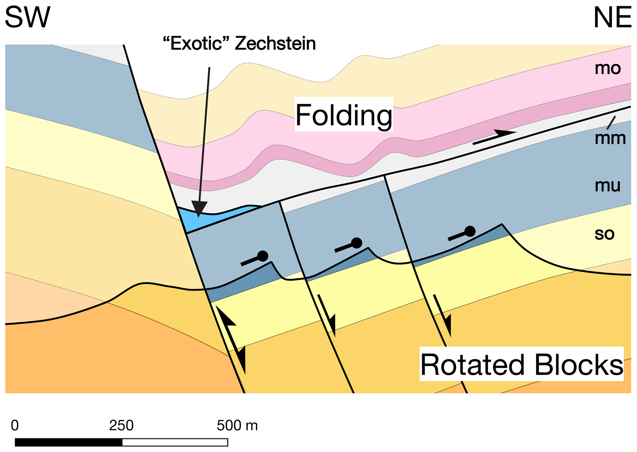
Figure 9Schematic model of the relation between a lower structural level with rotated blocks and an upper structural level dominated by folding as a result of a detachment within the middle Muschelkalk. Faults delimiting the rotated blocks within the lower floor peter out into the middle Muschelkalk or merge into the detachment. Through varying degrees of erosion the different styles become visible or predominant in the different segments.
Flats at different Zechstein levels play a key role in the formation and shape of the Zechstein slivers. A perfectly listric geometry of the main normal fault where it curves smoothly into the basal detachment would discourage the formation of slivers. A more suitable geometry is created if the fault flattens into a higher detachment for some distance and then steps down via a relatively steep ramp to the basal one. In this configuration, a footwall shortcut thrust can propagate along the basal detachment and then step up over a low-angle ramp to merge with the normal fault, smoothing its trajectory and isolating the sliver (Fig. 10a). The along-strike and across-strike extents of the flat control the size and geometry of the observed Zechstein slivers, whereas height above the basal detachment controls their thickness. Given that the vertical distance between the top of the Hauptanhydrit and the top of the Werra–Anhydrit around the Sontra Graben is only between 60 and 80 m, the total thickness of a sliver cannot exceed this value.
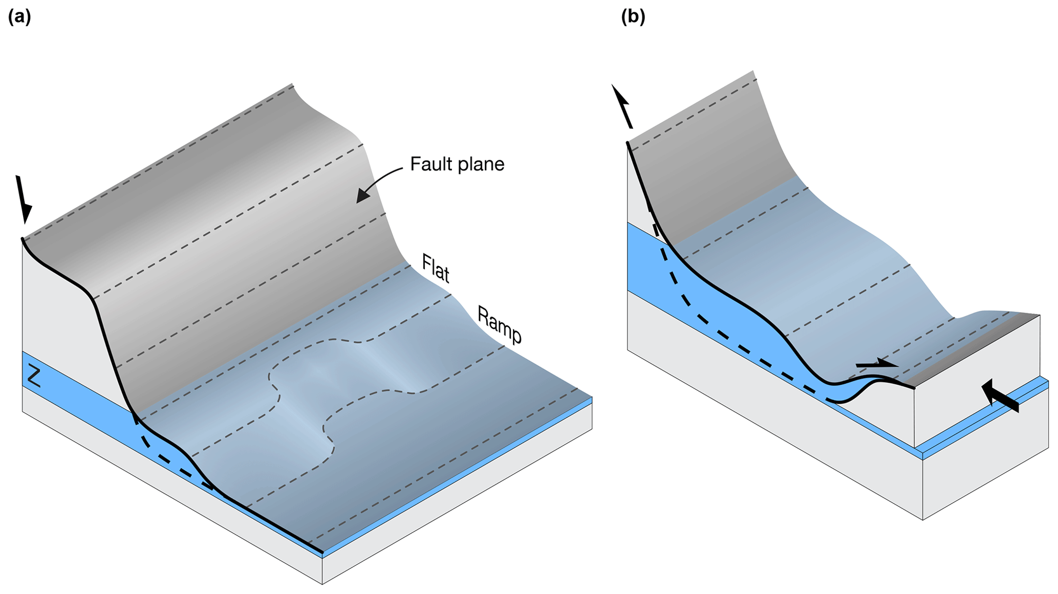
Figure 10Schematic model of the formation of a horse and the backthrust onto the hanging wall during inversion. The slivers are formed as horses with the newly formed shortcut thrust as a floor thrust and the original normal fault as a roof thrust. Panel (a) shows the geometry of the original normal fault, with areas showing more or less pronounced development of flats. Areas with more pronounced flats produce the aforementioned exotic slivers. Areas with less pronounced flats produce smaller or no slivers. Panel (b) shows the newly formed sliver being backthrust onto the hanging wall during the inversion phase.
Backthrusts are well-documented features of inverted grabens (Hayward and Graham, 2015). The insertion of Zechstein strata into evaporite-bearing Triassic units during inversion is reminiscent of “salt wedges” (Baldschuhn et al., 1998; Stewart, 2007) but differs in two aspects: the slivers are always located in hanging walls and do not involve thick halite. Backthrusting of Zechstein slivers and wedging into the hanging wall (Figs. 6, 7, 8) are likely to have occurred at an early stage of the inversion phase when normal fault displacement was at a maximum, with lower Muschelkalk of the hanging wall having passed the future sliver and middle Muschelkalk overlying it. Upon inversion, the leading edge of the lower Muschelkalk must have underthrust the Zechstein sliver for some distance before it became detached from the footwall (Fig. 10b).
The comparatively well-exposed Mühlberg Zechstein sliver (Fig. 4) presents two secondary structural features that are not predicted by our model: (1) the sliver is underlain by a low-angle thrust fault that truncates its bedding and cuts stratigraphically downward unless the entire sliver is overturned, and (2) it is overlain by folded Muschelkalk whose overturned bedding abuts the roof fault of the sliver. Figure 11 shows possible explanations for these phenomena. The peculiar Muschelkalk–Zechstein relation is probably due to a horse cut from the hanging wall and left behind at depth. Southwest-verging folds in the Muschelkalk must predate the excision of this horse and suggest buttressing by the steeply dipping normal fault, the trailing edge of the future sliver, or both. Short flats of the main normal fault would promote the creation of horses via fault straightening (Fig. 11a). The bedding of the sliver truncated by the floor thrust could also be due to this mechanism. Alternatively, it could represent the hanging wall of an antithetic normal fault and would then indicate the sliver's trailing edge. However, a more straightforward solution may be as shown in Fig. 11b and c: the low-angle thrust fault here is not the original floor thrust of the sliver but a later one that has cut across it from the roof fault and displaced its upper part along an upper Buntsandstein detachment of the footwall. This geometry also eliminates the need for mechanically implausible motion of the hanging wall rocks through the sharp transition from the low-angle fault to the steeply dipping segment juxtaposing the Zechstein sliver with the Muschelkalk of the footwall.
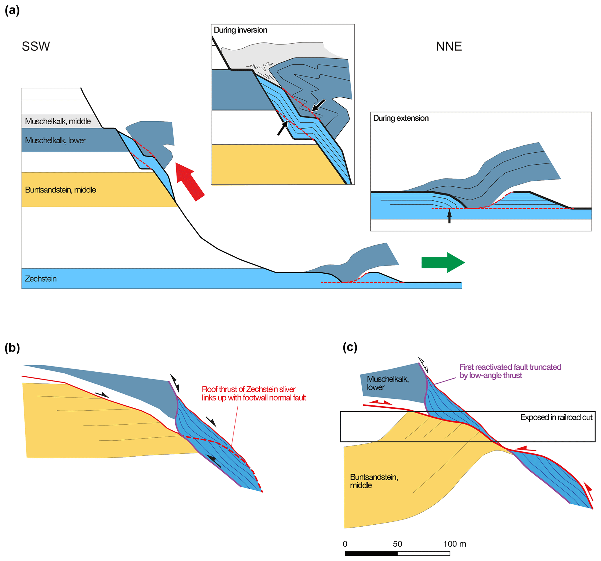
Figure 11Scenarios for the origin of second-order structural features within and above the Mühlberg Zechstein sliver (Figs. 4 and 7). (a) The floor thrust cutting down-section across bedding in the sliver and the roof fault truncating overturned Muschelkalk strata could be due to straightening of kinked fault segments during inversion (new fault trajectories shown as dashed red lines with fault–bedding relations highlighted by arrows). The truncation of bedding in the sliver by the floor thrust could also be inherited from an antithetic normal fault of the extensional phase. (b, c) Alternative model for the floor thrust–bedding relation. After emplacement of the sliver to its present-day structural elevation (b), the roof thrust cuts across it to a detachment in the upper Buntsandstein of the footwall, displacing the upper exposed half of the sliver to the southwest on a low-angle fault (c). We consider a combination of (a) for the truncated Muschelkalk with (b) and (c) for the floor thrust most likely.
4.2 The Zechstein as a décollement horizon
The presence of the Zechstein slivers is strong evidence for bedding-parallel flats or detachments at different Zechstein levels in the normal faults that formed the Sontra Graben. Had the initial normal fault of the graben cut straight down into the basement, inversion could not have created isolated horses of Zechstein whose bounding faults follow bedding for tens to hundreds of meters. The Zechstein succession, with its multiple evaporite layers, is prone to forming detachment horizons (Fig. 2b). Evaporites often play a key role in decoupling the sedimentary cover from the basement, such as in the extensional fault systems at the passive margins of the Gulf of Mexico and Brazil (Duval et al., 1992; Demercian et al., 1993; Adam et al., 2012), but also in intracontinental basins such as the North German Basin (e.g., Mazur et al., 2005), where the Zechstein evaporites are much thicker than in the Sontra region. Stewart (2007, his Fig. 25) proposed a “structural style matrix” for the North Sea. The Sontra Graben, owing to its position on the anhydrite-dominated basin margin, is not a typical salt-related inversion structure as described there. It falls between the “one detachment” and “thick detachment plus secondary detachments” categories of salt tectonic influence defined by Stewart (2007). Salt (or other evaporites) is present but not thick enough to form large accumulations, and multiple detachment horizons are required to from the slivers.
In the absence of seismic data, we can only speculate on whether the main Zechstein detachment was of regional extent and where it linked up with basement faults. The long-wavelength folding of the graben (Figs. 6, 7) created structural relief that is much higher than the thickness of the Zechstein and therefore must involve the basement. The monocline south of the Sontra Graben belongs to the broad, gentle Richelsdorf basement anticline (Fig. 1c). Conceivably, the shortening (and possibly also the extension) expressed in the Sontra Graben was accommodated there at basement level. This solution is tentatively shown in Fig. 1c and resembles seismically imaged structures from the North Sea (Sole Pit High and peripheral grabens; Stewart and Coward, 1995) and the inverted Mid-Polish Trough (axial part of the Pomerian segment with peripheral fold–thrust structures; Krzywiec, 2002, 2006).
4.3 Timing, kinematics, and magnitude of extension and inversion
Since a significant portion of the Sontra Graben including syn-rift and post-rift sediments has been eroded and only its roots remain, it is not possible to directly constrain the ages of extension and inversion. Lower Keuper strata in fault contact with older Triassic units (Buntsandstein) require all deformation to have occurred after the deposition of the lower Keuper. Regional correlation with the better-preserved Lower Saxony Basin suggests that extension started in Keuper time but peaked in the Late Jurassic to Early Cretaceous, whereas inversion is of Late Cretaceous age (e.g., Kockel, 2003; Voigt et al., 2008). The inversion phase is also well-constrained by exhumation and cooling reflected in thermochronological ages (von Eynatten et al., 2008, 2019, 2020).
The relative timing for the formation of the NW-trending Sontra and Netra grabens versus the NE-trending Wellingerode Graben poses another difficulty. The Wellingerode Graben has a marked effect on the interior of the Sontra Graben (Figs. 3, 8e) and the Netra Graben, but it appears to terminate at their southwestern and northeastern border faults, respectively. Similar to joint propagation (Engelder, 1985), this would imply that the Sontra Graben and Netra Graben already existed when the Wellingerode Graben formed. Nevertheless, the Wellingerode Graben does not appear as a typical hard link between two overlapping graben segments. The Sontra Graben extends far beyond its intersection with the Wellingerode Graben on either side. The Netra Graben terminates in the west on a NE-striking structure that lies on trend with the Wellingerode Graben and connects to the Unterwerra Basement High (UWBH in Fig. 1b), suggesting that a precursor structure of the Wellingerode Graben existed when the Netra Graben propagated westward. Both the NW- and NE-striking fault sets include very long structures (Fig. 1b), arguing against one of them being a secondary effect of the other.
The kinematics of Late Cretaceous inversion in central Europe have often been interpreted as transpressive (Betz et al., 1987; Ziegler, 1987; Drozdzewski, 1988; de Jager, 2007; Drozdzewski and Dölling, 2018) or even as being predominantly caused by strike-slip motion on the northwest-striking faults with uplift focused on restraining bends (Wrede, 1988). Other authors proposed predominantly dip-slip contraction (Martini, 1937; Seidel, 1938; Rauche and Franzke, 1990; Kockel, 2003; Kley and Voigt, 2008); see Wrede (2008, 2009) and Voigt et al. (2009) for a focused version of that debate. To our knowledge, conclusive evidence from kinematic indicators has been presented for dip-slip motion (Franzke et al., 2007; Kley and Voigt, 2008; Sippel et al., 2009; Kley, 2013; Navabpour et al., 2017) but not for transpression.
The inversion model requires substantially larger fault displacements in excess of 1000 m in extension and contraction than the small net normal displacement of the Sontra Graben's present configuration. West of section A (segments I and II) the occurrence of the Zechstein slivers along one main reverse-activated normal fault changes to a different pattern, with a double row of slivers along the two faults termed the central and master faults in Sect. 3.5. The westernmost Zechstein sliver in Fig. 3 is bound to yet another fault that appears southwest of the master fault. These three faults are linked by left-stepping relays that approximately coincide with the locations of cross sections a–a′ and b–b′. We suggest they function as parts of a transfer structure and merge at depth into the same detachment (Fig. 12). Different from this schematic illustration the faults are probably also connected at the present erosion level because their displacements are too large to die out over short distances.
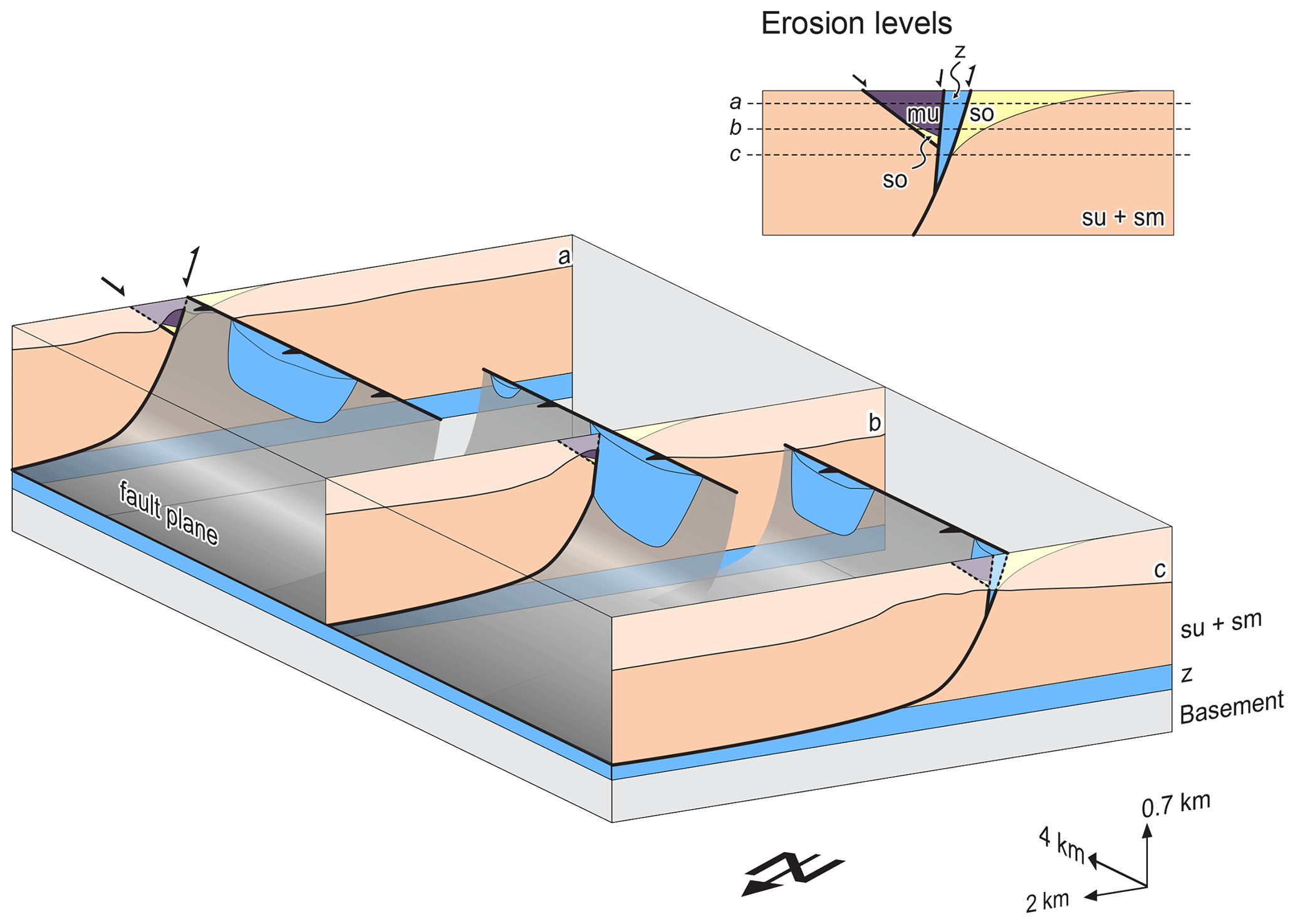
Figure 12Schematic model explaining the appearance of multiple rows of Zechstein slivers along imbricated faults as part of a transfer-type structure observed in the western part of the graben (section I, Fig. 4). Different erosion levels determine the width of the graben as it appears on the map.
Where the master fault and central fault overlap in the easternmost part of segment I, both carry Zechstein slivers (cross sections a–a′ and b–b′). This configuration can be interpreted in two ways: either they were both emplaced by reverse reactivation of the respective fault (a solution that appears more likely for section b–b′) or they are dismembered parts of an originally contiguous sliver. For instance, the northwestern sliver in section a–a′ could have been emplaced by the backthrust across the Muschelkalk syncline, which would represent a tectonic window. In either case, this part of the graben must have experienced the largest amounts of extension and shortening, either due to reverse reactivation of two faults instead of one or due to increased normal displacement along a detachment at the top of a wide Zechstein sliver. Extension and shortening would be almost twice that of sections A or B: around 2000 m. The width of the graben is therefore not an indicator of strain magnitude.
4.4 Distribution of exotic slivers
The question of why Zechstein slivers only occur on some grabens remains a key issue. We speculate that a specific paleogeographic configuration gave rise to this phenomenon. Notably, all exotic Zechstein slivers appear on two relatively discrete bands near the southern edge of the z1 basin (Fig. 13) and predominantly originate from its carbonate shelf, with the exception of localities 1 and 2, which are relatively small occurrences that originate from the sulfate slope. The area of the Sontra Graben is also situated just on the northeastern edge of the Schemmern Swell and close to the center of the Waldkappel Depression, two paleogeographic features of the Z1 basin (Kulick et al., 1984). We propose that the basin margin facies, with its alternation of strong carbonate layers and evaporites that are thick enough to act as detachments but too thin to form proper salt structures (pillows and diapirs), provided the most suitable mechanical stratigraphy for the formation of the slivers.
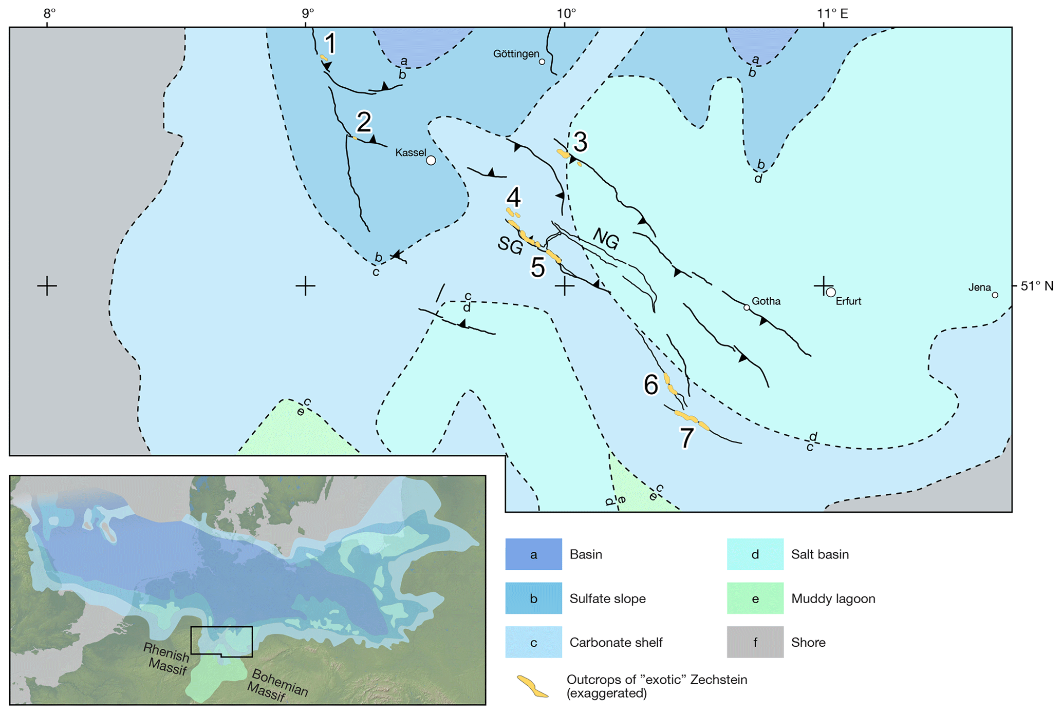
Figure 13Paleogeographic map of the first Zechstein cycle (Z1, Werra cycle). Outcrops of exotic Zechstein are shown in black for better visibility. Locality 5 is the subject of this study. Zechstein paleogeography from Kiersnowski et al. (1995). Digital elevation model made with GeoMapApp (http://www.geomapapp.org, last access: 11 March 2020); CC BY.
However, other factors must also play a role. The Netra Graben (Fig. 1) is in close proximity to the Sontra Graben and in the same basin realm but has no exotic slivers, Zechstein or otherwise. One possibility is that extension and fault displacement in the Netra Graben did not suffice to bring the lower Muschelkalk as far down as the Zechstein. As the Netra Graben is somewhat less eroded than the Sontra Graben with a higher proportion of preserved upper Muschelkalk and Keuper, Zechstein slivers could also be present at depth but not yet exposed.
The Sontra Graben is one of many NW-trending structures in the CEBS. It displays unambiguous signs of both extension and contraction (inversion). Its basic structure is asymmetric, with a northeast-dipping master fault bounding it in the southwest. A conjugate northeastern bounding fault is not continuously developed. Variations in structural style along the (half-)graben are due to a combination of different factors including left-stepping relays of the master fault and rapid changes in the level of exposure associated with topography and transverse faults. These changes reveal a middle Muschelkalk detachment separating a block faulting style beneath it from open folding above. The (half-)graben widens where extension was distributed onto a larger number of faults, while contraction was focused around the master fault. There seems to be no correlation between the width of the graben and bulk strain.
The Sontra Graben exhibits an unusually high number of “exotic” Zechstein slivers of varying size. The slivers are lenses of carbonates up to several hundred meters in length emplaced along the main graben faults to a structural position higher than either the graben interior or the shoulders. The geometry of the Zechstein slivers suggests that they formed during inversion via shortcut thrusts dissecting a stepped normal fault with ramps and flats. Backthrusts locally emplaced the slivers into incompetent units of the hanging wall. Geometrical forward modeling of the Zechstein slivers and cross section balancing suggest minimum values of approximately 1.2 km of horizontal extension and shortening for the extensional and contractional phase.
The occurrence and geometry of the Zechstein slivers in the Sontra Graben indicate thin-skinned tectonics with a basal décollement in the Werra–Anhydrit of the lowest Zechstein cycle and at least one additional higher Zechstein detachment. The corresponding mechanical stratigraphy reflects deposition on the basin margin with thin but strong carbonate levels and no thick halite. At sub-Zechstein level, shortening may have been accommodated on a basement thrust underlying the Richelsdorf Anticline to the south. This hypothetical thrust fault could have fed its displacement into the Zechstein décollement and caused the pronounced northeast dip of the southwestern graben shoulder.
MOVE is commercial software. It is a standard for structural modeling and kinematic restoration in the petroleum industry. Upon request it can be made available to academic institutions free of charge by the owner, PETEX.
The dip data used for the construction of the balanced cross sections are available in the Supplement.
The supplement related to this article is available online at: https://doi.org/10.5194/se-12-1005-2021-supplement.
JK conceptualized the study. JB performed the investigation including fieldwork, forward modeling, and cross section balancing, with some contribution by JK. JB and JK worked jointly on validation, visualization, and writing, including draft preparation, review, and editing.
The authors declare that they have no conflict of interest.
This article is part of the special issue “Inversion tectonics – 30 years later”. It is not associated with a conference.
We thank the Geological Survey of Hessen (Hessisches Landesamt für Naturschutz, Umwelt und Geologie, Wiesbaden) for kindly providing high-resolution DEM data in the framework of this project. We have benefited a great deal from the comments and suggestions by Stefan Back (RWTH Aachen), Andrzej Konon (Warsaw University), Alexander Malz (Landesamt für Geologie und Bergwesen, Sachsen-Anhalt), Stanislaw Mazur (Polish Academy of Sciences), and one anonymous reviewer that made us think and work harder. Many thanks to them all for patiently pointing out weaknesses in the first version of the paper. Finally, we would like to acknowledge the contributions over many years by students in mapping courses at the universities of Jena and Göttingen. We gratefully acknowledge support by the Open Access Publication Funds of the Göttingen University.
This paper was edited by Piotr Krzywiec and reviewed by Stefan Back, Stanislaw Mazur, Andrzej Konon, Alexander Malz, and one anonymous referee.
Adam, J., Ge, Z., and Sanchez, M.: Salt-structural styles and kinematic evolution of the Jequitinhonha deepwater fold belt, central Brazil passive margin, Mar. Petr. Geol., 37, 101–120, https://doi.org/10.1016/j.marpetgeo.2012.04.010, 2012.
Arp, G., Tanner, D., and Leiss, B.: Struktur der Leinetalgraben-Randstörung bei Reiffenhausen, in: Neue Untersuchungen zur Geologie der Leinetalgrabenstruktur, Universitätsverlag Göttingen, 17–21, 2011.
Baldschuhn, R., Frisch, U., and Kockel, F.: Der Salzkeil, ein strukturelles Requisit der saxonischen Tektonik, Z. Dtsch. Geol. Ges., 149, 59–69, 1998.
Becker, F. and Bechstädt, T.: Sequence stratigraphy of a carbonate-evaporite succession (Zechstein 1, Hessian Basin, Germany), Sedimentology, 53, 1083–1120, https://doi.org/10.1111/j.1365-3091.2006.00803.x, 2006.
Betz, D., Fohrer, F., Greiner, G., Plein, E., and Plein, G.: Evolution of the Lower Saxony Basin, Tectonophysics, 137, 127–170, 1987.
Beyrich, E. and Moesta, F.: Erläuterungen zur geologischen Specialkarte von Preussen und den Thüringischen Staaten, Blatt Sontra, 1872.
Bosse, H.: Tektonische Untersuchungen an niederhessischen Grabenzonen südlich des Unterwerrasattels, Abh. des Preuß. Geol. Landesamtes, Neue Folge, 1–37, 1934.
Brandstetter, A.: Der nordwestliche Sontra-Graben, Unpublished diploma mapping project report, University of Jena, 2006.
Brochwicz-Lewiński, W. and Poźaryski, W.: The mesozoic and tertiary evolution of the Polish Trough, Tectonophysics, 137, 1–4, https://doi.org/10.1016/0040-1951(87)90312-X, 1987.
de Jager, J.: Geological development, in: Geology of the Netherlands, Roy. Netherlands Acad. Arts Sci., Amsterdam, 5–26, 2007.
Demercian, S., Szatmari, P., and Cobbold, P. R.: Style and pattern of salt diapirs due to thin-skinned gravitational gliding, Campos and Santos basins, offshore Brazil, Tectonophysics, 228, 393–433, https://doi.org/10.1016/0040-1951(93)90351-J, 1993.
Drozdzewski, G.: Die Wurzel der Osning-Überschiebung und der Mechanismus herzynischer Inversionsstörungen in Mitteleuropa, Geol. Rundsch., 77, 127–141, https://doi.org/10.1007/BF01848680, 1988.
Drozdzewski, G. and Dölling, M.: Elemente der Osning-Störungszone (NW-Deutschland), Leitstrukturen einer Blattverschiebungszone, https://www.gd.nrw.de/pr_bs_scriptumonline.htm (last access: 25 March 2021), 2018.
Duval, B., Cramez, C., and Jackson, M. P. A.: Raft tectonics in the Kwanza Basin, Angola, Mar. Petr. Geol., 9, 389–404, https://doi.org/10.1016/0264-8172(92)90050-O, 1992.
Engelder, T.: Loading paths to joint propagation during a tectonic cycle: an example from the Appalachian Plateau, USA, J. Struct. Geol., 74, 459–476, 1985.
Franzke, H.-J., Müller, R., Voigt, T., and von Eynatten, H.: Paleo-Stress Paths in the Harz Mountains and surrounding areas (Germany) between the Triassic and the Upper Cretaceous Paläo-Stress Pfade im Harz und angrenzenden Gebieten (Deutschland) zwischen der Trias und der Oberkreide, Z. Dtsch. Ges. Geowiss., 35, 141–156, 2007.
Gebhardt, U., Lützner, H., Ehling, B. C., Schneider, J. W., Voigt, S., and Walter, H.: Comments on the Stratigraphical Table of Germany 2016–Rotliegend Version B, Z. Dtsch. Ges. Geowiss., 169, 129–137, 2018.
Hayward, A. B. and Graham, R. H.: Some geometrical characteristics of inversion, Geol. Soc. Spec. Publ., 44, 17–39, 2015.
Hooper, R. J., Goh, L. S., and Dewey, F.: The inversion history of the northeastern margin of the Broad Fourteens Basin, Geol. Soc. Spec. Publ., 88, 307–317, https://doi.org/10.1144/gsl.sp.1995.088.01.17, 1995.
Jähne, F.: Der Sontra-Graben, NE-Teil, Unpublished diploma mapping project report, University of Jena, 2004.
Kiersnowski, H., Paul, J., Peryt, T. M., and Smith, D. B.: Facies, Paleogeography, and Sedimentary History of the Southern Permian Basin in Europe, in: The Permian of Northern Pangea, edited by: Scholle, P. A., Peryt, T. M., and Ulmer-Scholle, D. S., 119–136, Springer, Berlin, Heidelberg, https://doi.org/10.1007/978-3-642-78590-0_7, 1995
Kley, J.: Saxonische Tektonik im 21. Jahrhundert, Z. Dtsch. Ges. Geowiss., 164, 295–311, https://doi.org/10.1127/1860-1804/2013/0022, 2013.
Kley, J. and Voigt, T.: Late Cretaceous intraplate thrusting in central Europe: Effect of Africa-Iberia-Europe convergence, not Alpine collision, Geology, 36, 839–842, https://doi.org/10.1130/G24930A.1, 2008.
Kockel, F.: Inversion structures in Central Europe – Expressions and reasons, an open discussion, Geol. en Mijnbouw/Netherlands J. Geosci., 82, 367–382, https://doi.org/10.1017/s0016774600020187, 2003.
Krzywiec, P.: Mid-Polish Trough inversion–seismic examples, main mechanisms and its relationship to the Alpine–Carpathian collision, EGU Stephan Mueller Spec. Publ. Ser., 1, 151–165, 2002a.
Krzywiec, P.: Structural inversion of the Pomeranian and Kuiavian segments of the Mid-Polish Trough – lateral variations in timing and structural style, Geol. Q., 51, 151–168, 2006.
Kulick, J., Leifeld, D., and Meisl, S.: Petrofazielle und chemische Erkundung des Kupferschiefers der Hessischen Senke und des Harz-Westrandes, Geol. Jahrb. D, 68, 223 pp., Schweizerbart, Stuttgart, Germany, 1984.
Lachmann, R.: Ekzeme und Tektonik, Zentralbl. f. Min. usw, 414, Schweizerbart'sche Verlagshandlung, Stuttgart, Germany, available at: https://www.biodiversitylibrary.org/bibliography/110088 (last access: 25 March 2021), 1917.
Martini, H. J.: Großschollen und Gräben zwischen Habichtswald und Rheinischem Schiefergebirge, Geotekt. Forsch., 1, 69–123, 1937.
Maystrenko, Y. P. and Scheck-Wenderoth, M.: 3D lithosphere-scale density model of the Central European Basin System and adjacent areas, Tectonophysics, 601, 53–77, https://doi.org/10.1016/j.tecto.2013.04.023, 2013.
Mazur, S., Scheck-Wenderoth, M., and Krzywiec, P.: Different modes of the Late Cretaceous–Early Tertiary inversion in the North German and Polish basins, Int. J. Earth Sci., 94, 782–798, https://doi.org/10.1007/s00531-005-0016-z, 2005.
Menning, M.: Die Stratigraphische Tabelle von Deutschland 2016 (STD 2016), The Stratigraphic Table of Germany 2016 (STG 2016), Z. Dtsch. Ges. Geowiss., 169, 105–128, 2018.
Möbus, H.-M.: Die Hessischen Gräben als mehrfach duktil entkoppelte “pull apart”-Strukturen, Geol. Jb. Hessen, 135, 2–23, 2007.
Moesta, F.: Erläuterungen zur geologischen Specialkarte von Preussen und den Thüringischen Staaten, Blatt Waldkappel, 1876.
Motzka-Noering, R., Anderle, H.-J., Blum, R., Diederich, G., Grundlach, H., Hentschel, G., Herrmann, A., Horn, M., Kulick, J., Lindstedt, H.-J., Malzahn, E., Prinz, H., Reichmann, H., Schade, H., Stoppel, D., and Theuerjahr, A.-K.: Geologische Karte von Hessen 1 : 25 000 Erläuterungen, Blatt 4925 Sontra, 2. Aufl., 1987.
Navabpour, P., Malz, A., Kley, J., Siegburg, M., Kasch, N., and Ustaszewski, K.: Intraplate brittle deformation and states of paleostress constrained by fault kinematics in the central German platform, Tectonophysics, 694, 146–163, https://doi.org/10.1016/j.tecto.2016.11.033, 2017.
Paul, J., Heggemann, H., Dittrich, D., Hug-Diegel, N., Huckriede, H., Nitsch, E., and der SKPT/DSK, A G Zechstein: Comments to the Stratigraphic Chart of Germany 2016: the Zechstein Group, Z. Dtsch. Ges. Geowiss., 169, 139–145, https://doi.org/10.1127/zdgg/2018/0136, 2018.
QGIS Development Team: QGIS Geographic Information System, QGIS Association, available at: http://www.qgis.org (last access: 25 March 2021), 2015.
Rauche, H. and Franzke, H. J.: Stress field evolution at the northern part of the south German Block on the territory of the GDR, Gerlands Beitr. Geophys., 99, 441–461, 1990.
Richter-Bernburg, G.: Stratigraphische Gliederung des deutschen Zechsteins, Z. Dtsch. Geol. Ges., 105, 843–854, 1953.
Schröder, E.: Tektonische Studien an niederhessischen Gräben, Abh. preuß. geol. L-Anst. NF, 95, 57–82, 1925.
Seidel, G.: Die Dislokationszonen zwischen Bonenburg und Volkmarsen, Geotekt. Forsch., 3, 1–32, 1938.
Sippel, J., Scheck-Wenderoth, M., Reicherter, K., and Mazur, S.: Paleostress states at the south-western margin of the Central European Basin System – Application of fault-slip analysis to unravel a polyphase deformation pattern, Tectonophysics, 470, 129–146, https://doi.org/10.1016/j.tecto.2008.04.010, 2009.
Stewart, S. A.: Salt tectonics in the North Sea Basin: a structural style template for seismic interpreters, Geol. Soc. Spec. Pub., 272–361, https://doi.org/10.1144/GSL.SP.2007.272.01.30, 2007.
Stewart, S. A. and Coward, M. P.: Synthesis of salt tectonics in the southern North Sea, UK, Mar. Petr. Geol., 12, 457–475, https://doi.org/10.1016/0264-8172(95)91502-G, 1995.
Voigt, T., Reicherter, K., von Eynatten, H., Littke, R., Voigt, S., and Kley, J.: Sedimentation during basin inversion, in: Dynamics of Complex Sedimentary Basins, The Example of the Central European Basin System, edited by: Littke, S. N. R., Bayer, U., and Gajewski, D., Springer-Verlag, Berlin Heidelberg, 211–232, 2008.
Voigt, T., VonEynatten, H., and Kley, J.: Kommentar zu, Nördliche Harzrandstorung: Diskussionsbeitrage zu Tiefenstruktur, Zeitlichkeit und Kinematik von Volker Wrede (ZDGG 159/2: 293316), Z. Dtsch. Ges. Geowiss., 93–99, 2009.
von Eynatten, H., Voigt, T., Meier, A., Franzke, H. J., and Gaupp, R.: Provenance of Cretaceous clastics in the Subhercynian Basin: Constraints to exhumation of the Harz Mountains and timing of inversion tectonics in Central Europe, Int. J. Earth Sci., 97, 1315–1330, https://doi.org/10.1007/s00531-007-0212-0, 2008.
von Eynatten, H., Dunkl, I., Brix, M., Hoffmann, V.-E., Raab, M., Thomson, S. N., and Kohn, B.: Late Cretaceous exhumation and uplift of the Harz Mountains, Germany: a multi-method thermochronological approach, Int. J. Earth Sci., 108, 2097–2111, https://doi.org/10.1007/s00531-019-01751-5, 2019.
von Eynatten, H., Kley, J., Dunkl, I., Hoffmann, V.-E., and Simon, A.: Late Cretaceous to Paleogene exhumation in Central Europe – localized inversion vs. large-scale domal uplift, Solid Earth Discuss. [preprint], https://doi.org/10.5194/se-2020-183, in review, 2020.
Wrede, V.: Der nördliche Harzrand – flache Abscherbahn oder wrench-fault-system?, Geol. Rundsch., 77, 101–114, https://doi.org/10.1007/BF01848678, 1988.
Wrede, V.: Nördliche Harzrandstörung: Diskussionsbeiträge zu Tiefenstruktur, Zeitlichkeit und Kinematik [The northern border fault of the Harz Mountains–contributions to the discussion on deep structure, timing and kinematics], Z. Dtsch. Ges. Geow., 159, 293–316, 2008.
Wrede, V.: Antwort auf den Kommentar von T. Voigt, H. von Eynatten J. Kley zu, Nördliche Harzrandstörung: Diskussionsbeitrage zu Tiefenstruktur, Zeitlichkeit und Kinematik, Z. Dtsch. Ges. Geow., 160, 100–106, 2009.
Ziegler, P.: Geological Atlas of Western and Central Europe (2nd Edition), Shell Internationale Petroleum Mij, BV and Geological Society of London (London), 1990.
Ziegler, P. A.: Late Cretaceous and Cenozoic intra-plate compressional deformations in the Alpine foreland – a geodynamic model, Tecronophysics, 137, 389–420, 1987.