the Creative Commons Attribution 4.0 License.
the Creative Commons Attribution 4.0 License.
 | 18 Feb 2021
Quartz dissolution associated with magnesium silicate hydrate cement precipitation
Lisa de Ruiter
Anette Eleonora Gunnæs
Dag Kristian Dysthe
Håkon Austrheim
Quartz has been replaced by magnesium silicate hydrate cement at the Feragen ultramafic body in south-east Norway. This occurs in deformed and recrystallized quartz grains deposited as glacial till covering part of the ultramafic body. Where the ultramafic body is exposed, weathering leads to high-pH (∼ 10), Mg-rich fluids. The dissolution rate of the quartz is about 3 orders of magnitude higher than experimentally derived rate equations suggest under the prevailing conditions. Quartz dissolution and cement precipitation start at intergranular grain boundaries that act as fluid pathways through the recrystallized quartz. Etch pits are also extensively present at the quartz surfaces as a result of preferential dissolution at dislocation sites. Transmission electron microscopy revealed an amorphous silica layer with a thickness of 100–200 nm around weathered quartz grains. We suggest that the amorphous silica is a product of interface-coupled dissolution–precipitation and that the amorphous silica subsequently reacts with the Mg-rich, high-pH bulk fluid to precipitate magnesium silicate hydrate cement, allowing for further quartz dissolution and locally a complete replacement of quartz by cement. The cement is the natural equivalent of magnesium silicate hydrate cement (M-S-H), which is currently of interest for nuclear waste encapsulation and for environmentally friendly building cement, but it has not yet been developed for commercial use. This study provides new insights that could potentially contribute to the further development of M-S-H cement.
- Article
(14887 KB) - Full-text XML
-
Supplement
(198 KB) - BibTeX
- EndNote


Weathering at the Earth's surface leads to the breakdown of rocks and the release of chemical compounds to the weathering fluids and is consequently an important process for the chemical cycle of elements and the chemistry of groundwater and soil. The released compounds could also lead to new chemical sediment through the precipitation of secondary minerals. Dissolution rates of silicate minerals have been studied extensively, but there is a widely observed discrepancy between field and laboratory measurements. The obtained weathering rates of silicate minerals from field samples can vary by multiple orders of magnitude from experimentally obtained rates, with the latter usually being higher (White et al., 2001; White and Brantley, 2003; Brantley, 2005; Zhu et al., 2006; Moore et al., 2012). This indicates the complexity of dissolution mechanisms in nature and the inability to measure dissolution rates under these complex conditions and timescales in the laboratory (Gruber et al., 2014). Hellmann et al. (2012) concluded that chemical weathering of silicate minerals is controlled by nanoscale interfacial dissolution–precipitation mechanisms and proposed a continuum model for chemical weathering of silicates solely based on dissolution and reprecipitation. The importance of this mechanism is supported by other experimental studies showing the precipitation of amorphous silica on dissolving silicate mineral surfaces (Hellmann et al., 2003; Daval et al., 2011; Ruiz-Agudo et al., 2014, 2016). The presence of such a layer has also been observed on weathered minerals from field samples (Nugent et al., 1998; Zhu et al., 2006; Velbel and Barker, 2008). The precipitated material could be initially amorphous but could also evolve into, for example, clay minerals. The occurrence of this dissolution–precipitation mechanism in nature could influence the dissolution rate drastically, and the increasing number of observations of such layers indicates a widespread occurrence, suggesting that it must be considered in rate laws, dissolution theories and models.
Quartz is a silicate mineral known to be very stable at surface conditions and resistant to weathering. Extensive laboratory studies have shown that many variables, e.g. the pH and the presence of alkali cations and organic acids, influence the dissolution of quartz (Brady and Walther, 1990; House and Orr, 1992; Dove and Nix, 1997; Rimstidt, 2015). Despite the known slow dissolution rate of quartz at surface conditions, even at the most favourable conditions, a range of studies performed on karst-like landscapes and caves within sandstone formations has shown that chemical weathering must be fundamental in the formation of these landforms (Wray and Sauro, 2017). Also, de Ruiter and Austrheim (2018) recently found that the dissolution of quartz in natural high-pH conditions is much faster than experimental studies and rate equations predict for the relevant conditions. This means that, in contrast to the other silicate minerals, quartz dissolution rates obtained from natural field samples are faster than experimentally obtained rates. Coupled dissolution–precipitation has not been considered or observed for quartz in relation to weathering but might have been overlooked and explain this discrepancy.
De Ruiter and Austrheim (2018) discovered and described a chemical sediment that is cemented by a hydrous Mg-silicate cement with an average composition of Mg8Si8O20(OH)8 ⋅ 6H2O, which is a mixture of nanocrystalline Mg-rich phyllosilicates (e.g. kerolite, stevensite and serpentine). The authors suggested that the cement forms from a reaction of quartz with high-pH and Mg-rich fluids, which are the result of the dissolution of brucite from the serpentinized bedrock. In this work we investigate quartz that is present within the cemented rock and use nanoscale observations to obtain insights into the interfacial processes that govern this reaction. The aim of this work is to understand the coupling between the dissolution of quartz and the precipitation of magnesium silicate hydrate cement as well as the mechanisms that are involved in the process.
The naturally formed Mg-silicate cement is similar in structure and composition to human-made M-S-H (magnesium silicate hydrate) cement (Brew and Glasser, 2005; Roosz et al., 2015; Zhang et al., 2018), which is currently of interest as an environmentally friendly alternative to Portland cement due to its potentially lower carbon footprint (Walling and Provis, 2016) and for the encapsulation of nuclear waste (Zhang et al., 2012). However, M-S-H cement is at a very early stage of development, and considerable research is required to be able to manufacture M-S-H on a commercial scale. M-S-H cement is typically produced from reactive but expensive silica fume, an amorphous ultrafine powder of SiO2. The natural equivalent described here is formed from widely available natural quartz and the dissolution products of brucite. Understanding the natural formation process may therefore be fundamental knowledge leading to the commercial production of magnesium silicate hydrate cement.
The cemented rocks were found at the Feragen ultramafic body, about 25 km east of Røros in SE Norway (Fig. 1a). The outcrop of the Feragen ultramafic body is about 14 km2 in size and consists of dunite and peridotite, which is serpentinized to various degrees (Moore and Hultin, 1980). The serpentinized rocks have a weathering rind of about 1–2 cm, which is depleted in magnesium due to the dissolution of brucite. Olivine and serpentine appear unaffected by the weathering and are approximately equally abundant inside and outside the rind (Ulven et al., 2017; de Ruiter and Austrheim, 2018). The rocks contain many fractures providing fluid pathways that could enhance the dissolution. Dissolution of brucite releases magnesium and increases the pH of the surface water and groundwater in the area. This is an ongoing process that continuously keeps the water alkaline and rich in magnesium (Beinlich and Austrheim, 2012). The area is relatively dry with a mean annual precipitation of 500 mm, but there are small streams and ponds of water, for example inside the ancient chromium mines that are present in the area. The water inside the mines is especially enriched in Mg (up to 89 mg L−1) and high in pH (up to 10.6) according to measurements by Beinlich and Austrheim (2012). The area is covered in snow for about half of the year, which dilutes the water in spring when it melts. Frost boils are regularly observed at the Feragen ultramafic body and consist of white sandy material without visible ultramafic fragments.
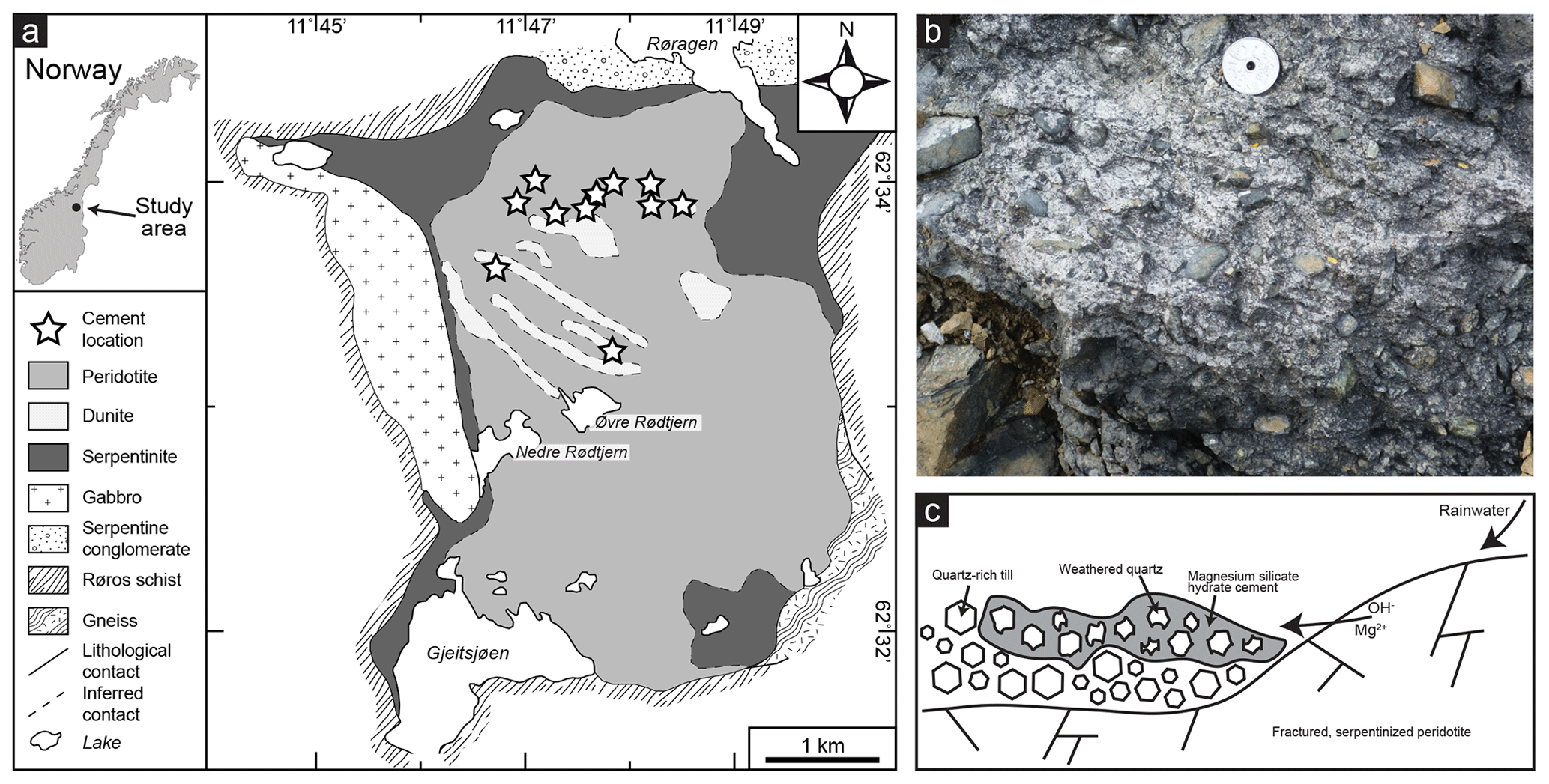
Figure 1(a) Simplified geological map of the Feragen ultramafic body (after Moore and Hultin, 1980; Beinlich and Austrheim, 2012; de Ruiter and Austrheim, 2018). Note that felsic till is present on top of the bedrock. (b) Field photo of the cemented rock that occurs at multiple localities in the area consisting of magnesium silicate hydrate cement and quartz-rich grains. (c) Schematic (not to scale) overview of the formation of the cemented rock, showing that rainwater becomes high in pH and rich in Mg as it reacts with the brucite-bearing ultramafic rocks. As this alkaline fluid enters the quartz-rich till, it leads to the dissolution of quartz and precipitation of magnesium silicate hydrate cement at the outer layer of the till.
Ultramafic mine tailings are efficient feedstocks for carbonation (Turvey et al., 2018). This is also the case at the Feragen ultramafic body where the tailings from the ancient chromium mines are coated with hydrocarbonates. The carbonation of the mine tailings starts 5–10 cm below the surface and is particularly abundant on the downfacing side of rock fragments. Carbonation also occurs inside the mineshafts. In mineshafts that have only one opening and thus little airflow, hydrocarbonates are found around the entrance of the mineshafts. Mines with a higher airflow due to multiple openings are carbonated along the entire shaft (Beinlich and Austrheim, 2012).
The ultramafic body is covered by unsorted and unconsolidated felsic glacial sediment, known as till, which is deposited on top of the ultramafic body and mixed with ultramafic rock fragments. The till occurs as moraines or as layers of rock fragments on the surface and originates from the Weichselian glaciation (115 to 11.7 ka), the last glaciation occurring in the area. The felsic material has a wide variety of sizes, ranging from sand consisting of single quartz grains to granitic boulders. The material consists mainly of quartz, but K-feldspar and mica are also abundant. The till locally contains fragments of ultramafic rock, which constitute serpentinized peridotite and dunite like the Feragen ultramafic body itself. Ultramafic fragments are especially abundant around the mine tailings of the abandoned chromium mines. At multiple localities spread over the area, felsic till and ultramafic rock fragments are cemented together and form a solid concrete-like rock (conglomerate) due to the precipitation of magnesium silicate hydrate cement (Fig. 1b). As described in detail by de Ruiter and Austrheim (2018), the cemented rocks can be found at localities where high-pH, Mg-rich fluids can accumulate and evaporate such as on terraces formed by frost heave and at the entrances to abandoned chromium mines, where fractured serpentinite allows for extensive high-pH, Mg-rich fluids and where the airflow through the mineshafts enhances evaporation (Fig. 1c). Cemented rocks are always limited to the upper 30 cm of the surface, as evaporation is required for precipitation. The localities with cement are usually less than 1 m2, and more than 10 localities have been identified in the area. The end of the Weichselian glaciation at 11.7 ka gives a timeframe for the deposition of the quartz and thus the possible start of dissolution. However, most of the cement is found along the walls of the mine trenches of the chromium mines, where it occurs both within and between the rocks of the mine tailing. This indicates that the cementation must have been initiated after the trenches were dug. It is known that the Feragen chromite mines were in operation between 1824 and 1939, indicating that the cementation started at most 200 years ago. Since microtextures tell us that the cement replaces quartz through a dissolution–precipitation mechanism (Putnis, 1992; de Ruiter and Austrheim, 2018), this allows us to estimate that the dissolution took place in a period of a maximum of 200 years.
Cemented rock samples from various localities in the area were collected and thin sections were made for microscopic analysis of the reacted quartz. Quartz-rich rock samples from the till without cement were also collected, and thin sections were made of inner parts of these rock samples to avoid reacted surfaces and obtain information about the initial quartz. The thin sections were studied by optical microscopy to observe the general microstructure of the samples and deformation features of quartz. In addition, the microstructures were analysed and backscattered electron (BSE) images were obtained by scanning electron microscopy (SEM) using a Hitachi SU5000 FESEM operating with an acceleration voltage of 15 kV. The SEM was equipped with energy-dispersive X-ray spectroscopy (EDX) used for element identification and semi-quantitative analysis of the cement and other minerals. The thin sections were coated with carbon before analysis with SEM. Rock samples of about 0.5 cm3 coated with gold were studied with the same SEM in secondary electron (SE) mode to observe surface textures and morphologies.
To observe the structures on the nanoscale, electron-transparent thin foils were obtained by focussed ion beam (FIB) preparation using a JEOL-JIB 4500 FIB-SEM. The foils were made from a thin section analysed with SEM at a location where quartz was partly dissolved and replaced by cement. The thin section was coated with gold before the FIB procedure. The electron-transparent samples were analysed with a JEOL JEM-2100F transmission electron microscope (TEM) operating with an acceleration voltage of 200 kV. Both cement and quartz are known to be beam-sensitive, so careful handling during the TEM sessions was required. The exposure and focussing of the beam onto the samples were limited as much as possible before images were obtained. This did not allow for images with a resolution higher than those presented in this work.
Whole rock geochemical analyses were performed by Actlabs Laboratories Ltd. using the lithium metaborate–tetraborate fusion ICP whole rock ICP/MS package (https://www.actlab.com, last access: 1 February 2019). FeO was determined through titration.
The cemented rocks are composed of felsic rock fragments, containing mainly quartz, K-feldspar and mica, and ultramafic rock fragments, containing mainly serpentine and minor olivine, with cement in between. Aside from the cement, quartz is the most abundant phase and is present as single grains, polycrystalline quartz aggregates and in rock fragments also containing feldspar and mica in addition to quartz. The quartz grains, which are the potential source of silica for the magnesium silicate hydrate cement, were studied in detail, and the results are listed below together with observations of the non-reacted initial quartz, i.e. the protolith. The other minerals present in the cemented rocks are not specifically addressed in this work.
4.1 Microstructures of initial quartz
Quartz present in non-cemented rock located away from the ultramafic rocks, where it is unlikely that high-pH fluid could have affected the quartz and therefore where no cement was found, shows the initial appearance of the quartz. The protolith can also be observed in large (>1 cm) quartz fragments inside the cemented rock, which do not show signs of dissolution in the centres. Many quartz fragments are characterized by small (∼ 50 µm) equigranular polygonal neoblasts with straight grain boundaries together with large (∼ 500 µm) unrecrystallized grains with undulose extinction and sometimes subgrains (Fig. 2a–b), which is typical for dynamic recrystallization (Passchier and Trouw, 2005). This indicates that the quartz has been severely plastically deformed and that dislocation glide and recovery resulted in the formation of subgrains. In addition, essentially all quartz grains, including the dynamically recrystallized grains, show undulose extinction, indicating plastic deformation.
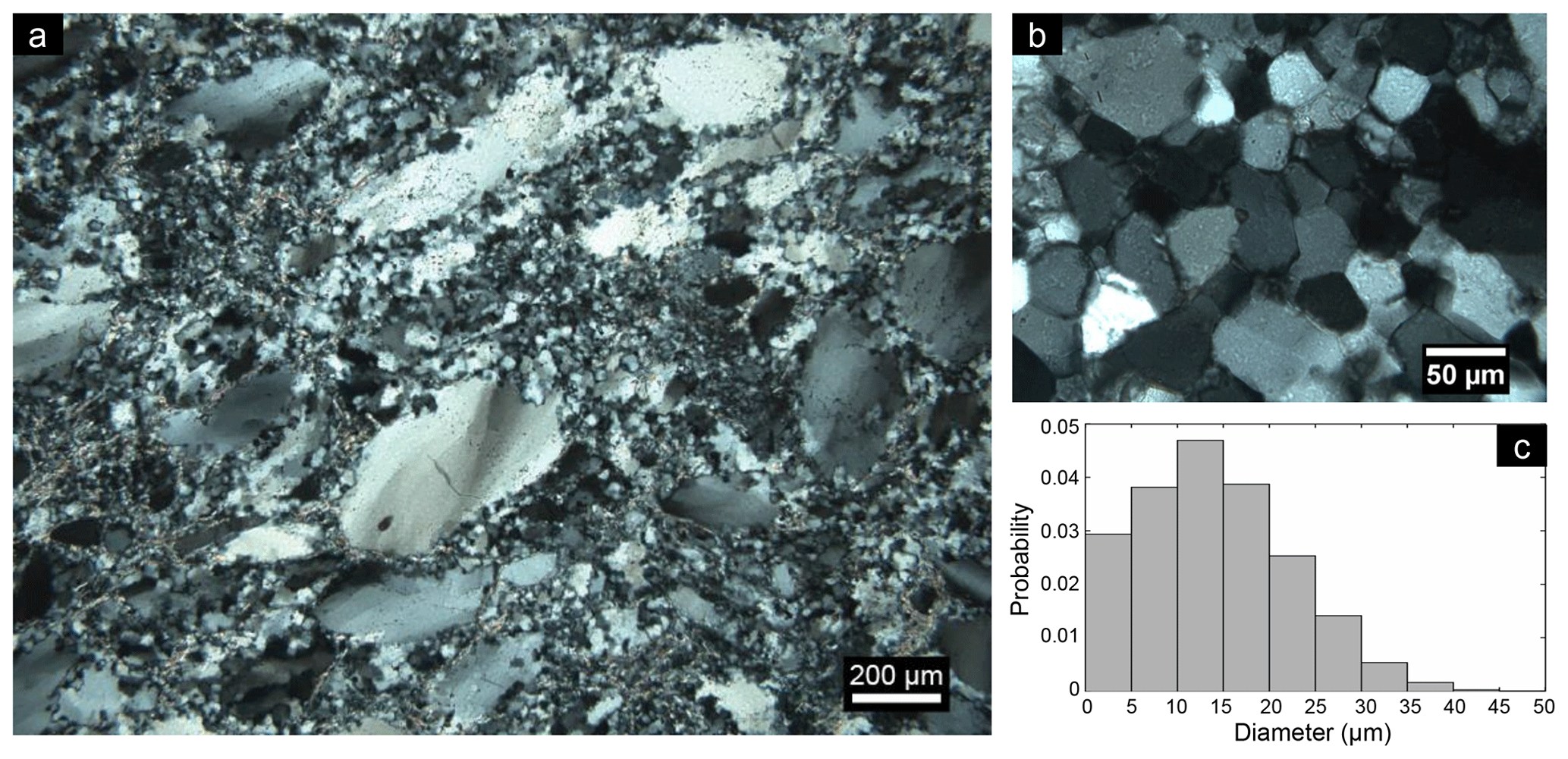
Figure 2(a) Optical micrograph with cross-polarized light of recrystallized quartz from Feragen, as indicated by the presence of small equigranular polygonal neoblasts with straight grain boundaries together with large unrecrystallized grains with undulose extinction. This sample has not been weathered or cemented. (b) Zoomed-in view of the polygonal grains. (c) Probability density histogram of the grain size of recrystallized single quartz grains obtained from cemented rocks (n=1730).
A range of recrystallization textures are present, indicating subgrain rotation and grain boundary migration and larger granitic fragments in the cemented rock locally have a mylonitic texture. The newly recrystallized quartz grains and subgrains vary in size from 1 to 50 µm (Fig. 2c). The subgrains or recrystallized grains within quartz are clearly visible with TEM as neighbouring grains have a slight change in orientation which can be observed when tilting the sample in bright-field mode. In diffraction mode, it can be observed that the zone axes of two neighbouring grains have a difference in orientation around 10–15∘. TEM also reveals the presence of many pores and dislocations within the quartz.
4.2 Characteristics of weathered quartz
4.2.1 Microstructures
Quartz grains embedded within the magnesium silicate hydrate cement often have irregular grain boundaries, and the cement is present at fractures and pore spaces within the grains (Fig. 3a). Penetration of the cement into the grains divides one grain into multiple smaller grains as it forms pathways into the grain (Fig. 3a). Comparing cross-polarized light (XPL) optical micrographs with BSE micrographs of the same grain shows that the cement pathways coincide with (sub)grain boundaries of recrystallized grains. At those locations, it can be observed that the outer boundaries of the recrystallized grains are partly dissolved and that cement is present. Therefore, the cement pathways typically have a polygonal shape (Fig. 3a) similar to the initial quartz grain boundaries (Fig. 2b). The original polycrystalline quartz grains are frequently partly or completely disintegrated into single grains, which provides a network of polygonal quartz grains surrounded by magnesium silicate hydrate cement layers of around 5–10 µm (Fig. 3b). This can sometimes be observed at the outer boundary of larger quartz fragments, while the inner part is not infiltrated by cement (Fig. 3b). Pore spaces between the cement and quartz are a common feature within the cemented rock. This creates a honeycomb-like texture within the cement, corresponding to the shape of quartz grains (Fig. 3c). Relics of quartz grains can be found within these honeycomb-like pore spaces (Figs. 3c and 4c).

Figure 3BSE images of the relation between quartz (Qtz) and magnesium silicate hydrate (Msh) cement. (a) Cement is present at the grain boundaries within a quartz fragment. Note the hexagonal shape typical for recrystallized quartz. (b) Disintegrated quartz grains with cement between them at the outer boundary (lower right) of a large millimetre-sized grain, while the inner part (upper left) is mainly intact. (c) A quartz fragment that is disintegrated into small grains surrounded by cement on the outer boundary, some of which have dissolved and left behind pore spaces (black) in the shape of the grains. Note that while the left side of the fragment indicates dissolution of disintegrated quartz grains, the right part indicates only disintegration, and the middle and bottom part indicate the original grain.
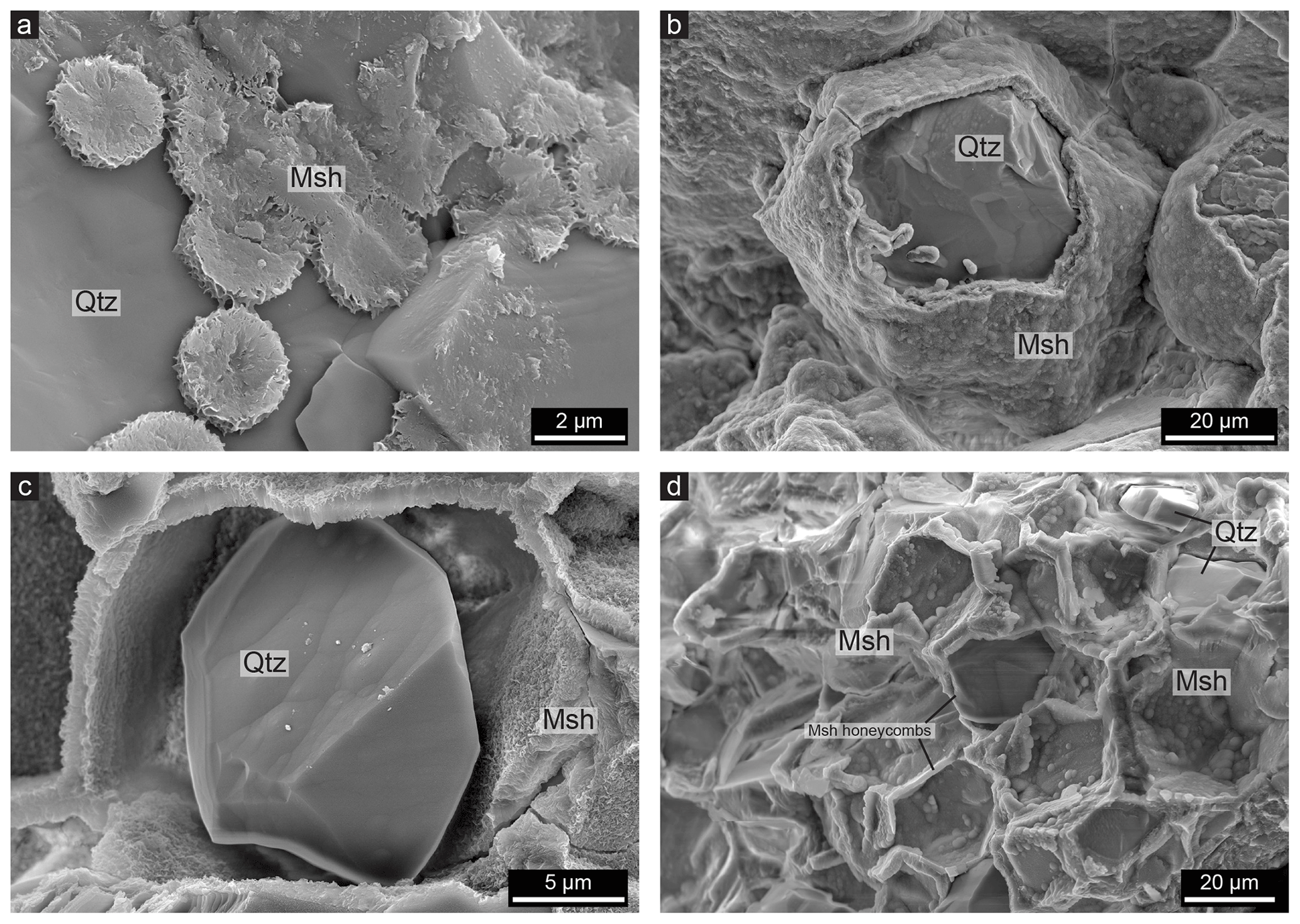
Figure 4SE images of non-polished whole rock samples showing quartz (Qtz) with a magnesium silicate hydrate (Msh) coating. (a) At initial stages of cement precipitation, it forms in disc shapes on the quartz surfaces. As the cement forms on the quartz surface, it takes over the topography of the grains, giving the cement a smooth outer surface but a flaky inner texture. (b) A hexagonal quartz grain almost completely covered with cement. (c) A quartz grain that started to dissolve after the cement was precipitated, leading to a void between the quartz and the cement layer. (d) Quartz grains that are completely dissolved; a network of mostly empty pore spaces in the shape of honeycombs is produced.
The cement forms a coating around the quartz grains (Fig. 4a–b). Figure 4a shows that in the initial stages the layer does not cover the whole surface but is rather present as micrometre-sized discs on the surface. However, as shown in Fig. 4b, the cement often coats the complete quartz grains with a layer a few millimetres thick and is also present between two grains as shown in Fig. 4b, which resembles similar situations as in Fig. 3a–b. In Fig. 4b, the polygonal shape of the quartz grain coated with cement is clearly visible, again showing that the cement forms around the recrystallized quartz grains. The cement is usually smooth at the interface since it takes over the topography of the quartz surface, resulting in a smooth layer that also fills up etch pits, which are common on the surfaces. The cement layer, however, has a flaky texture at the inside (Fig. 4a), and botryoidal textures are also commonly present on the outer interface of the cement layer (Fig. 4b). It can be observed that the cement is porous due to the flaky texture.
The void between quartz grains and the cement coating as shown in Fig. 3c is also visible in Fig. 4c, indicating that the quartz grain was reduced in size after the cement formed the honeycomb-shaped coating around the grain. Empty honeycombs are also a common feature within the cemented rock as shown in Figs. 4d and 3c, which sometimes contain remnants of quartz grains. This leads to a grid of cement which follows the shape of grain boundaries. A void between quartz and cement can typically only be observed when the cement layer has a thickness of a least 5 µm, although it should be noted that much larger areas of cement occur within the rocks without such large pore spaces. Various stages of the honeycomb texture can be observed within one thin section and even within one quartz grain. For example, the outer part of a quartz grain may consist of empty honeycombs, while in the inner part the cement is present at the grain boundaries without a visible void between the quartz grain and the cement (Fig. 3c). The honeycomb pore spaces can be up to 50 µm in diameter, corresponding to the size of the recrystallized quartz grains and subgrains. Lastly, honeycomb textures wherein the pore space is filled with magnesium silicate hydrate cement are present (Fig. 5). This can be observed since the outlines of the honeycomb texture have a slightly different contrast in BSE images, indicating a different density, even though the complete grains consist of cement (Fig. 5).
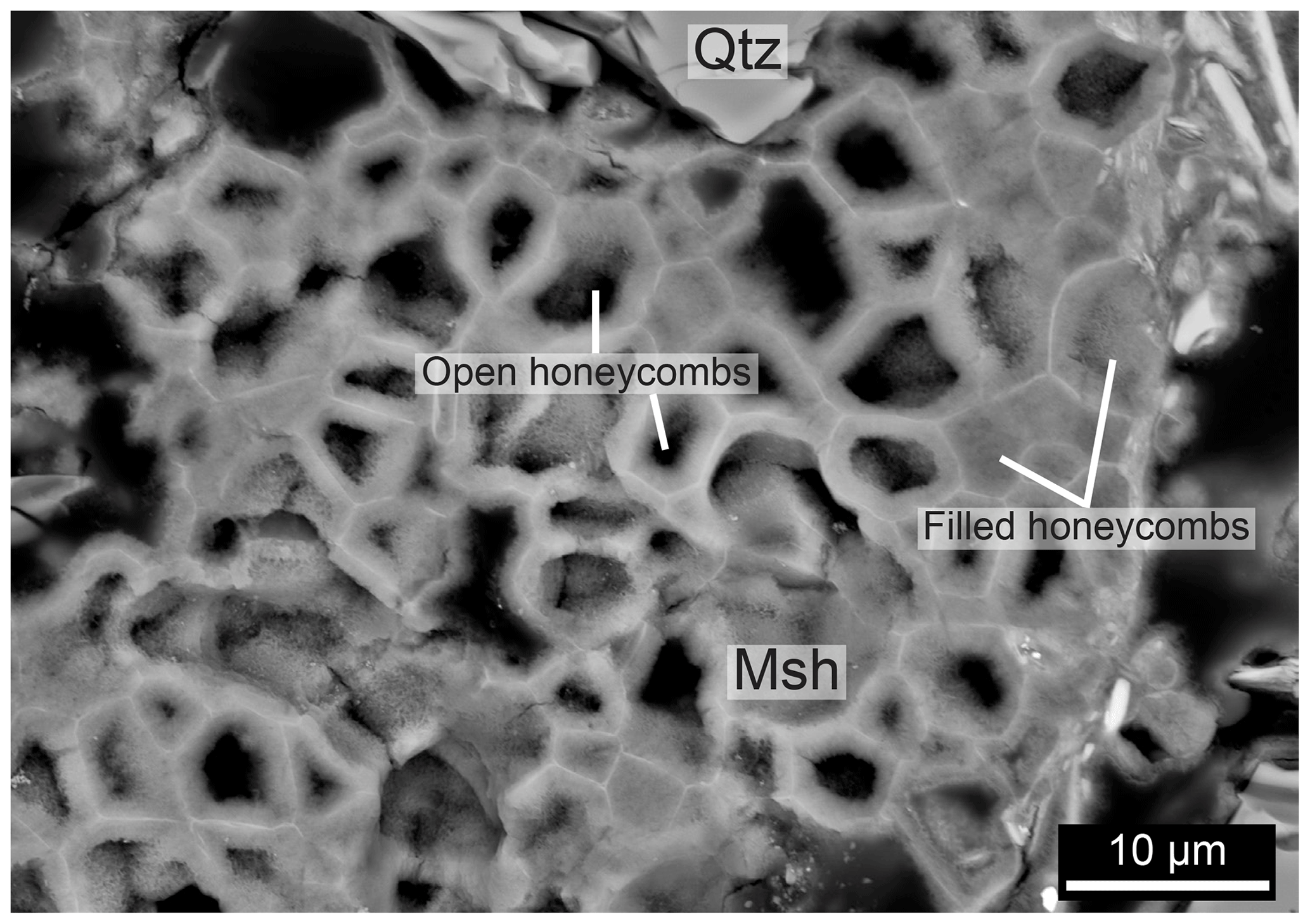
Figure 5BSE images of honeycomb texture with typical 2–10 µm diameter pore spaces. The texture consists of magnesium silicate hydrate cement (Msh), and the interior is either empty (black) or filled with cement (grey) with a different contrast, signifying a different density. The size of the individual honeycomb cells does not seem to correlate with the cell being filled or not. No quartz (Qtz) is present, except at the top of the figure.
4.2.2 Morphology
SE images of bulk samples of cemented rock show that etch pits are abundant on the surfaces of the quartz grains that are surrounded by magnesium silicate hydrate cement (Fig. 6). Both rectangular (Fig. 6b) and triangular etch pits (Fig. 6d) occur on different surfaces. The rectangular pits vary in size from 0.1 to 4 µm, and smaller pits sometimes occur within larger ones. The triangular pits vary from 0.1 to 2 µm. Most etch pits have steep edges, and the deeper pits often have a step or spiral structure. The etch pits on one surface always have the same orientation and are sometimes aligned, as can be observed in Fig. 6b and d. The density of the etch pits varies per grain; for example, in Fig. 6b the etch pit density is 1010 cm−2, and there is more reacted surface than non-reacted surface. Etch pits do not occur on every quartz grain; for example, the grain in Fig. 4c does not have etch pits even though dissolution has clearly taken place.
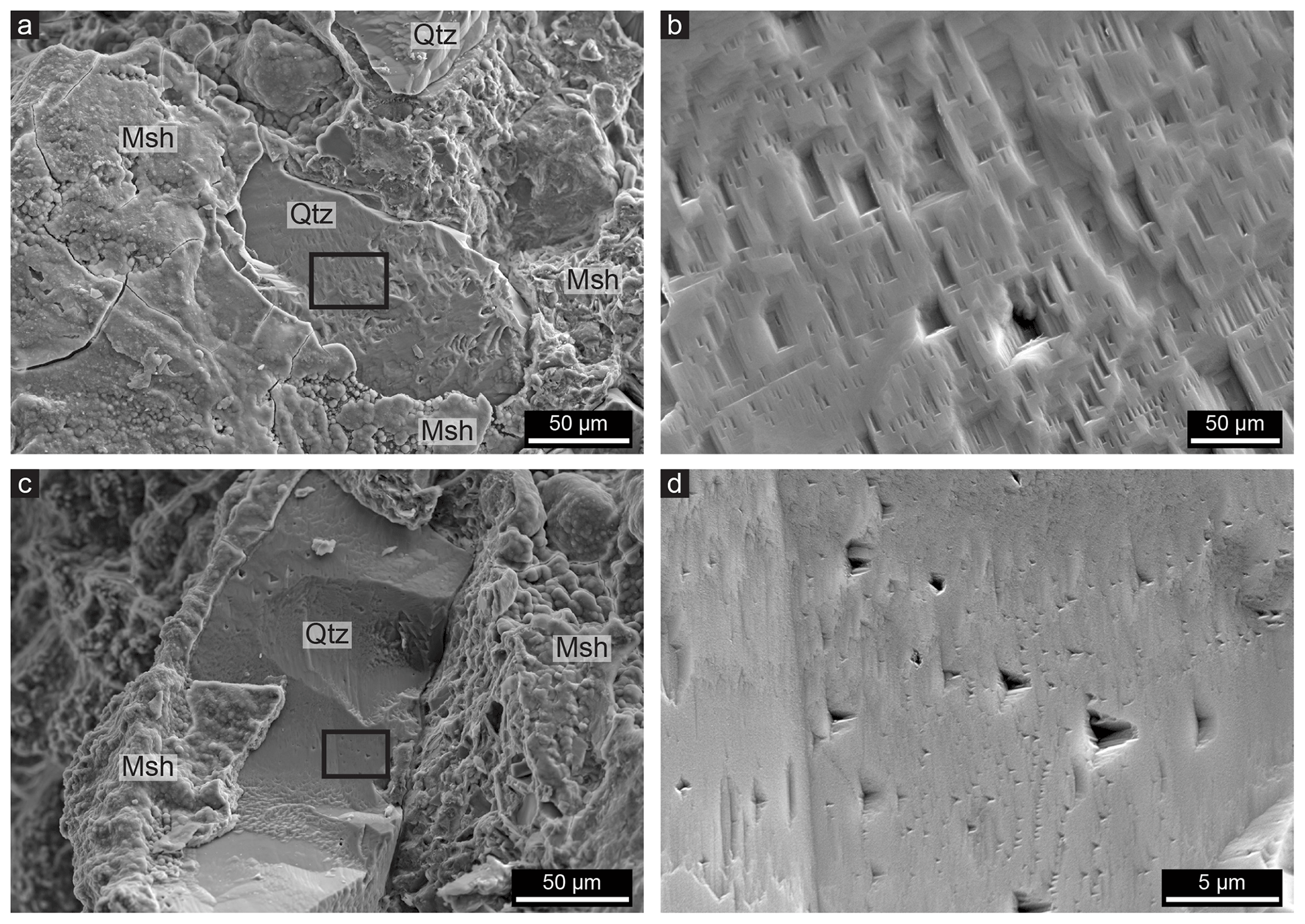
Figure 6SE images from SEM, showing etch pits on quartz (Qtz) grains that are embedded in magnesium silicate hydrate cement (Msh). (a) A quartz grain with rectangular etch pits on the surface; the box indicates the location of (b). (b) Rectangular etch pits of varied sizes; note that all have the same orientation and that some are aligned. The dislocation density is 1010 cm−2. (c) A quartz grain with triangular etch pits on the surface; the box indicates the location of (d). (d) Triangular etch pits on a quartz surface that vary in size but have an identical orientation; note that some of the smaller etch pits are aligned.
4.2.3 Nanostructures
Transmission electron microscopy of a quartz grain that is partly dissolved and surrounded by cement (Fig. 7a–b) shows that an amorphous silica layer of 100–200 nm is present at the interface (Fig. 7c). The amorphous layer occurs at all the outer boundaries of quartz present in the FIB foil. Different fragments of quartz grains are held together by the magnesium silicate hydrate in the studied sample, but there is often a void of 100–200 nm between the amorphous layer and the cement (see the bright areas in Fig. 7c). With TEM it can be observed that the magnesium silicate hydrate cement has a fibrous texture and that these fibres of the cement are attached to, and partly intergrown with, the amorphous layer. This makes the interface between the amorphous silica layer and the cement irregular. Quartz and the amorphous silica can easily be distinguished with TEM from the lack of crystalline diffraction pattern or contrast compared to the crystalline quartz. EDX indicates that the layer has the same Si-to-O ratio as the quartz grain, but whether the layer is hydrated or not is unclear. At internal grain boundaries within the quartz, there is also often a layer of amorphous material present with a thickness of around 30 nm (Fig. 7d). Based on the EDX data and diffraction, the layer is also amorphous silica and similar in composition to the amorphous layer at the outer interface of the quartz. As shown in Fig. 7d, the thin amorphous layer continues from the thicker amorphous layer at the outer interface and follows the grain boundary inwards for about 1.4 µm. At other grain boundaries, the amorphous layer can be found further inwards, but there are also grain boundaries that do not have any visible amorphous layer, especially further into the quartz.
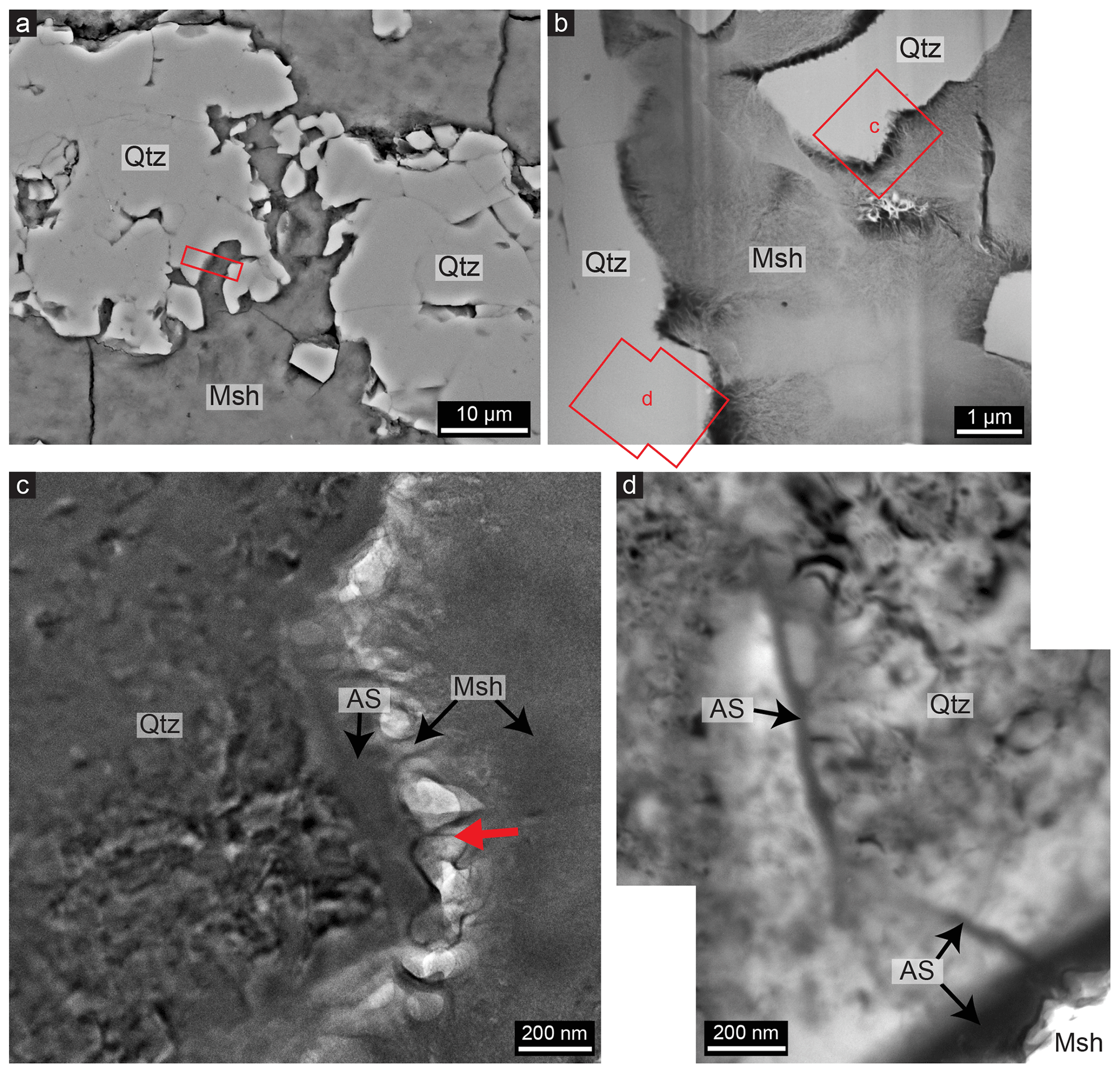
Figure 7(a) SEM image of weathered quartz (Qtz) surrounded by magnesium silicate hydrate (Msh); the rectangle indicates the location of the FIB thin film studied with TEM. (b) Scanning transmission electron microscopy (STEM) image giving an overview of the FIB thin film, showing the locations of (c) and (d) as well as the presence of quartz within the fibrous cement. (c) Bright-field TEM image showing that an amorphous silica (AS) layer of 100–200 nm is present around crystalline quartz that is surrounded by magnesium silicate hydrate cement. Note the presence of fringes indicating crystallinity in the quartz grain and the lack of those in the amorphous silica layer. The fibrous magnesium silicate hydrate is attached to the amorphous silica (e.g. at the red arrow), although pore spaces (the bright areas) are present in between. (d) Bright-field TEM image showing that a layer of amorphous silica of 30 nm is present between two quartz grains; it starts at the thicker amorphous layer on the outer boundary of quartz (lower right) where magnesium silicate hydrate is present, like the layer in (c), and follows the grain boundary for about 1.4 µm inwards, after which it disappears.
4.3 Composition of till and cemented rock
Two samples of till, consisting of sand and collected from a frost boil, were analysed for major elements and compared with the composition of a nearby rock that has been cemented with magnesium silicate hydrate (Supplement Table S1). High SiO2 (87.7 wt % and 89.6 wt % for the till and 72.8 wt % for the cemented rock) and low Al2O3 (4.5 and 4.2 for the till and 4.2 for the cemented rock) characterize the samples. The till and the cemented rock contain similar amounts of most oxides (Al2O3, TiO2, FeO, CaO, Na2O and K2O). However, the tillite contains a significantly high amount of MgO of 10 wt % compared to 0.8 wt % and 0.6 wt % in the two samples of till. The loss on ignition (LOI) value is also significantly higher in the tillite (9.4 wt %) compared to the two till samples (0.7 wt % and 0.5 wt %).
5.1 Geochemistry and magnesium silicate hydrate formation
Till is produced by mechanical weathering and is assumed to represent a robust average composition of the upper continental crust (Goldschmidt, 1933; Gaschnig et al., 2016). The composition of the till deposited at the Feragen ultramafic body (Supplement Table S1) shows little to no geochemical signature from the underlaying ultramafic body, suggesting that the glacier collected bedrock material from an area much wider than the Feragen ultramafic body. We can therefore not relate the till to a nearby lithology. The similarity in composition between the till and the cemented rock for most oxides (besides MgO and SiO2) suggests that the till is the protolith of the cemented rock, in accordance with the microstructural observations. The composition of the cemented rock compared to the till (reduced SiO2 and increased MgO and LOI) supports the hypothesis that quartz within the till is replaced by magnesium silicate hydrate cement. The addition of Mg to the cement formation process can be related to weathering of the peridotite. At the Feragen ultramafic body, meteoric water has a high pH and is rich in Mg2+ due to the chemical weathering of ultramafic rock, which is associated with the dissolution of brucite (Mg(OH)2). This is clearly visible in the weathering rind, which lacks brucite in contrast to the inner part of the rocks (Beinlich and Austrheim, 2012; Ulven et al., 2017), while olivine and serpentine appear unaffected. This also indicates that no Si from the bedrock was added during cement formation and that the Si in the magnesium silicate hydrate cement must originate from the till. The ultramafic body of Feragen crops out over about 14 km2 and represents a large reservoir of brucite. The dissolution of brucite in the outer rims of the ultramafic rocks is a fast process (Pokrovsky and Schott, 2004; Hövelmann et al., 2012), and thus the surface water will usually be in, or close to, equilibrium with brucite, meaning the pH will be above 10. The cement forms through the interaction of high-pH, Mg-rich meteoric water resulting from dissolution of brucite during chemical weathering of the serpentinized peridotite (Beinlich and Austrheim, 2012; Ulven et al., 2017).
5.2 Quartz dissolution and the role of grain boundaries
The microstructural observations within the cemented rock suggest that the outer boundaries of the recrystallized quartz grains are partly dissolved and have been replaced by magnesium silicate hydrate cement (Figs. 3a, b and 4a, b). As cement seems to follow the shape of the grain boundaries, is leads to a honeycomb-structured grid of cement. The frequently observed voids between quartz and the cement coating (Fig. 4c), as well as the empty honeycomb structures which sometimes contain relics of quartz (Figs. 3c and 4d), suggest that quartz must have been dissolved during or after cement precipitation. It also indicates that quartz dissolution is not always accompanied by cement precipitation, although completely filled honeycomb structures indicate that quartz grains of about 50 µm are completely replaced by cement (Fig. 5).
Magnesium silicate hydrate cement can often be found along the walls of the mine trenches in the chromium mines, where it occurs between the rocks of the mine tailings, indicating that it must have been precipitated after the trenches were made, which is about 200 years ago. We observed that quartz grains with a diameter of 50 µm within the cemented rocks are completely dissolved and (partly) replaced by magnesium silicate hydrate cement at surface conditions in a subarctic climate. Some of these cemented rocks occur in the mine tailings of mines that were in operation about 200 years ago, indicating that the grains dissolved in less than 200 years.
The solubility and dissolution rate of quartz increases rapidly with increasing pH, especially above a pH of 10 (Brady and Walther, 1990; House and Orr, 1992). Rimstidt (2015) used multiple experimental studies to determine a rate equation for quartz dissolution. Using this equation, we calculate the assumed dissolution rate of quartz in the Feragen area. Inserting the highest measured pH and Na+ concentration of 10.6 and mol L−1 (Beinlich and Austrheim, 2012), respectively, a temperature of 1 ∘C (the mean annual temperature – Norwegian Meteorological Institute), and assuming a continuous contact with the solution, the equation yields a quartz dissolution flux of mol m−2 s. However, our microstructural observations show that a quartz grain with a diameter of 50 µm dissolves in 200 years. This gives a dissolution flux of 1.75 × 10⁻¹⁰ mol m−2 s (calculated using equations of Lasaga, 1984). The dissolution rate observed in the Feragen area is thus 3 orders of magnitude higher than the dissolution rate predicted by experimental studies. Additionally, our predicted rate is calculated using the most favourable values, implying that the actual difference between predicted and observed rates might be even higher. Inserting the average Na+ concentration and pH values instead of the highest measured values, the experimentally established rate equations yield a flux of 4.2 × 10⁻¹⁴ mol m−2 s, which is 4 orders of magnitude lower than the observed dissolution rate. It could be speculated that the pH of the solution may increase above 10.6 due to evaporation, which will lower the difference between the predicted and observed dissolution rate.
The cemented rocks found away from the mines could not have started to form before the end of the Weichselian glaciation (11.7 ka). A quartz grain of 50 µm that has completely dissolved during this time span would nevertheless still indicate a rate faster than predicted by the rate equation: 3.0 × 10⁻¹² mol m−2 s. This discrepancy is in contrast to the typically observed difference in dissolution rates of silicate minerals between field data and experimental data; the latter usually suggests higher rates (White and Brantley, 2003; Brantley, 2005).
At high-pH conditions, aqueous silica and Mg2+ are known to precipitate together from surface water to form Mg-silicate phases (Tosca and Masterson, 2014). Hence, the cement, a hydrous Mg-silicate, precipitates on the grain boundaries where quartz has been dissolved and forms a layer that surrounds the quartz grains. That the dissolution of quartz proceeds faster in our natural case than predicted by experiments might be related to the coupling between the dissolution and the precipitation of a new phase at the surface of the quartz. The new phase, the cement, forms within the interfacial fluid after quartz dissolution and acts as a sink for dissolved silica, which subsequently enhances the further dissolution of quartz (Anderson et al., 1998a, b; Schaefer et al., 2018).
The dissolution and replacement of polycrystalline quartz grains many times larger than 50 µm can occur within the same time span since the dissolution starts at the internal grain boundaries or subgrain boundaries, which are present due to deformation and recrystallization at an earlier stage (Fig. 2b). This indicates that fluids penetrate polycrystalline grains along the grain boundaries (Jonas et al., 2014). This is likely to be accomplished by intergranular diffusion via fluid films between the grains (Renard and Ortoleva, 1997; De Meer et al., 2005). The combination of dissolution on the surfaces of the grains and diffusion via intergranular fluids has been proposed as the main mechanism for the chemical weathering of quartzite and sandstone (Piccini and Mecchia, 2009; Wray and Sauro, 2017). In quartz-rich rock, the intergranular fluids will be rich in H4SiO4 (silicic acid), the main form of dissolved silica occurring in nature (Iler, 1979). Since the concentration of silicic acid in the meteoric water outside the rock or in larger fractures within the rock is much lower, the silicic acid will diffuse from the intergranular space to the fractures and larger pore spaces where the meteoric water is present (Piccini and Mecchia, 2009). This favours diffusion of silica away from the intergranular fluids and enhances the dissolution of quartz at the intergranular surfaces within the rock.
Thus, the microstructure of the quartz protolith is also likely to contribute to the dissolution rate. Owing to the deformation and subsequent dynamic recrystallization, the surface area would be significantly increased, and hence the total amount of dissolved quartz can be much higher than for non-recrystallized quartz. As shown in Fig. 3a, the cement first forms at the grain boundaries, leading to the disintegration of recrystallized polycrystalline quartz grains (Fig. 3b) multiple millimetres in diameter to single quartz grains between 1 and 50 µm, the size of the recrystallized grains (Fig. 2c). These grains are sometimes dissolved completely (Fig. 3c). Fractures and inclusions are also starting points of cement precipitation.
5.3 Etch pits
Triangular and rectangular etch pits are abundant on quartz within the cement (Fig. 6) and are related to the rhombohedral and prismatic surfaces of quartz crystals, respectively (Yanina et al., 2006). A relationship between the location where dislocations intersect the mineral surface and the nucleation of etch pits on quartz has been widely reported (Blum et al., 1990; Gratz et al., 1991; Yanina et al., 2006). Many of the quartz grains within the cemented rock show undulose extinction, including the recrystallized grains, indicating the presence of dislocations (Fig. 2a). The initial non-cemented quartz grains show the same features, indicating that crystal plastic deformation occurred before the cementation and is not related to the cementation process. The deformation could partly be induced by the glaciation due to subglacial shearing, which is common for sediments below glaciers (Boulton et al., 2001; Evans et al., 2006). We speculate that the subglacial shearing acts as a ball mill that mechano-chemically activates the quartz and increases its dissolution rate.
Although increased dislocation density may increase the number of etch pits during dissolution, it is not clear whether this influences the bulk dissolution rate. Multiple studies concluded that the influence of dislocations on the total dissolution rate of quartz is insignificant (Blum et al., 1990; Gautier et al, 2001; Lasaga and Luttge 2001). However, experiments showed a relationship between the pH and the number of etch pits, indicating that most etch pits form when the pH, and thus the dissolution rate, was highest (Knauss and Wolery, 1988). Brantley et al. (1986) showed that if the silica concentration is far below a critical concentration, etch pits grow rapidly, while at a higher concentration dissolution occurs without etch pits. The high abundance of etch pits on the quartz surface of grains in the cement thus indicates dissolution that is far out of equilibrium and a high dissolution rate. The aligned etch pits in Fig. 6b and d might represent deformation bands or subgrain boundaries, since these are characterized by the concentration of dislocations.
5.4 Amorphous silica layers
The amorphous silica layer present between the quartz and cement (Fig. 7c) must be related to the dissolution process since it occurs at the outer boundary of quartz grains that are partly dissolved during cementation (Fig. 7a). The formation of an amorphous silica layer as a result of dissolution has been reported for other silicate minerals in multiple experimental studies (Casey et al., 1993; Hellmann et al., 2003; Daval et al., 2011; Ruiz-Agudo et al., 2012) and for natural rock samples (Nugent et al., 1998; Zhu et al., 2006). The mechanisms that form this layer and the influence they have on the dissolution rate of silicate minerals are a matter of debate. Most recent experimental studies indicate that the layers form due to an interface-coupled dissolution–precipitation process (Hellmann et al., 2012; Ruiz-Agudo et al., 2012, 2016). These studies show that the layer forms because the fluid layer at the interface becomes saturated with silica upon dissolution of the silicate surface, even though the bulk fluid is far undersaturated, so that amorphous silica subsequently precipitates at the interface. Studies have indicated the co-occurrence of dissolution through etch pit formation and amorphous material precipitation (Jordan et al.,1999; Ruiz-Agudo et al., 2012), similar to the observations of quartz interfaces in this study. However, it has not been shown before that this mechanism is also involved in quartz dissolution, although the growing amount of literature on such surface altered layers suggests that they widely occur on various silicate minerals. Moreover, Pope (1995) discovered amorphous silica layers on weathered quartz from moraine soils and observed these layers at internal grain boundaries and along fractures. Geochemical calculations performed with PHREEQC (Parkhurst and Apello, 1999) indicate, however, that if quartz dissolves in a high-pH solution, the solution will remain undersaturated with respect to amorphous silica (Supplement Fig. S1). Quartz dissolution by itself thus probably cannot supersaturate the solution with respect to amorphous silica. External factors that could supersaturate the interfacial fluid such as evaporation and freeze–thaw cycles must therefore play a role. This is also suggested by the cement being limited to the surface, where evaporation takes place. The supersaturation thus seems to be generated by a combination of quartz dissolution and evaporation, resulting in the precipitation of amorphous silica.
It is well known from experiments that amorphous silica and brucite will react to magnesium silicate hydrate cement (Zhang et al., 2012), and the geochemical calculations (Supplement Fig. S1) also show that if quartz or amorphous silica dissolves in a solution that is in equilibrium with brucite, the solution will be supersaturated with respect to multiple Mg-silicate phases. It is thus likely that in our natural case, the amorphous silica is incorporated into the magnesium silicate hydrate cement under Mg-rich and high-pH conditions. Whether the amorphous silica is directly incorporated into the cement or dissolves first is unclear, although experiments have shown that the formation of Mg-silicates often involves poorly crystallized, or gel-like, precursors or intermediate phases (Steefel and Van Cappellen, 1990; Baldermann et al., 2018) that transform into more crystalline phases due to progressive dehydration, which involves the loss of weakly bonded surface water (Tosca and Masterson, 2014). Such dehydration processes might be the result of evaporation. It is unclear why amorphous silica precipitates first and magnesium silicate hydrate does not precipitate directly. This could possibly be related to the low nucleation barrier of amorphous silica making it more favourable to precipitate amorphous silica on the interface rather than magnesium silicate hydrate or the different thermodynamic properties that the fluid boundary layer has compared to the bulk fluid. Since the cement is porous and nanocrystalline, diffusion can continue once a layer has built around the quartz grains (Fig. 4b), making it possible for quartz to continue to dissolve and for the cement layer to become thicker (Fig. 4c–d). This could also be accommodated by fluid moving through the small void between the cement and the quartz (Fig. 7c). The porosity of the cement has not yet been quantified.
Amorphous layer precipitation is usually thought of as slowing down or ceasing dissolution, since it covers the reactive surface (Daval et al., 2011). However, the reaction of amorphous silica to porous magnesium silicate hydrate exposes the surface again and could thus lead to more dissolution and subsequent amorphous silica precipitation, creating a continuous cycle of dissolution and precipitation (Ruiz-Agudo et al., 2012). Another possibility is that the amorphous layer dissolves at the outer boundary, while quartz dissolves and reprecipitates as amorphous silica at the inner boundary due to the presence of a fluid layer between the quartz and the amorphous layer (Hellmann et al., 2012). Both theories would result in the continuous dissolution of quartz regardless of the amorphous silica precipitation.
The intergranular thinner amorphous layers again indicate the infiltration of the reactive fluids and the start of dissolution at the grain boundaries (Fig. 7d). Although the observations of intergranular amorphous layers are limited since they can only be observed with TEM, it is likely that they will develop into cement layers as in Fig. 3a. The possibility of infiltration will accelerate the replacement reaction from quartz to cement, and these findings emphasize the importance of preconditioning the quartz by deformation to provide intergranular fluid pathways.
5.5 Mass transport and cement precipitation
When the cement layer around a quartz grain has reached a thickness of about 5 µm, the quartz is often separated from the cement by a void. This suggests that the quartz grains continue to dissolve while the cement precipitation ceases, which leads to honeycomb textures as can be observed in Fig. 4c. The formation of the honeycomb texture is remarkably similar to the formation of cavities in experimentally produced magnesium silicate hydrate cement that is made with silica fume particles, whereby the cement precipitates on the surface of these particles, after which the particles dissolve and no cement fills the gap (Zhang et al., 2018).
Ruiz-Agudo et al. (2016) suggested that whether amorphous silica will precipitate as a result of the dissolution of silicate minerals depends on the ratio between reactive surface area and mass transport, since the dissolution rate needs to be fast compared to the diffusion of dissolved ions to the bulk solution to create a saturated fluid layer. This suggests that a low flow rate is required for the precipitation of amorphous silica and hence for subsequent precipitation of cement. The lack of cement precipitation inside the honeycombs might therefore be related to a high flow rate and diffusion due to larger pore spaces, and it indicates the release and transport of silica instead of the precipitation of amorphous silica. At confined spaces like grain boundaries, transport of silica away from the dissolving surface is limited; amorphous silica can precipitate, and thus cement can form. However, if quartz is replaced by porous cement the permeability increases. This might enhance the flow rate and the transport of silica and magnesium so that the cement no longer can precipitate (Fig. 4c). In some cases when several neighbouring grains dissolve simultaneously, local supersaturation with respect to the cement phase is maintained, and the cement continues to precipitate as the entire quartz grain dissolves, leading to complete replacement (Fig. 5).
Disruptions at the quartz–cement interface might also lead to enhanced fluid transport. Observations similar to the cement honeycombs have been made for pyroxene and amphibole that have been weathered to clay minerals (Proust et al., 2006; Velbel and Barker, 2008). Velbel and Barker (2008) described the continuous dissolution of pyroxene after the outer layer has been transformed to smectite and ascribed this to mechanical disruption at the smectite–pyroxene interface due to hydration episodes that lead to tensional forces. A rupture between the smectite and the pyroxene subsequently improves the fluid access, and thus mass transport and dissolution of the pyroxene are favoured. From de Ruiter and Austrheim (2018) it is known that the magnesium silicate hydrate cement phase is related to the clay minerals kerolite and stevensite, the latter being an Mg-smectite that is known to shrink and swell with hydration cycles. In addition to the hydration cycles, freeze–thaw cycles could play a role in the disruption at the cement–quartz interface. Besides changes in fluid flow, chemical changes in pore fluids might also play a role in the formation of the honeycomb pore spaces. The geochemical calculations show that the pH of the solution will decrease with the continuation of quartz dissolution (see the Supplement). This would locally increase the solubility of the cement in the cavities between the cement and quartz, and its precipitation might therefore slow down or cease.
The precipitation of cement between different rock fragments instead of directly around quartz could be accomplished by the transported silica, leading to the cementation of the rock fragments and grains and hence the formation of a solid rock. This cement likely precipitates from solution upon evaporation, as is indicated by the fact that cementation is limited to the surface, which is comparable to the formation of other Mg-silicate phases (Tosca and Masterson, 2014). Mg2+ is present in the meteoric fluid due to weathering of brucite but must be transported through surface water or groundwater before precipitating as cement, during which part of it is lost in the discharge of water. Hence, it is difficult to make a mass balance based on the observations. Furthermore, other minerals might contribute to the Si and Mg concentration in solution. For example, it can occasionally be observed that feldspar is also replaced by magnesium silicate hydrate cement (de Ruiter and Austrheim, 2018).
Taking all the observations into account we propose that the dissolution of quartz and the precipitation of cement occur through the following steps: (1) the bulk fluid has a high pH and is rich in Mg2+ due to brucite dissolution; (2) quartz dissolves (through etch pits) due to conditions that are far out of equilibrium; (3) the interfacial fluid layer at the quartz surface gets saturated due to quartz dissolution and evaporation, and amorphous silica precipitates; (4) the amorphous layer reacts with the high-pH, Mg-rich fluids to form magnesium silicate hydrate cement; (5) the fluid can still access the quartz surface since the cement is porous and the amorphous silica layer has now been removed by the reaction, so the process of quartz dissolution, amorphous silica precipitation and subsequent cement precipitation will continue; (6) changes in fluid flow rates and/or fluid chemistry could lead to the ceasing of cement precipitation and therefore the formation of honeycomb textures; (7) diffused silica and dissolved brucite can co-precipitate as cement at some locations away from the quartz surfaces, leading to cementation of the rock fragments. Recrystallization before this process has preconditioned the quartz by providing grain boundaries which can act as fluid pathways with confined conditions. These are the ideal conditions for the replacement process, leading to the relatively fast replacement of the intergranular grain boundaries of quartz by cement.
Another relevant and widely observed phenomenon associated with pressure solution that might play a role is the enhancement of quartz dissolution in the presence of mica or clay minerals like smectite (Hickman and Evans, 1995; Bjørkum, 1996; Schwarz and Stöckhert, 1996; Fisher et al., 2000). The reason for this phenomenon is still unclear, although multiple recent experimental studies suggested that electrochemical surface potentials play a key role and are more important than pressure itself (Meyer et al., 2006; Greene et al., 2009; Kristiansen et al., 2011); therefore, it could be a chemical rather than a mechanical process. This would mean that no significant pressures are required and that pressure is only needed to keep the surfaces in close proximity, since the diffuse electric double layers, which are on the nanometre scale, of both surfaces must overlap. As shown by Kristiansen et al. (2011), an opposing surface with a more negatively charged surface potential than quartz will increase the dissolution rate of quartz; moreover, the surface potential of mica decreases rapidly with increasing pH, leading to a much lower surface potential for mica than for quartz at a pH around 10. Mica is a representative 2:1 phyllosilicate mineral, so it is likely that other phyllosilicate minerals have similar values. The exact amount of pressure needed or involved in the dissolution is nevertheless unclear, and it therefore remains speculation whether the magnesium silica hydrate cement, which is a 2:1 phyllosilicate (Roosz et al., 2015; de Ruiter and Austrheim, 2018), will enhance the dissolution of quartz at ambient conditions by precipitating on the quartz surface and having a more negative electrochemical surface potential than quartz.
5.6 Relevance for synthetic magnesium silicate hydrate cement
Natural magnesium silicate hydrate cement is similar, both compositionally and structurally, to synthetic M-S-H cement (de Ruiter and Austrheim, 2018), and it is therefore reasonable to ask what we can learn from nature in our attempts to develop M-S-H cement for commercial use. M-S-H cement has been suggested as a low-CO2 cement that could replace Portland cement (Imbabi et al., 2012), although it is currently mainly of interest as a cement for the encapsulation of nuclear waste due to its pH being lower (9–10) than that of conventional Portland cement (>12) (Zhang et al., 2011, 2012). This is beneficial for the storage of, for example, Al-containing nuclear waste, which causes corrosion problems and the dangerous release of hydrogen gas when encapsulated in Portland cement (Zhang et al., 2012).
Human-made M-S-H cement is produced from a reactive Si source like silica fume, which is amorphous silica consisting of spherical particles about 150 nm in diameter. It is an expensive material even though it is an industrial by-product. One of the main challenges in the development of M-S-H cement for large-scale production is the need for a reactive silica source that is inexpensive and widely available. The natural example shows that M-S-H forms from micrometre-sized quartz grains that are preconditioned by deformation and recrystallization. Quartz mylonite is abundant in nature, and further testing may show if such quartz can compete with silica fume. The results of this study might provide the first steps to use widely available quartz in the production of M-S-H cement. Furthermore, a porous honeycomb-textured cement, as formed in nature, might be interesting in specific applications since honeycomb structures in general are known as relatively light but strong structures. The high-pH fluids needed to form natural M-S-H are formed by dissolution of brucite during weathering of serpentinized peridotite. Brucite is typically intergrown with serpentine and difficult to separate, although weathering processes effectively dissolve brucite and provide us with the high-pH, Mg-rich fluid.
Natural cement forms in a century during a fast process on a geological timescale. However, to make this process relevant to the cement industry the process must be accelerated. Further research has to focus on this aspect and look for possible catalysers. More research is furthermore needed to analyse the long-term durability of this material, although mechanical tests on M-S-H cement are promising as they show that the compressive strength can exceed conventional Portland cement and can be influenced by, for example, the Mg-to-Si ratio (Zhang et al., 2012; Jin and Al-Tabbaa, 2014).
Quartz dissolution in the weathering zone of an ultramafic complex can lead to the precipitation of magnesium silicate hydrate cement through interface-coupled dissolution–precipitation. The process involves the formation of a nanometre-scaled layer of amorphous silica, which acts as a precursor for the magnesium silicate hydrate phase. High-pH (∼ 10), Mg-rich fluids resulting from weathering of ultramafic rocks initiate the replacement process. The rate of quartz dissolution is about 3 orders of magnitude higher than experimentally derived rate equations suggest under the prevailing high-pH conditions. This discrepancy is likely caused by the precipitation of the cement within the interfacial fluids subsequent to quartz dissolution, as this acts as a sink for the dissolved material and therefore enhances dissolution. Preconditioning of the quartz by deformation further enhances the replacement process as it provides intergranular grain boundaries that could act as fluid pathways and therefore as starting points for the dissolution of quartz and precipitation of cement.
Data are available upon request.
Samples are available upon request.
The supplement related to this article is available online at: https://doi.org/10.5194/se-12-389-2021-supplement.
LdR carried out the experiments and fieldwork and prepared the paper with contributions from all co-authors. HA contributed to the fieldwork and experiments and supervised the project. AEG carried out the TEM experiments. DKD led the funding acquisition.
The authors declare that they have no conflict of interest.
In addition to funding from Horizon 2020, the project was supported by the Research Council of Norway through the Norwegian Centre for Transmission Electron Microscopy, NORTEM (197405/F50). We thank Ole Ivar Ulven for his assistance in the field and constructive discussions, Berit Løken Berg for the help with the scanning electron microscope, Tarjei Bondevik for his lessons on focussed ion beam sample preparation, Joanna Dziadkowiec for the helpful discussions on interfacial processes, and Andrew Putnis for his useful comments on the paper. The reviewers are thanked for their constructive comments that have helped to improve this paper.
This research has been supported by Horizon 2020 (grant NanoHeal (no. 642976)).
This paper was edited by Johan Lissenberg and reviewed by two anonymous referees.
Anderson, J. G., Doraiswamy, L. K., and Larson, M. A.: Microphase-assisted “autocatalysis” in a solid-liquid reaction with a precipitating product - I. Theory, Chem. Eng. Sci., 53, 2451–2458, 1998a.
Anderson, J. G., Doraiswamy, L. K., and Larson, M. A.: Microphase-assisted “autocatalysis” in a solid-liquid reaction with a precipitating product - II. Experimental, Chem. Eng. Sci., 53, 2459–2468, 1998b.
Baldermann, A., Mavromatis, V., Frick, P. M., and Dietzel, M.: Effect of aqueous ratio and pH on the nucleation and growth of sepiolite at 25 ∘C, Geochim. Cosmochim. Ac., 227, 211–226, https://doi.org/10.1016/j.gca.2018.02.027, 2018.
Beinlich, A. and Austrheim, H.: In situ sequestration of atmospheric CO2 at low temperature and surface cracking of serpentinized peridotite in mine shafts, Chem. Geol., 332–333, 32–44, https://doi.org/10.1016/j.chemgeo.2012.09.015, 2012.
Bjørkum, P. A.: How important is pressure in causing dissolution of quartz in sandstones?, J. Sediment. Res., 66, 147–154, 1996.
Blum, A. E., Yund, R. A., and Lasaga, A. C.: The effect of dislocation density on the dissolution rate of quartz, Geochim. Cosmochim. Ac., 54, 283–297, https://doi.org/10.1016/0016-7037(90)90318-F, 1990.
Boulton, G., Dobbie, K., and Zatsepin, S.: Sediment deformation beneath glaciers and its coupling to the subglacial hydraulic system, Quaternary Int., 86, 3–28, https://doi.org/10.1016/S1040-6182(01)00048-9, 2001.
Brady, P. V. and Walther, J. V.: Kinetics of quartz dissolution at low temperatures, Chem. Geol., 82, 253–264, https://doi.org/10.1016/0009-2541(90)90084-K, 1990.
Brantley, S. L.: Reaction Kinetics of Primary Rock-Forming Minerals under Ambient Conditions, in: Surface and Ground Water, Weathering, and Soils, edited by: Drever, J. I., Treatise on Geochemistry, 5, 73–117, https://doi.org/10.1016/B0-08-043751-6/05075-1, 2005.
Brantley, S. L., Crane, S. R., Crerar, D. A., Hellmann, R., and Stallard, R.: Dissolution at dislocation etch pits in quartz, Geochim. Cosmochim. Ac., 50, 2349–2361, https://doi.org/10.1016/0016-7037(86)90087-6, 1986.
Brew, D. R. M. and Glasser, F. P.: Synthesis and characterisation of magnesium silicate hydrate gels, Cement Concrete Res., 35, 85–98, https://doi.org/10.1016/j.cemconres.2004.06.022, 2005.
Casey, W. H., Westrich, H. R., Banfield, J. F., Ferruzzi, G., and Arnold, G. W.: Leaching and reconstruction at the surfaces of dissolving chain-silicate minerals, Nature, 366, 253–256, https://doi.org/10.1038/366253a0, 1993.
Daval, D., Sissmann, O., Menguy, N., Saldi, G. D., Guyot, F., Martinez, I., Corvisier, J., Garcia, B., Machouk, I., Knauss, K. G., and Hellmann, R.: Influence of amorphous silica layer formation on the dissolution rate of olivine at 90 ∘C and elevated pCO2, Chem. Geol., 284, 193–209, https://doi.org/10.1016/j.chemgeo.2011.02.021, 2011.
de Meer, S., Spiers, C. J., and Nakashima, S.: Structure and diffusive properties of fluid-filled grain boundaries: An in-situ study using infrared (micro) spectroscopy, Earth Planet. Sci. Lett., 232, 403–414, https://doi.org/10.1016/j.epsl.2004.12.030, 2005.
Dove, P. M. and Nix, C. J.: The influence of the alkaline earth cations, magnesium, calcium, and barium on the dissolution kinetics of quartz, Geochim. Cosmochim. Ac., 61, 3329–3340, https://doi.org/10.1016/S0016-7037(97)00217-2, 1997.
Evans, D. J. A., Phillips, E. R., Hiemstra, J. F., and Auton, C. A.: Subglacial till: Formation, sedimentary characteristics and classification, Earth-Science Rev., 78, 115–176, https://doi.org/10.1016/J.EARSCIREV.2006.04.001, 2006.
Fisher, Q. J., Knipe, R. J., and Worden, R. H.: Microstructures of Deformed and Non-Deformed Sandstones from the North Sea: Implications for the Origins of Quartz Cement in Sandstones, in: Quartz Cementation in Sandstones, edited by: Worden, R. H. and Morad, S., Special Publication of the International Association of Sedimentology, 29, 129–146, https://doi.org/10.1002/9781444304237, 2000.
Gaschnig, R. M., Rudnik, R. L., McDonough, W. F., Kaufman, A. J. Valley, J. W., Hu, Z., Gao, S., and Beck, M. L.: Compositinal evolution of the upper continental crust through time, as constrained by ancient glacial diamictites, Geochim. Cosmochim. Ac., 186, 316–343, https://doi.org/10.1016/j.gca.2016.03.020, 2016.
Gautier, J. M., Oelkers, E. H., and Schott, J.: Are quartz dissolution rates proportional to B.E.T. surface areas?, Geochim. Cosmochim. Ac., 65, 1059–1070, https://doi.org/10.1016/S0016-7037(00)00570-6, 2001.
Goldschmidt, V. M.: Grundlagen der Quantitativen Geoshemie, Fortssh. Miner. Krist. Retrogr., XVII, 112–115 1933.
Gratz, A. J., Manne, S., and Hansma, P. K.: Atomic force microscopy of atomic-scale ledges and etch pits formed during dissolution of quartz, Science, 251, 1343–1346, https://doi.org/10.1126/science.251.4999.1343, 1991.
Greene, G. W., Kristiansen, K., Meyer, E. E., Boles, J. R., and Israelachvili, J. N.: Role of electrochemical reactions in pressure solution, Geochim. Cosmochim. Ac., 73, 2862–2874, https://doi.org/10.1016/j.gca.2009.02.012, 2009.
Gruber, C., Zhu, C., Georg, R. B., Zakon, Y., and Ganor, J.: Resolving the gap between laboratory and field rates of feldspar weathering, Geochim. Cosmochim. Ac., 147, 90–106, https://doi.org/10.1016/j.gca.2014.10.013, 2014.
Hellmann, R., Penisson, J. M., Hervig, R. L., Thomassin, J. H., and Abrioux, M. F.: An EFTEM/HRTEM high-resolution study of the near surface of labradorite feldspar altered at acid pH: Evidence for interfacial dissolution-reprecipitation, Phys. Chem. Miner., 30, 192–197, https://doi.org/10.1007/s00269-003-0308-4, 2003.
Hellmann, R., Wirth, R., Daval, D., Barnes, J. P., Penisson, J. M., Tisserand, D., Epicier, T., Florin, B., and Hervig, R. L.: Unifying natural and laboratory chemical weathering with interfacial dissolution-reprecipitation: A study based on the nanometer-scale chemistry of fluid-silicate interfaces, Chem. Geol., 294–295, 203–216, https://doi.org/10.1016/j.chemgeo.2011.12.002, 2012.
Hickman, H. and Evans, B.: Kinetics of pressure solution at halite-silica interfaces and intergranular clay films, J. Geophys. Res., 100, 13113–13132, 1995.
House, W. A. and Orr, D. R.: Investigation of the pH dependence of the kinetics of quartz dissolution at 25 ∘C, J. Chem. Soc. Faraday Trans., 88, 233–241, https://doi.org/10.1039/ft9928800233, 1992.
Hövelmann, J., Putnis, C. V., Ruiz-Agudo, E., and Austrheim, H.: Direct nanoscale observations of CO2 sequestration during brucite [Mg(OH)2] dissolution, Environ. Sci. Technol., 46, 5253–5260, https://doi.org/10.1021/es300403n, 2012.
Iler, R. K.: The Chemistry of Silica: Solubility, Polymerization, Colloid and Surface Properties, and Biochemistry, Wiley, New York, 1979.
Imbabi, M. S., Carrigan, C., and McKenna, S.: Trends and developments in green cement and concrete technology, Int. J. Sustain. Built Environ., 1, 194–216, https://doi.org/10.1016/j.ijsbe.2013.05.001, 2012.
Jin, F. and Al-Tabbaa, A.: Strength and hydration products of reactive MgO-silica pastes, Cement Concrete Comp., 52, 27–33, https://doi.org/10.1016/j.cemconcomp.2014.04.003, 2014.
Jonas, L., John, T., King, H. E., Geisler, T., and Putnis, A.: The role of grain boundaries and transient porosity in rocks as fluid pathways for reaction front propagation, Earth Planet. Sci. Lett., 386, 64–74, https://doi.org/10.1016/j.epsl.2013.10.050, 2014.
Jordan, G., Higgins, S. R., Eggleston, C. M., Swapp, S. M., Janney, D. E. and Knauss, K. G.: Acidic dissolution of plagioclase: In-situ observations by hydrothermal atomic force microscopy, Geochim. Cosmochim. Ac., 63, 3183–3191, https://doi.org/10.1016/S0016-7037(99)00225-2, 1999.
Knauss, K. G. and Wolery, T. J.: The dissolution kinetics of quartz as a function of pH and time at 70 ∘C, Geochim. Cosmochim. Ac, 52, 43–53, https://doi.org/10.1016/0016-7037(88)90055-5, 1988.
Kristiansen, K., Valtiner, M., Greene, G. W., Boles, J. R., and Israelachvili, J. N.: Pressure solution – The importance of the electrochemical surface potentials, Geochim. Cosmochim. Ac., 75, 6882–6892, https://doi.org/10.1016/j.gca.2011.09.019, 2011.
Lasaga, A. C.: Chemical kinetics of water-rock interactions, J. Geophys. Res-Sol. Ea., 89, 4009–4025, https://doi.org/10.1029/JB089iB06p04009, 1984.
Lasaga, A. C. and Luttge, A.: Variation of Crystal Dissolution Rate Based on a Dissolution Stepwave Model, Science, 80, 2400–2404, https://doi.org/10.1126/science.1058173, 2001.
Meyer, E. E., Greene, G. W., Alcantar, N. A., Israelachvili, J. N. and Boles, J. R.: Experimental investigation of the dissolution of quartz by a muscovite mica surface: Implications for pressure solution, J. Geophys. Res.-Sol. Ea., 111, 2–5, https://doi.org/10.1029/2005JB004010, 2006.
Moore, A. C. and Hultin, I.: Petrology, mineralogy, and origin of the Feragen ultramafic body, Sor-Trondelag, Norway., Nor. Geol. Tidsskr., 60, 235–254, 1980.
Moore, J., Lichtner, P. C., White, A. F., and Brantley, S. L.: Using a reactive transport model to elucidate differences between laboratory and field dissolution rates in regolith, Geochim. Cosmochim. Ac., 93, 235–261, https://doi.org/10.1016/j.gca.2012.03.021, 2012.
Nugent, M. A., Brantley, S. L., Pantano, C. G. and Maurice, P. A.: The influence of natural mineral coatings on feldspar weathering, Nature, 395, 588–591, https://doi.org/10.1038/26951, 1998.
Parkhurst, B. D. L. and Appelo, C. A. J.: User's Guide To PHREEQC (version 2) – a Computer Program for Speciation, and Inverse Geochemical Calculations, US Geol. Surv.-Water-Resources Investig, Reports, 99–4259, 1999.
Passchier, C. W. and Trouw, R. A. J.: Microtectonics, Springer Science & Business Media, Berlin, 2005.
Piccini, L. and Mecchia, M.: Solution weathering rate and origin of karst landforms and caves in the quartzite of Auyan-tepui (Gran Sabana, Venezuela), Geomorphology, 106, 15–25, https://doi.org/10.1016/J.GEOMORPH.2008.09.019, 2009.
Pokrovsky, O. S. and Schott, J.: Experimental study of brucite dissolution and precipitation in aqueous solutions: Surface speciation and chemical affinity control, Geochim. Cosmochim. Ac., 68, 31–45, https://doi.org/10.1016/S0016-7037(03)00238-2, 2004.
Pope, G. A.: Newly discovered submicron-scale weathering in quartz: Geographical implications, Prof. Geogr., 47, 375–387, https://doi.org/10.1111/j.0033-0124.1995.00375.x, 1995.
Proust, D., Caillaud, J., and Fontaine, C.: Clay minerals in early amphibole weathering: tri- to dioctahedral sequence as a function of crystallization sites in the amphibole, Clays Clay Miner., 54, 351–362, 2006.
Putnis, A.: Mineral Replacement Reactions, Rev. Mineral. Geochem., 70, 87–124, https://doi.org/10.2138/rmg.2009.70.3, 2009.
Renard, F. and Ortoleva, P.: Water films at grain-grain contacts: Debye-Hückel, osmotic model of stress, salinity, and mineralogy dependence, Geochim. Cosmochim. Ac, 61, 1963–1970, https://doi.org/10.1016/S0016-7037(97)00036-7, 1997.
Rimstidt, J. D.: Rate equations for sodium catalyzed quartz dissolution, Geochim. Cosmochim. Ac., 167, 195–204, https://doi.org/10.1016/j.gca.2015.07.030, 2015.
Roosz, C., Grangeon, S., Blanc, P., Montouillout, V., Lothenbach, B., Henocq, P., Giffaut, E., Vieillard, P., and Gaboreau, S.: Crystal structure of magnesium silicate hydrates (M-S-H): The relation with 2:1 Mg-Si phyllosilicates, Cement Concrete Res., 73, 228–237, https://doi.org/10.1016/j.cemconres.2015.03.014, 2015.
de Ruiter, L. and Austrheim, H.: Formation of magnesium silicate hydrate cement in nature, J. Geol. Soc. London., 175, 308–320, https://doi.org/10.1144/jgs2017-089, 2018.
Ruiz-Agudo, E., Putnis, C. V., Rodriguez-Navarro, C., and Putnis, A.: Mechanism of leached layer formation during chemical weathering of silicate minerals, Geology, 40, 947–950, https://doi.org/10.1130/G33339.1, 2012.
Ruiz-Agudo, E., Putnis, C. V., and Putnis, A.: Coupled dissolution and precipitation at mineral–fluid interfaces, Chem. Geol., 383, 132–146, https://doi.org/10.1016/J.CHEMGEO.2014.06.007, 2014.
Ruiz-Agudo, E., King, H. E., Patiño-López, L. D., Putnis, C. V., Geisler, T., Rodriguez-Navarro, C., and Putnis, A.: Control of silicate weathering by interface-coupled dissolution-precipitation processes at the mineral-solution interface, Geology, 44, 567–570, https://doi.org/10.1130/G37856.1, 2016.
Schaefer, J., Backus, E. H. G., and Bonn, M.: Evidence for auto-catalytic mineral dissolution from surface-specific vibrational spectroscopy, Nat. Commun., 9, 1–6, https://doi.org/10.1038/s41467-018-05762-9, 2018.
Schwarz, S. and Stöckhert, B.: Pressure solution in siliciclastic HP-LT metamorphic rocks constraints on the state of stress in deep levels of accretionary complexes, Tectonophysics, 255, 203–209, https://doi.org/10.1016/0040-1951(95)00137-9, 1996.
Steefel, C. I. and Van Cappellen, P.: A new kinetic approach to modeling water-rock interaction: The role of nucleation, precursors, and Ostwald ripening, Geochim. Cosmochim. Ac., 54, 2657–2677, https://doi.org/10.1016/0016-7037(90)90003-4, 1990.
Tosca, N. J. and Masterson, A. L.: Chemical controls on incipient Mg-silicate crystallization at 25 ∘C: Implications for early and late diagenesis, Clay Miner., 49, 165–194, https://doi.org/10.1180/claymin.2014.049.2.03, 2014.
Turvey, C. C., Wilson, S. A., Hamilton, J. L., Tait, A. W., McCutcheon, J., Beinlich, A., Fallon, S. J., Dipple, G. M., and Southam, G.: Hydrotalcites and hydrated Mg-carbonates as carbon sinks in serpentinite mineral wastes from the Woodsreef chrysotile mine, New South Wales, Australia: Controls on carbonate mineralogy and efficiency of CO2 air capture in mine tailings, Int. J. Greenh. Gas Control, 79, 38–60, https://doi.org/10.1016/j.ijggc.2018.09.015, 2018.
Ulven, O. I., Beinlich, A., Hövelmann, J., Austrheim, H., and Jamtveit, B.: Subarctic physicochemical weathering of serpentinized peridotite, Earth Planet. Sci. Lett., 468, 11–26, https://doi.org/10.1016/j.epsl.2017.03.030, 2017.
Velbel, M. A. and Barker, W. W.: Pyroxene weathering to smectite: Conventional and cryo-field emission scanning electron microscopy, Koua Bocca ultramafic complex, Ivory Coast, Clays Clay Miner., 56, 112–127, https://doi.org/10.1346/CCMN.2008.0560110, 2008.
Walling, S. A. and Provis, J. L.: Magnesia-based cements: A journey of 150 years, and cements for the future?, Chem. Rev., 116, 4170–4204, https://doi.org/10.1021/acs.chemrev.5b00463, 2016.
White, A. F. and Brantley, S. L.: The effect of time on the weathering of silicate minerals: why do weathering rates differ in the laboratory and field?, Chem. Geol., 202, 479–506, https://doi.org/10.1016/J.CHEMGEO.2003.03.001, 2003.
White, A. F., Bullen, T. D., Schulz, M. S., Blum, A. E., Huntington, T. G., and Peters, N. E.: Differential rates of feldspar weathering in granitic regoliths, Geochim. Cosmochim. Ac., 65, 847–869, https://doi.org/10.1016/S0016-7037(00)00577-9, 2001.
Wray, R. A. L. and Sauro, F.: An updated global review of solutional weathering processes and forms in quartz sandstones and quartzites, Earth-Sci. Rev., 171, 520–557, https://doi.org/10.1016/j.earscirev.2017.06.008, 2017.
Yanina, S. V., Rosso, K. M., and Meakin, P.: Defect distribution and dissolution morphologies on low-index surfaces of α-quartz, Geochim. Cosmochim. Ac., 70, 1113–1127, https://doi.org/10.1016/J.GCA.2005.11.019, 2006.
Zhang, T., Cheeseman, C. R. and Vandeperre, L. J.: Development of low pH cement systems forming magnesium silicate hydrate (M-S-H), Cement Concrete Res., 41, 439–442, https://doi.org/10.1016/j.cemconres.2011.01.016, 2011.
Zhang, T., Vandeperre, L. J., and Cheeseman, C. R.: Magnesium-silicate-hydrate cements for encapsulating problematic aluminium containing wastes, J. Sustain. Cem. Mater., 1, 34–45, https://doi.org/10.1080/21650373.2012.727322, 2012.
Zhang, T., Zou, J., Wang, B., Wu, Z., Jia, Y., and Vandeperre, C. R.: Microstructure Characterization of Magnesium Silicate Hydrate Phase, Materials-Basel., 11, 1–15, https://doi.org/10.3390/ma11060909, 2018.
Zhu, C., Veblen, D. R., Blum, A. E., and Chipera, S. J.: Naturally weathered feldspar surfaces in the Navajo Sandstone aquifer, Black Mesa, Arizona: Electron microscopic characterization, Geochim. Cosmochim. Ac., 70, 4600–4616, https://doi.org/10.1016/j.gca.2006.07.013, 2006.