the Creative Commons Attribution 4.0 License.
the Creative Commons Attribution 4.0 License.
 | 02 Feb 2022
Multi-disciplinary characterizations of the BedrettoLab – a new underground geoscience research facility
Xiaodong Ma
Marian Hertrich
Florian Amann
Kai Bröker
Nima Gholizadeh Doonechaly
Valentin Gischig
Rebecca Hochreutener
Philipp Kästli
Hannes Krietsch
Michèle Marti
Barbara Nägeli
Morteza Nejati
Anne Obermann
Katrin Plenkers
Antonio P. Rinaldi
Alexis Shakas
Linus Villiger
Quinn Wenning
Alba Zappone
Falko Bethmann
Raymi Castilla
Francisco Seberto
Peter Meier
Thomas Driesner
Simon Loew
Hansruedi Maurer
Martin O. Saar
Stefan Wiemer
Domenico Giardini
The increased interest in subsurface development (e.g., unconventional hydrocarbon, engineered geothermal systems (EGSs), waste disposal) and the associated (triggered or induced) seismicity calls for a better understanding of the hydro-seismo-mechanical coupling in fractured rock masses. Being able to bridge the knowledge gap between laboratory and reservoir scales, controllable meso-scale in situ experiments are deemed indispensable. In an effort to access and instrument rock masses of hectometer size, the Bedretto Underground Laboratory for Geosciences and Geoenergies (“BedrettoLab”) was established in 2018 in the existing Bedretto Tunnel (Ticino, Switzerland), with an average overburden of 1000 m. In this paper, we introduce the BedrettoLab, its general setting and current status. Combined geological, geomechanical and geophysical methods were employed in a hectometer-scale rock mass explored by several boreholes to characterize the in situ conditions and internal structures of the rock volume. The rock volume features three distinct units, with the middle fault zone sandwiched by two relatively intact units. The middle fault zone unit appears to be a representative feature of the site, as similar structures repeat every several hundreds of meters along the tunnel. The lithological variations across the characterization boreholes manifest the complexity and heterogeneity of the rock volume and are accompanied by compartmentalized hydrostructures and significant stress rotations. With this complexity, the characterized rock volume is considered characteristic of the heterogeneity that is typically encountered in subsurface exploration and development. The BedrettoLab can adequately serve as a test-bed that allows for in-depth study of the hydro-seismo-mechanical response of fractured crystalline rock masses.
- Article
(11776 KB) - Full-text XML
- BibTeX
- EndNote


The coupled hydro-seismo-mechanical characteristics of crystalline basement rock masses have traditionally been of broad scientific and engineering interest. Fluid migration and circulation therein concerns rock mass permeability and transport, fault instability and seismicity, and ultimately crustal strength and deformability (Achtziger-Zupančič et al., 2017; Clauser, 1992; Ingebritsen and Manning, 2010; Manga et al., 2012; Townend and Zoback, 2000; Zoback and Townend, 2001). For subsurface engineering development, fluid flow and the associated seismo-mechanical response need to be controllable (NRC, 1996). For example, in the context of engineered geothermal systems (EGSs) (Tester et al., 2006; Jordan et al., 2020), the enhancement of fluid flow typically results from fracture reactivation and seismicity. Conversely, the latter needs to be minimized concerning certain underground facilities (e.g., CO2 storage, nuclear waste disposal, tunnels), in which fluid flow should be regulated or even prevented (Zoback and Gorelick, 2012).
There exists a plethora of literature dedicated to the hydro-seismo-mechanical processes taking place in single fractures (Goodman, 1989; Jaeger et al., 2007; Ye and Ghassemi, 2018, and references therein). Its fundamental mechanism has been understood as the interplay between stress, permeability and seismicity. Primarily, shear and normal stress acting on the fracture and the fracture's frictional property dictate its stability and seismicity, which consequently affect its hydraulic aperture and permeability. Crystalline basement rock masses can often be conveniently considered as fractured systems of low-porosity, lower-permeability matrices intersected by fractures of various scales with respect to permeability and connectivity. However, it remains challenging to understand the hydro-seismo-mechanical processes in fractured rock masses (Amann et al., 2018, and references therein), because the variability and complexity therein prevent simple upscaling from single fractures.
The need to better understand the hydro-seismo-mechanical coupling in fractured rock masses becomes even more crucial in the recent context of unconventional oil, gas and deep EGSs and the associated (triggered or induced) seismicity (Cornet, 2015; Ellsworth, 2013; Elsworth et al., 2016; Giardini, 2009). At full-size reservoir scales, studies on the hydro-seismo-mechanical processes have to be inferred from observations at a sparse spatial resolution (e.g., Basel, Switzerland; Cooper Basin, Australia; Cornwall, UK; Fenton Hill, USA; Helsinki, Finland; Pohang, South Korea; Soultz, France). The experiments at such scales are often constrained at insufficient resolution in order to yield fundamental understanding and wide application. Laboratory-scale experiments, although instrumental in revealing the fundamental mechanisms, are hardly representative of the heterogeneity and complexity of natural systems such as fractured rock masses. Numerical simulations, which can model the processes at various scales, offer a great opportunity to conceptually understand hydro-seismo-mechanical processes but need to be calibrated against high-resolution field observations.
The knowledge gap between laboratory and reservoir scales can be bridged through controllable meso-scale in situ experiments (Amann et al., 2018). A handful of underground research infrastructures have been either adapted from existing mines and tunnels or newly excavated (e.g., Äspö HRL, Sweden; URL, Canada; Grimsel, Switzerland; Jinping, China, Kamaishi, Japan; KURT, South Korea; Mont Terri, Switzerland; Reiche Zeche, Germany; SURF, USA) (Ingraham, 2021; Ma, 2021). The exposure of the subsurface environment offers direct access to the rock masses at depth. This allows for sophisticated, multi-disciplinary characterization, instrumentation and experimentation at higher spatial resolutions and more controllable scales, which otherwise would not be materialized from the surface or through downhole instruments. Depending on site-specific conditions, various scales (from decameter to hectometer) of rock volume can be made available for different experimental purposes, offering desired heterogeneity and complexity.
While underground laboratories offer unique opportunities to access the rock masses in situ, unwanted effects are incurred. The excavation inevitably perturbs the surroundings, altering the pristine rock masses and physical conditions (i.e., stress changes in the near field, pore pressure depletion, temperature perturbations) (Perras and Diederichs, 2016; Siren et al., 2015; Tsang et al., 2005). Thus, the boundary conditions have to be understood and incorporated into the analysis. In the face such challenges, in situ experiments in underground laboratories remain indispensable. The efforts to approach representative in situ conditions are still limited by the available rock mass scale, complexity and burial depth.
A handful of in situ field experiments have been conducted in recent years (Fu et al., 2021; Hertrich et al., 2021; Ingraham, 2021; Krietsch et al., 2020; Ma, 2021; Schoenball et al., 2020), which have significantly advanced our understanding of the hydro-seismo-mechanical processes at decameter scales; however, the extent to which such experiments are representative of the realistic in situ heterogeneous rock mass remains an open question. As part of an effort to step up the scale towards hectometer rock masses (Gischig et al., 2020), the Bedretto Underground Laboratory for Geosciences and Geoenergies (“BedrettoLab” hereafter) was established by ETH Zürich in 2018. The existing Bedretto Tunnel (Ticino, Switzerland) has been transformed into a new underground research facility, the BedrettoLab. Various scales of experiments will be hosted here, which are pertinent to the complex geoscience and engineering issues outlined earlier. In this paper, we formally introduce the BedrettoLab, its general setting and current status. The results of a first suite of multi-disciplinary characterizations are outlined, focusing on identifying a representative rock volume. Combining the characterization efforts to date, we evaluate the suitability of the BedrettoLab rock volume as a test-bed to host upcoming experiments and offer an outlook on the challenges and opportunities to advance the understanding of hydro-seismo-mechanical processes taking place in fractured crystalline rock masses.
The BedrettoLab is located in the Bedretto Tunnel in the Swiss Central Alps, near the Gotthard pass region (Fig. 1a). The Bedretto Tunnel is 5218 m long and connects the Furka Base Tunnel in the northwest with the Bedretto Valley in the southeast (Keller and Schneider, 1982). The tunnel axis runs approximately N317∘ E, with a gentle slope of ∼ 0.5 % dipping towards its south portal. The Bedretto Tunnel was excavated as part of the construction logistics of the Furka Base Tunnel to transport the muck. The elevation at Bedretto Tunnel's south portal (tunnel meter, TM0) and its junction with the Furka Base Tunnel is 1479.5 m and 1505.2 m a.s.l., respectively. Along the tunnel alignment, the rock overburden gradually rises to a maximum of ∼ 1632 m (corresponding to an elevation of 3124 m a.s.l.) at ∼ TM3140 and then decreases slightly to ∼ 1300 m further northwest. At the location of the current BedrettoLab (TM2000–2100), the overburden is approximately 1000 m.
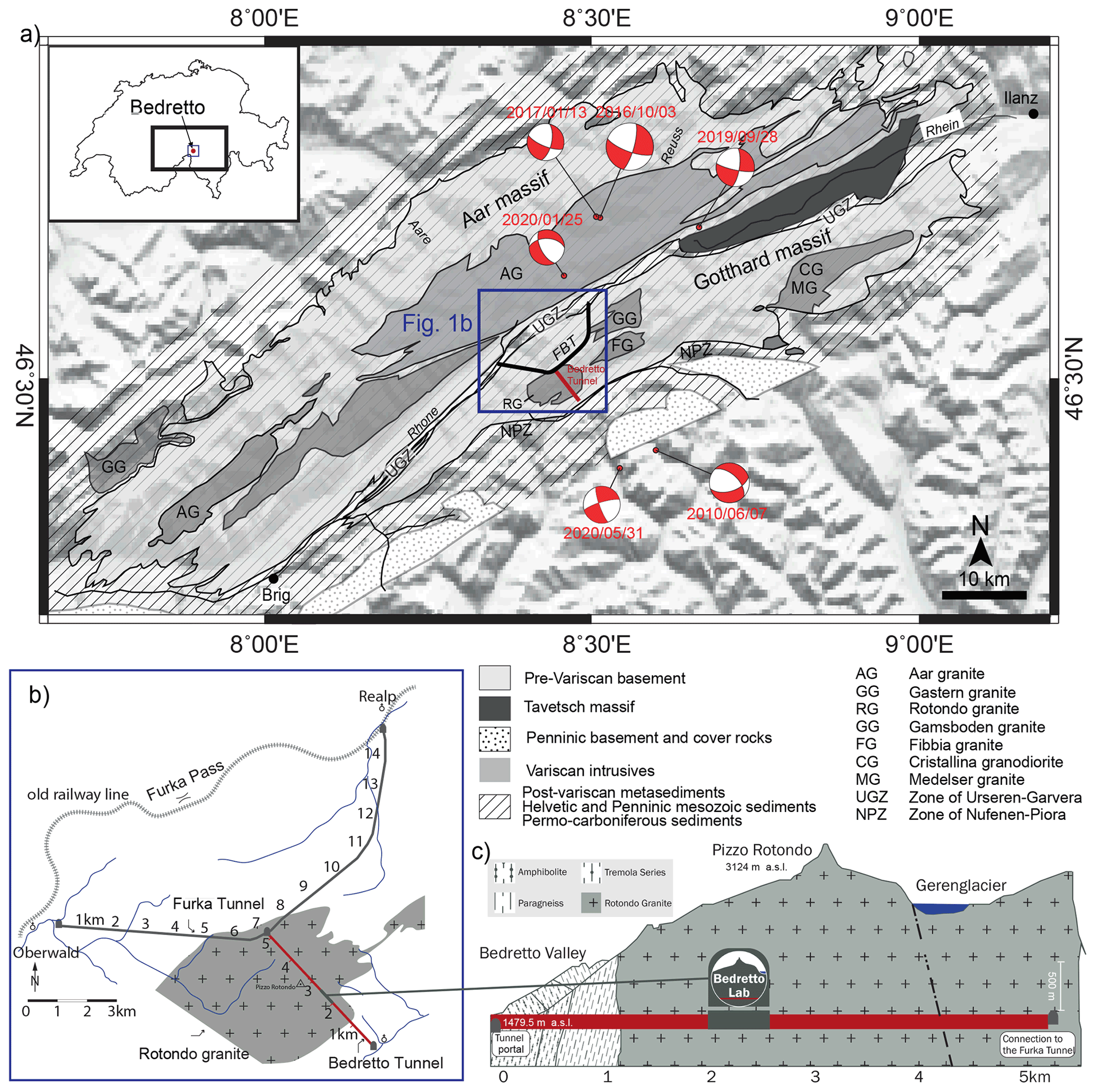
Figure 1(a) Integrated geological, topographical and seismological information near the Aar and Gotthard massifs surrounding the BedrettoLab (Keller and Schneider, 1982; adapted from Lützenkirchen and Loew, 2011, and Gischig et al., 2020). (b) Map view of the Bedretto Tunnel and the hosting Rotondo granite. (c) Cross-sectional view of the BedrettoLab with respect to the tunnel.
The horseshoe-shaped Bedretto Tunnel was excavated by drill-and-blast with a cross section of approximately 3 m by 3 m to host rails for mucking. In some sections, the tunnel was enlarged to allow mucking trains to pass by. Between TM2000–2100, the tunnel widens into a 6 m by 3 m (width by height) niche, which was selected to host the main part of the BedrettoLab and the first suite of multi-disciplinary rock mass characterizations.
Since its completion in 1982, the Bedretto Tunnel remained largely unlined and unpaved and was primarily used to facilitate ventilation and drainage of the Furka Base Tunnel. Therefore, the rock mass structural and hydrological conditions can be directly characterized, and the rock mass is accessible through relatively short boreholes. Detailed investigations carried out previously focused on groundwater flow systems (Lützenkirchen, 2002; Ofterdinger, 2001), brittle fault zone structures (Lützenkirchen, 2002), localized ductile deformation and geochronology (Rast, 2020), excavation-related rock mass failure (Alcaiìno Olivares, 2017; Ganye et al., 2020; Huber, 2004; Meier, 2017), and landslide structures (Vlasek, 2018). Since 2018, the Bedretto Tunnel has been made available by its owner, Matterhorn Gotthard Bahn (MGB), to ETH Zürich for long-term research, which prompted the establishment of the BedrettoLab.
2.1 Geologic and tectonic setting
From its south portal, the Bedretto Tunnel consecutively penetrates metamorphic terrains of the Helvetic domain, and in particular the Tremola series until TM434, the Prato series until TM1138 and the Rotondo granite until reaching its northwest terminus at the Furka Base Tunnel (Keller and Schneider, 1982) (Fig. 1c). The Tremola series is part of the Sasso zone, which is characterized by the predominance of chlorite-mica schists and gneisses (Steiger, 1962). The Prato series is characterized by amphibolites and layered biotite/quartz–feldspar gneisses in the southeast and mica and biotite gneisses and migmatites from TM635 towards the northwest (Rast, 2020). The granite body that hosts the majority of the Bedretto Tunnel is referred to as the Rotondo granite. The bulk composition of the Rotondo granite is primarily quartz (25 %–35 % by volume), alkali feldspar (microcline) (20 %–40 %), plagioclase (albite and oligoclase) (10 %–25 %) and biotite (3 %–8 %) (Hafner, 1958; Labhart, 2005). At some locations, trace amounts of mica, chlorite and garnet are encountered. The Rotondo granite is one of several magmatic bodies of the Gotthard massif (Rotondo, Gamsboden, Fibbia, Cristallina and Medelser). The intrusion of the Rotondo granite took place around 294 ± 1.1 Ma (Sergeev et al., 1995) in the late stages of the Variscan orogeny and is slightly younger than the Fibbia granite (299.4 ± 1.2 Ma) that intruded the Gotthard massif to the northeast (Keller et al., 1987; Schaltegger and Corfu, 1992). Ductile deformation with gneissic foliation within the Rotondo granite is generally concentrated around a few shear zones (Schneider, 1985). In some sections, a weak foliation is encountered (Lützenkirchen and Loew, 2011). The foliation is less pervasive than in the Fibbia granite (Schneider, 1985), where ductile shear zones are interpreted to have developed as a result of progressive Alpine deformation (Marquer, 1990). However, other studies suggest that the foliation in the older Fibbia granite developed during a late short-lived Variscan deformation phase that did not affect the younger Rotondo granite (Mercolli et al., 1994; Steiger and Guerrot, 1991).
The regional stress field near the Swiss Alps is not uniform and mainly affected by Alpine orogeny. The maximum horizontal stress (SHmax) azimuth is generally within the SE–NW quadrant (Heidbach et al., 2018; Kastrup et al., 2004). Based on focal mechanism solutions of more than 100 earthquakes within the region between 1960 and 2000, Kastrup et al. (2004) resolved a variation of the contemporary stress regime from a slight predominance of strike-slip in the Alpine foreland to a strong predominance of normal faulting in the high-altitude parts of the Alps. Based on the regional SHmax orientation pattern, a ∼ SE–NW azimuth of SHmax is expected around the Bedretto area, which would be sub-parallel to the Bedretto Tunnel. The predominance of a strike-slip stress regime and the transition towards normal faulting in high-altitude parts of the Alps implies that reverse faulting is unlikely in the study area.
2.2 Structural mapping
Medium- to large-scale fracture and fault zones (thickness ranging between sub-meters to tens of meters) are frequently visible on the tunnel walls. Fabrics and mineral assemblages of brittle–ductile fault zones in the northern section of the Bedretto Tunnel (between TM3500 and TM5218) have been previously mapped and analyzed in detail (Lützenkirchen, 2002; Lützenkirchen and Loew, 2011). A complementary structural mapping has recently been conducted between ∼ TM1140 (near the Rotondo granite contact) and TM2800 (Jordan, 2019). Overall, fractures and fault zones within the Rotondo granite are mostly dipping steeper than 50∘, and an absence of structures dipping to the east and south has been noted. Figure 2 inset shows that NE–SW- (tunnel-perpendicular) and N–S-striking structures dominate on stereonets. In addition, E–W and SE (tunnel-parallel) sets are mapped. The tunnel-perpendicular and E–W-striking sets are typically more prominent and associated with a higher degree of shearing, evidenced from core and outcrop observations. Structural mapping orientation results from the tunnel are consistent with those from surface scanline mapping in outcrops directly above the tunnel and on aerial orthophotos (Jordan, 2019). It is worth noting that the tunnel-parallel sets might be significantly undersampled (see Sect. 4.2 for expanded discussion).
The water inflow has also been qualitatively assessed for the fractures and fault zones between ∼ TM1140 and TM2800 (Jordan, 2019). The water inflows into the Bedretto Tunnel are primarily associated with fractures (i.e., no visible matrix porous media flow) and fault zones. We observed that a few highly conductive fault zones are responsible for the majority of the bulk water inflow in the tunnel. In general, the tunnel-perpendicular and E–W-striking sets are associated with higher inflows. These structures often contain fault cores with gouge and cataclasites. As we will outline later, these two sets of structures can potentially be active or be activated in a strike-slip and/or normal-faulting stress environment, with SHmax trending between E–W and SE–NW.
2.3 Preliminary in situ stress characterization
Along the Bedretto Tunnel, stress-induced rock failures (e.g., spalling and kinking) frequently occur on the sidewalls, primarily in tunnel sections where pre-existing fractures are hardly present. These spalling fractures do not appear to be directly induced by tunnel excavation damage due to blasting. The appearance of these stress-induced failures at the sidewalls suggests that the horizontal stress component perpendicular to the tunnel is smaller than the vertical stress. Therefore, a local reverse faulting stress regime (i.e., the minor principal stress S3=Sv) is unlikely. Accordingly, SHmax corresponds to either the intermediate principal stress S2 (i.e., normal faulting, S1=Sv) or the major principal stress S1 (i.e., strike slip, S2=Sv). Nonetheless, rotation of the stress tensor is possible due to local topography (Liu and Zoback, 1992; Meier, 2017). Given strong variations of the overburden above the Bedretto Tunnel (Fig. 1c), the topographic effect is in competition with the tectonics-controlled stress pattern to result in significant local stress variations along the tunnel. A previous study showed that the topographic effect is strong under a low overburden but diminishes significantly under a larger overburden (Meier, 2017).
Small-scale hydraulic fracturing tests, or “mini-fracs” (Haimson and Cornet, 2003), were conducted between December 2018 and July 2019 to obtain an estimation of the in situ stress field of the rock volume between TM1750 and TM2250 (Ma et al., 2019). The tests were performed in six short (30–40 m long) SB boreholes (“SB” denoting stress measurement borehole), avoiding major fault zones (Fig. 2). On borehole televiewer logs, the observed hydraulic fractures are steeply dipping, which generally agrees with the assumption that the overburden stress is larger than the horizontal stresses and approximates a principal stress direction. The inferred average direction of the maximum horizontal stress (SHmax) is approximately N100–110∘ E. The magnitude of the overburden or vertical stress (SV) is estimated by integrating the granite density of the overburden (≈ 1030 m), which is approximately 26.5 MPa. The measured Shmin magnitude is 14.6 ± 1.4 MPa, and the estimated SHmax is 25.4 ± 2.3 MPa (Bröker, 2019; Bröker and Ma, 2022). Acknowledging measurement uncertainty and local stress heterogeneity, the mini-frac tests indicate that the stress state in the vicinity of the BedrettoLab is transitional between normal and strike-slip faulting conditions (SV≥SHmax>Shmin). This is generally consistent with the expected regional stress state (Heidbach et al., 2018; Kastrup et al., 2004), although the stress ratio at the BedrettoLab differs significantly from that inverted from deep earthquakes in the region.
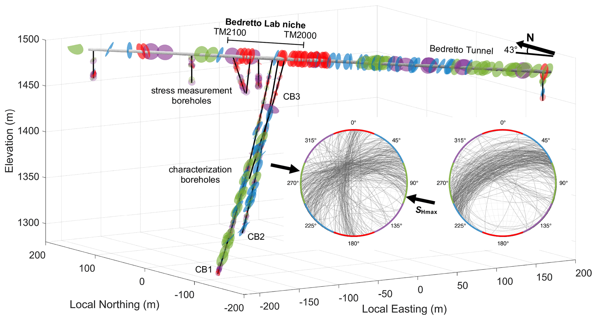
Figure 2Configuration of the CB1, 2 and 3 boreholes with respect to the Bedretto Tunnel. Fractures and fault zones, mapped along the tunnel and the boreholes, are colored with respect to their strikes. Stress measurement boreholes (SB) are also shown. Inset: stereonet of fractures and fault zones mapped along the tunnel (left) and the CB1, 2 and 3 boreholes (right) (only structures represented in the lower row of Fig. 7), respectively. The four fracture and fault sets are colored distinctly according to their strikes, which is also marked on the circumference of the stereonets.
From overnight pressure decay tests (the shut-in phase after the mini-frac re-opening cycle that typically lasts 13–15 h) in the SB borehole mini-frac intervals, the pore pressure (Pp) was measured and ranges between 2.0–5.6 MPa, considerably below the expected hydrostatic pressure (7–9 MPa, Vlasek, 2018). This reflects the impact of tunnel drainage and pressure drawdown that has been ongoing since the tunnel's excavation. Similar underpressured conditions have also been observed at distances of 60 m (4 MPa) and 90 m (5 MPa) from previous research boreholes located near the Bedretto Tunnel's NW terminus (Keith Evans, personal communication, 2018). Although such effects diminish further away from the tunnel, studies of similar underground laboratory settings suggest that cooling- and drainage-associated stress perturbations can still be present beyond 100 m from the tunnel wall (Fu et al., 2018). (Note: the ambient temperature inside the Bedretto Tunnel is ∼ 18 ∘C year-round.) The coupled effects of excavation damage zone, cooling and drainage certainly warrant cautious interpretation of the near-tunnel stress measurements (Evans et al., 2003).
In late 2019, three boreholes (CB1, 2 and 3; “CB” denotes characterization borehole) have been drilled between TM2000–2100 to enable a comprehensive characterization of the BedrettoLab rock mass volume. The lengths of sub-parallel boreholes range from ∼ 200 to 300 m and penetrate the rock mass at the tunnel's southwest side wall. Figures 2 and 3 present the three-dimensional view of the layout of these boreholes, in relation to the tunnel and the short SB boreholes. CB1, 2 and 3 boreholes were fully cored (with nominal borehole diameter of 97 mm and core size of approx. 63 mm). Technical details of these boreholes are compiled in Table 1. The cores facilitated a geological interpretation of the rock volume (Sect. 3.1). A suite of geophysical logging runs were conducted soon after the boreholes were drilled. Figure 4 presents a composite log of CB1 as an example. Geomechanical interpretation along the penetrated rock volume is complemented by discrete hydraulic fracturing stress measurements at selected depth intervals in CB1 (Sect. 3.2). Geophysical imaging was made available through ground-penetrating radar (GPR) in CB1, 2 and 3 boreholes to illuminate the complex geological structures (Sect. 3.3). A multi-packer system was installed in CB2 for hydraulic characterization within the complex structures (Sect. 3.4). We also present some of the laboratory testing results conducted on samples of the host Rotondo granite to date (Sect. 3.5).
Table 1List of characterization boreholes and measurements conducted therein.

Note: (1) all borehole azimuths are oriented N133∘ W. The nominal borehole diameter is based on the 97 mm coring bit; the actual borehole diameters slightly exceed 97 mm and vary with the coring scheme. (2) ATV/OTV: acoustic or optical televiewer; GPR: ground-penetrating radar; CAL: caliper; Cond.: electrical conductivity; DEV: deviation tool; FWS: full-waveform sonic; SGAM: spectral gamma; Temp.: temperature.
3.1 Geological characterization
The geologic characterization of the CB rock volume relies on the combination of core logging and acoustic or optical televiewer logs (ATV/OTV) to identify key structures. The characterized rock volume is composed of weakly deformed Rotondo granite protolith (i.e., weekly foliated), intersected by less frequently distributed, highly foliated ductile shear zones. The mylonitic ductile shear zones are quartz- and biotite-rich, and their contact with the protolith can be abrupt or gradual. The boreholes intersect a variety of structures, such as open fractures, filled fractures, the aforementioned mylonitic ductile shear zones, dikes and veins, and compositional foliation within the granite. The compilation of core description, structure typology and fault zone identification is shown in Fig. 5.
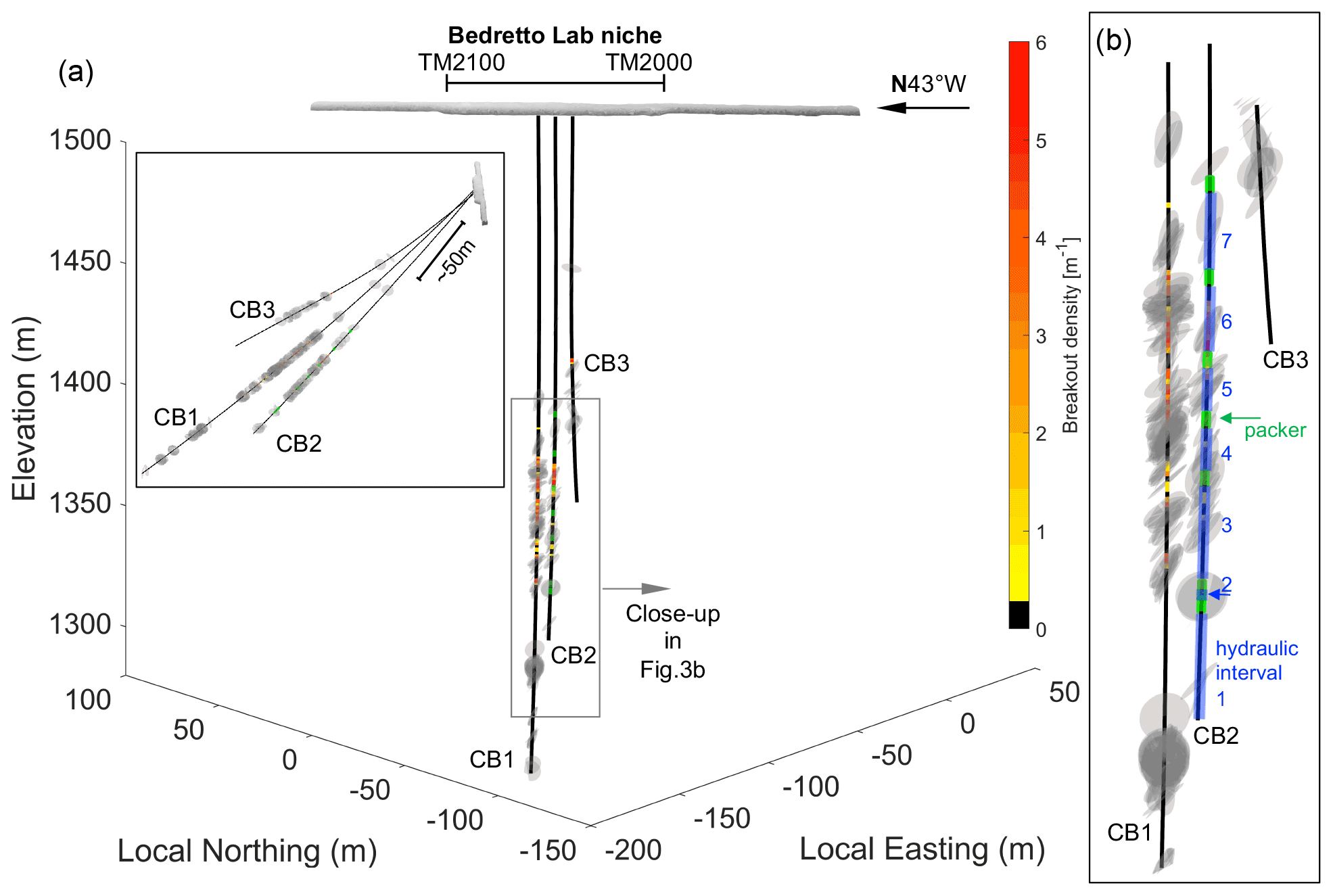
Figure 3Configuration of boreholes CB1, 2 and 3 and the mapped major fractures and fault zones therein. (a) Looking down approximately normal to the three boreholes. Inset shows the side view of the boreholes. (b) Close-up of the major fault zone interval. Note the breakout density along the CB borehole major fault zone and the multi-packer system (and the divided hydraulic intervals) installed in CB2 (see Table 2 for details).

Figure 4Integrated geophysical logs of borehole CB1: (a) gamma ray; (b) electrical conductivity; (c) temperature; (d) sonic compressional and shear wave velocities (Vp and Vs); (e) density of mapped fractures from televiewer logs.
Open fractures are clearly visible as traces in both ATV and OTV. In the cores, open fractures are identified by mineral precipitation on the fracture surfaces and in several instances vuggy porosity develops, likely due to hydrothermal alteration. The filled fractures are generally dark in color, commonly filled with biotite and/or quartz, and are discrete features less than 1–2 mm thick. Ductile shear zones occur in varying degrees of intensity. Some mylonite to ultra-mylonites have sub-millimeter foliations spanning a couple of meters in thickness or can occur as an abrupt strain localization feature of a couple to tens of centimeters in thickness. The thickness of quartz (commonly smoky grey) or aplitic dikes and veins ranges from less than 1 cm to about 20 cm. While compositional foliation in the granite protolith is generally not visible in cores or logs, in some cases the grains do align to form a weakly foliated texture at the core scale.
It appears that three distinct lithological units are present in the characterized rock volume, as revealed by the compiled core descriptions in CB1–3 (Fig. 5). Depending on the specific borehole, the first unit reaches to the measured depth (MD) of about 60 to 120 m. This unit is characterized by dikes (mostly aplitic) and isolated shear fractures. This shallow unit of the rock volume appears rather intact with less fractured and less deformed features. Deformation is significantly more intense in the middle unit, between 120 and 200 m MD, where the majority of fault zones are located. These fault zones are composed of multiple branches of anastomosing individual fault cores. After about 100 m of this highly fractured and highly deformed unit, or below ∼ 200 m MD, deformation seems to diminish, as fault zones are fewer and thinner than in the middle unit above. The fractures in this third unit are more discrete and singular as opposed to forming in swarms.
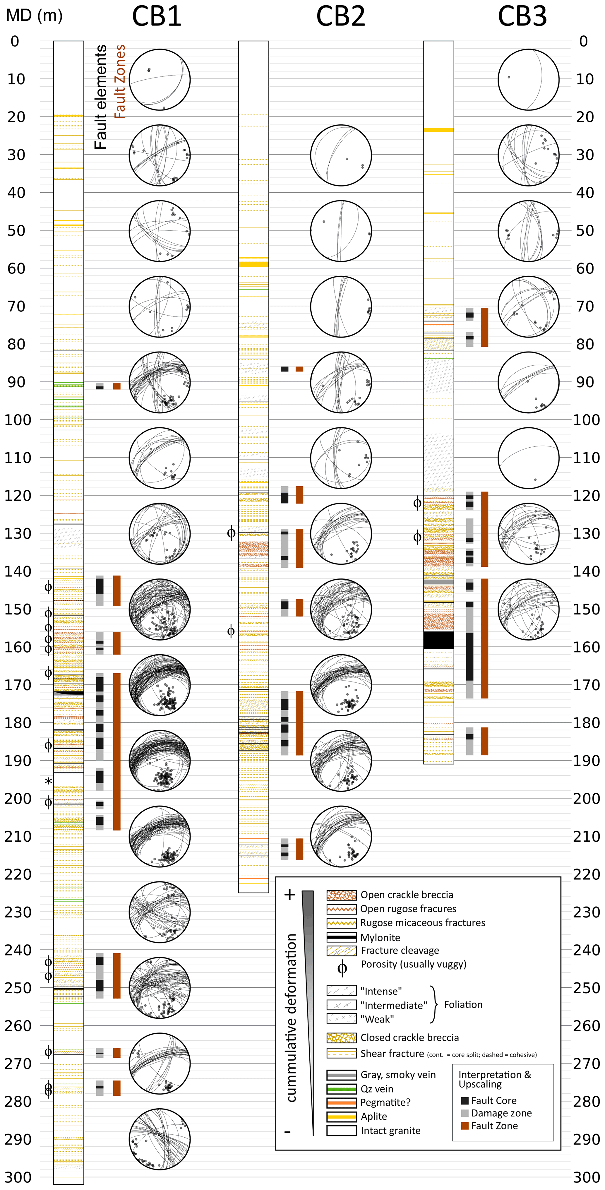
Figure 5Core description showing the geological designations and structural orientations (measured by the acoustic and optical televiewers, i.e., ATV/OTV).
Fault zones were identified in the recovered cores as the combination of several features that indicate a considerable concentration of deformation. Figure 6 shows an example from the middle fault zone unit intersected by CB1. Crackle breccias and mylonites, following the fault rock classification (Woodcock and Mort, 2008), are commonly identified. Fine-grained brittle fault rocks (e.g., fault gouges and cataclasites) are most probably present in the rock volume, but their poor consolidation precludes an efficient core recovery. Our observation shows fault zones composed of multiple fault core branches with overlapping damage zones and internal lenses of rock with little deformation. This configuration is close to the conceptual model of fault zones (Faulkner et al., 2003) and differs from the single fault core model (Chester et al., 1993).
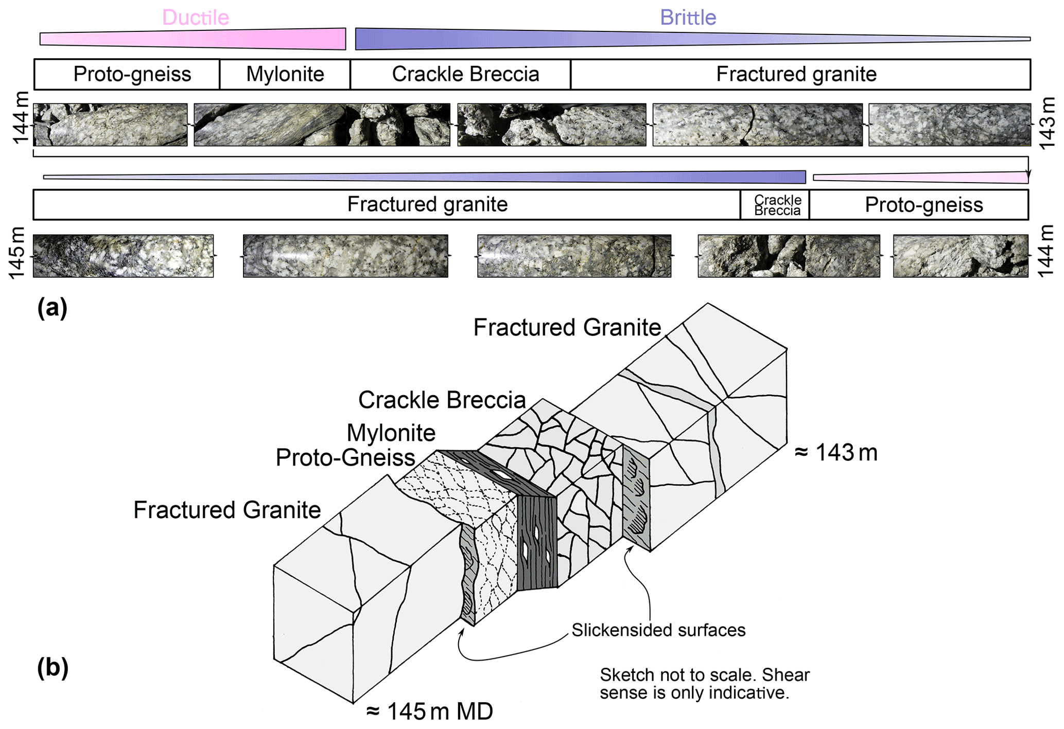
Figure 6(a) Core images, compositions and the structure of the major fault zone encountered in borehole CB1 (between 143–145 m measured depth). Ductile and brittle structures can be seen in close proximity to each other. Brittle structures are located at the boundaries of ductile features. (b) Schematics of the fault zone structure.
Figure 7 shows the orientations of each structure type. The most important structures in terms of cumulated deformation (lower row) trend almost exclusively NE–SW. The same pattern is shown when comparing structure orientations around fault zones with structures in between fault zones (Fig. 5). Near the fault zones, the distribution of orientations tends to be unimodal around the NE–SW direction (tunnel-perpendicular) while the rock volume in between fault zones also includes structures oriented N–S and NW–SE (tunnel-parallel).
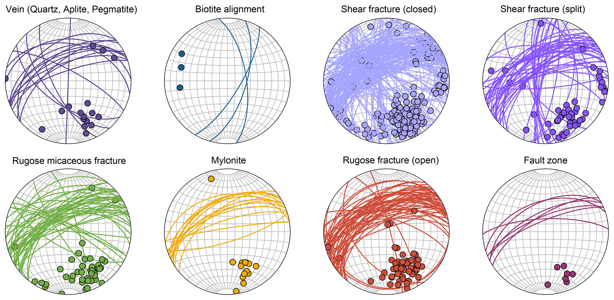
Figure 7Mapped geological structures by type. The upper row shows the orientation of structures that are mainly “closed” (based on visual examination of the cores). The lower row shows the orientations of structures with higher shear strain and can be perceived as “open”. Note the structures shown in the lower row are almost exclusively oriented NE–SW.
3.2 Geomechanical characterization
A few dedicated stress measurements were conducted at selected depth intervals in borehole CB1 via mini-frac tests. Mini-frac tests could not be conducted within the borehole measured depth (MD) of 150–250 m, as high fracture density and borehole enlargement or washouts prevented reliable packer seating and intact interval selection. The instantaneous shut-in pressures (ISIPs) of the mini-frac cycles lead to reliable estimates of the least principal stress (or presumably Shmin) (Fig. 8a). These Shmin values are mostly around the frictional limit imposed by a frictional coefficient of μ=0.6 and a hydrostatic pore pressure gradient. A frictional coefficient μ=0.6 is considered to be representative for granites at depth (Byerlee, 1978). Within a few borehole intervals (e.g., MD = 53, 113, 133 m), the Shmin magnitudes are noticeably higher than the rest. It is worth noting that the measured in situ pore pressure is substantially below hydrostatic pressure; therefore, the theoretically permitted lower bound of Shmin in this instance should be much below the expected values under the hydrostatic conditions.
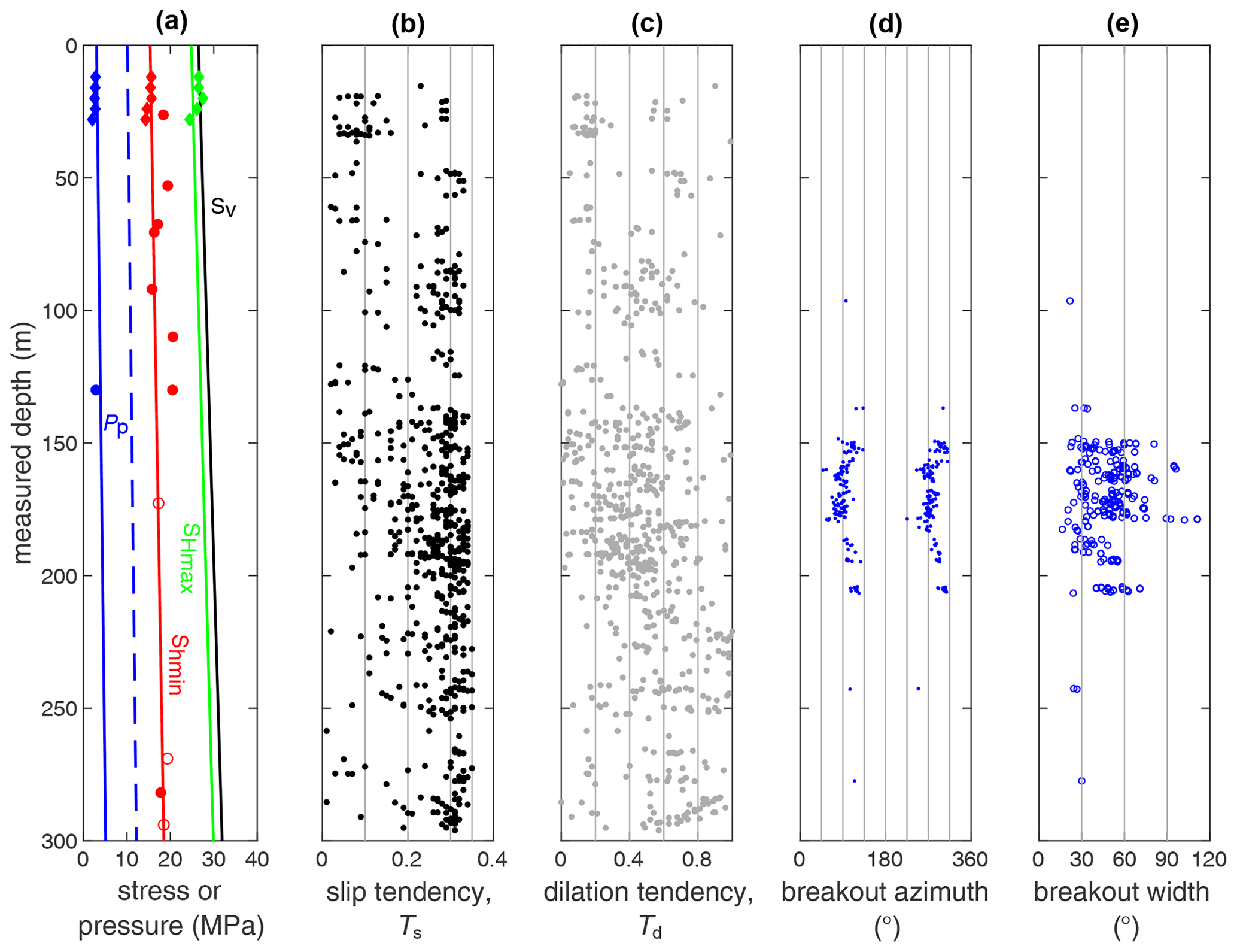
Figure 8Integrated geomechanical information of borehole CB1: (a) stress and pore pressure profiles (diamonds are from SB borehole data; circles are from CB1, while open circles are of uncertainty; dashed blue gradient represents hydrostatic pore pressure); (b) slip tendency (Ts) and (c) dilation tendency (Td) of all mapped structures (shown in Fig. 5); (d) breakout azimuths and (c) widths (0∘ refers to the high side of the borehole).
The Shmin values estimated from mini-fracs in CB1 are generally consistent with those obtained from the SB boreholes (Bröker, 2019; Bröker and Ma, 2022). The average Shmin values of SB borehole measurements are also depicted in Fig. 8a, mostly near the lower bounds of the measured values in CB1 borehole. The actual stress and pore pressure gradients based on the CB1 and SB borehole measurements facilitate the estimation of the slip tendency () and dilation tendency (Td= ) (Morris et al., 1996), where τ and σn are the shear stress and normal stress on the fracture or fault surface. The slip tendency Ts values associated with the CB1 fractures do not exceed 0.4, which is generally not considered critical under the typical crustal stress state.
A notable stress indicator is the occurrence of breakouts in all three CB boreholes (van Limborgh, 2020). These breakouts primarily developed within the broadly defined middle fault zone unit. Only a few breakouts were observed outside this unit. The depths and widths of the breakouts in CB1 are summarized in Fig. 8d, e. Looking downhole, the diametrically opposite breakout pairs are systematically located around both sides of the borehole, suggesting relative strength isotropy despite weak foliations. Within the middle fault zone unit, breakouts vary in width, depth and azimuth or disappear in some sections. The breakouts' azimuthal rotations in the immediate vicinity of individual fractures are likely associated with stress perturbation due to shear dislocation of fossil or active fractures or faults (Shamir and Zoback, 1992); the longer wavelength rotations spanning the entire fault zone unit plausibly reflect systematic stress variation associated with the fault zone. The breakouts rotate counter-clockwise (looking downhole with the top of the borehole referenced as north) by ∼ 50∘ between ∼ 145 and 175 m MD, i.e., the beginning to the middle of the fault zone unit, then rotate backwards by approximately the same extent until they terminate at the end of the fault zone unit (at ∼ 220 m MD).
3.3 Geophysical imaging
Geophysical imaging of the BedrettoLab rock volume consists of ground-penetrating radar (GPR) in both single-hole and cross-hole configurations. The sensitivity of electromagnetic waves is affected by different rock properties, namely the dielectric impedances between the host rock and faults/fractures. GPR surveys have been conducted in all three CB boreholes with antenna systems of various center frequencies (20, 100, 250, 500 and 1000 MHz) and varying spacings.
The premise of GPR single-hole reflection imaging is to delineate structures that provide a contrast in dielectric properties in the medium. In the BedrettoLab rock volume, this is primarily a contrast between fractures (filled by clay minerals and/or water) and the granitic host rock. Laboratory measurements on borehole cores reveal that the Rotondo granite has little to no variability in dielectric properties and is largely isotropic. The loss tangent (phase angle between the resistive and reactive components) of the dielectric constant is small, which facilitates large penetration depths. The relative dielectric permittivity of the host rock (εr=5.5) does not vary significantly over the applied frequency range. As a result, single-hole reflection imaging, where both transmitter and receiver antennas are in the same borehole, provides clean and repetitive data that can be used to extract geometric information about the major fault zones present in the characterized rock volume. For the detailed processing steps that we performed on the raw data, we refer to Shakas et al. (2020).
The electrically resistive granitic rock of the BedrettoLab is a pristine setting for GPR reflection imaging. Figure 9 shows the 100 MHz reflection survey for boreholes CB1, 2 and 3. Clear reflections arising from nearby boreholes, as well as from several (potentially) water-filled fractures and faults, were identified. The first major fault intersects the borehole CB1 at approximately 145 m MD, which is consistent with the ATV/OTV logging observations. This fault provides a strong reflector that is traced over several hundreds of meters. The observed thickness of the reflected structures on the GPR image correlates with their areas and hydraulic apertures. A more detailed study that combines GPR reflections and televiewer observations to delineate the geometry of the observed major fault can be found in Shakas et al. (2021). By comparing televiewer observations to near-borehole GPR effects, the latter study also suggests that the observed reflections are primarily due to water-filled (open) structures (faults and fractures) and not to mineral-filled (closed) structures. We further notice that the GPR reflections match well the assumed geometry of the major fault and can further introduce constraints on the fault geometry further away from the boreholes.
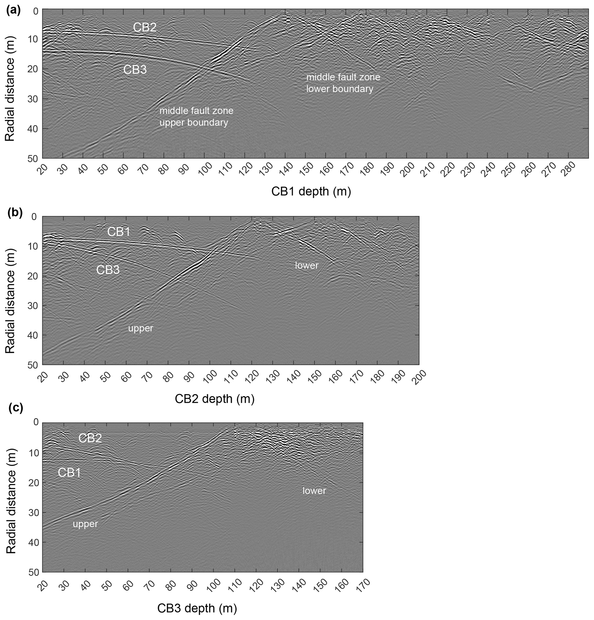
Figure 9Single-hole GPR reflection profiles (100 MHz) along (a) CB1, (b) CB2 and (c) CB3. From each borehole, the nearby boreholes are identified (and labeled) as prominent reflectors. The middle unit of the first major fault zone is clearly dominant in the figure. The fractured rock below this fault zone is characterized by higher reflectivity. Above the fault zone, some parabolic reflectors are seen that are likely attributed to borehole-perpendicular fractures.
The chevron type (V-shaped) pattern that the reflector (Fig. 9) exhibits is a known ambiguity of borehole GPR surveys. This artifact is introduced by projecting the fault or fracture plane that intersects the borehole in 3D onto 2D space (Olsson et al., 1985). To overcome this issue, Hediger (2020) performed the correlation between the structures inferred from GPR reflections and ATV/OTV data, in an effort to delineate the major fault zones and fractures. Furthermore, several diffractions can be seen in the upper volume. These are most probably due to water-filled fractures or faults that are sub-perpendicular to the borehole trajectory (Grasmueck et al., 2010).
3.4 Hydraulic characterization
Hydraulic tests were carried out in borehole CB1, 2 and 3 to characterize their transmissivity (Münger, 2020). The connectivity between different intervals or boreholes was also identified based on the measurable pressure response in one interval or borehole due to injection or production in another. Borehole CB1 and CB3 were closed at the borehole mouth (open-hole). In CB2, a system of multi-packers (each 1 m long) was used to effectively isolate six intervals (see Fig. 3b). The CB2 intervals were chosen based on the observed fracture or fault clusters from the core and logging observations (Table 2): individual fractures in intervals 1 and 2; frequent occurrence of fractures in intervals 3 and 4; and fault zones and fracture zones in intervals 5, 6 and 7. For hydraulic characterization, constant flow rate tests were carried out in CB1 and CB3 as well as in all six intervals in CB2. Before the main flow test in each interval, a short pulse test was carried out in the corresponding interval to have an initial estimate of the transmissivity of that interval, based on which the flow rate for the main test was calculated based on the infinitely acting radial flow assumption in such a way to have (ideally) a maximum of 1 MPa pressure change during the injection and production to minimize geomechanical effects influencing the transmissivity results. The duration of the flow test or recovery period was set so that the infinitely acting radial flow is observed for a 1.5 log cycle following the wellbore storage effect. Repeated tests were performed in intervals 4 and 7 in CB2. All test results, including the repeated measurements, are summarized in Table 2.
Table 2Single-hole hydraulic test results.
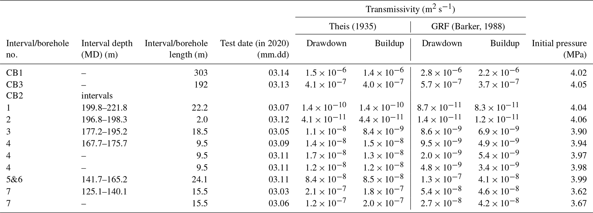
Note: (1) the packer between intervals 5 and 6 did not provide proper sealing, resulting in a direct hydraulic connection between the two intervals. Thus, the interconnected intervals 5 and 6 are considered a single interval, i.e., “interval 5&6”. (2) Pressure measurements were conducted at the tunnel floor. Thus, the hydrostatic heads at the (center of the) interval depth are subtracted from the reported pressure values. (3) The analysis of the transient pressure curves was carried out with the MATLAB Toolbox “hytool” (Renard, 2017). The tests were analyzed with two models, Theis (1935) and Generalized Radial Flow (GRF) (Barker, 1988). (4) The initial pressures of the boreholes/intervals were also determined with Horner (1951) plots and linear fitting.
The estimated transmissivities for different intervals and boreholes differ by several orders of magnitude. CB1 and CB3, each characterized along its full length, show the highest transmissivities (∼ and ∼ m2 s−1, respectively). The isolated intervals in CB2 and the open boreholes (CB1 and CB3) are assumed to be under steady-state pore pressure before the start of the flow tests. This assumption and therefore the estimated transmissivities of individual boreholes have to be treated with caution, since these long intervals, in particular the open holes, include several conductive structures with non-uniform pressure heads, which might cause some cross-flow between different structures within the same test interval. The isolated intervals in CB2 can be classified into three different groups based on their increasing transmissivities: (a) intervals 1 and 2; (b) intervals 3 and 4; and (c) intervals 5, 6 and 7. The estimated transmissivities in CB2 intervals are consistent with the geological observations. Since all three boreholes are sub-parallel, CB1 and CB3 are expected to encompass the majority of the fractures and faults included in intervals 1 to 7 in CB2. As expected, the transmissivity values of CB1 and CB3 are at least as high as the largest transmissivity observed within the intervals of CB2.
In order to identify major hydraulic flow pathways within the characterized rock volume, individual constant flow rate tests (drawdown and buildup) were conducted in CB1 and CB3 boreholes. The pressure response was monitored in the other borehole and in all CB2 intervals. The pressure response time is defined as the first notable pattern change in the pressure signal in the monitoring intervals and boreholes since the drawdown and buildup. The drawdown tests were executed with a constant extraction flow rate of 120 L h−1 in CB1 and 90 L h−1 in CB3, which resulted in a maximum pressure change of 0.2 and 0.4 MPa at the end of the flow period, respectively. Each drawdown test was followed by a buildup test (note: the characterization radius during the buildup test can be limited by the accuracy of the pressure gauge and the duration of prior drawdown interval and flow rate, Bourdarot, 1998). Based on the pressure decline curves, the characteristic response time between different boreholes and intervals during the drawdown tests are estimated (Table 3). The flow test in CB1 did not show any boundary effect at the end of the flow period, whereas CB3 showed signs of an infinite linear constant head boundary at the end of the flow period.
Table 3Characteristic pressure response time in the monitored boreholes/intervals during the drawdowns.
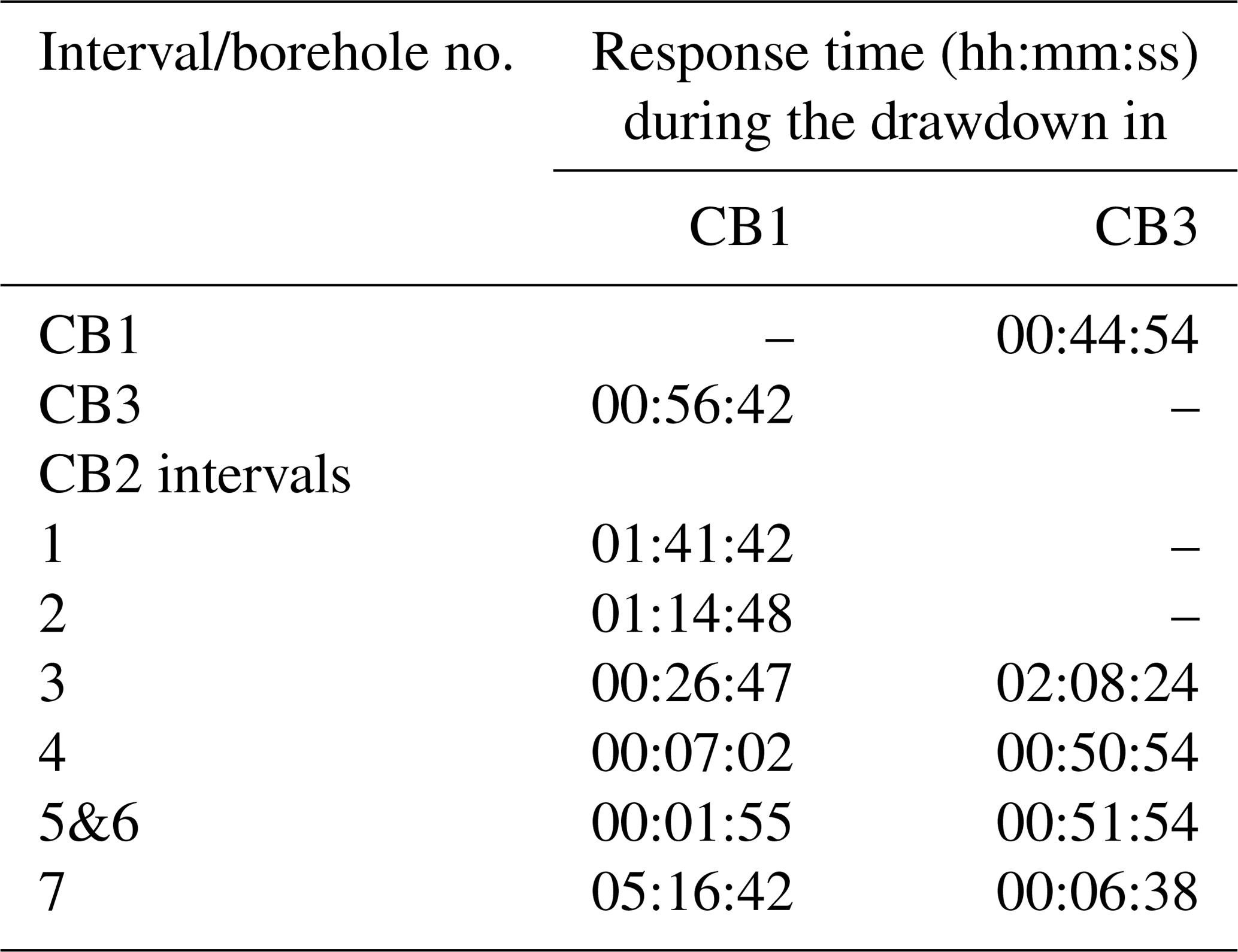
As shown in Fig. 10, during the drawdown test in CB1, all six CB2 intervals and the CB3 were hydraulically connected to CB1. However, during the drawdown test in CB3, the pressure response was only observed in CB2 intervals 3, 4, 5, 6 and 7 and in CB1. The results also show significant heterogeneity within the test volume. For example, interval 7 in CB2 shows strong hydraulic connectivity to CB3, with a response time of approximately 7 min, which contrasts the pressure response time of about 1 h during CB1 drawdown. Intervals 5 and 6, which are located immediately below interval 7 in CB2, show a very rapid hydraulic response to CB1 drawdown (less than 2 min), but a significantly delayed response to CB3 drawdown (∼ 50 min). Intervals 1 and 2 in CB2 are hydraulically connected with CB1, with a response time of approximately 100 min; however, no hydraulic response was observed after ∼ 180 min of drawdown in CB3. Given these observations, none of the intervals in CB2 seems to exhibit comparable hydraulic connectivity with CB1 and CB3, and a systematic pattern was not identified. Based on the results of the GPR surveys (Fig. 9), although the presence of a major cross-cutting structure that intersects all three boreholes (CB1-2-3) is evident from the survey, it is not fully comparable with the result from hydraulic tests. For example, the observed major structure from Fig. 9b intersects borehole CB2 at interval 7, whereas the results from hydraulic tests show strong hydraulic connection only between intervals 5 and 6 in CB2 with borehole CB1, but not with CB3. This can be mainly attributed to the strong heterogeneities in the reservoir volume, which causes strong anomalies in terms of hydraulic properties within short distances.
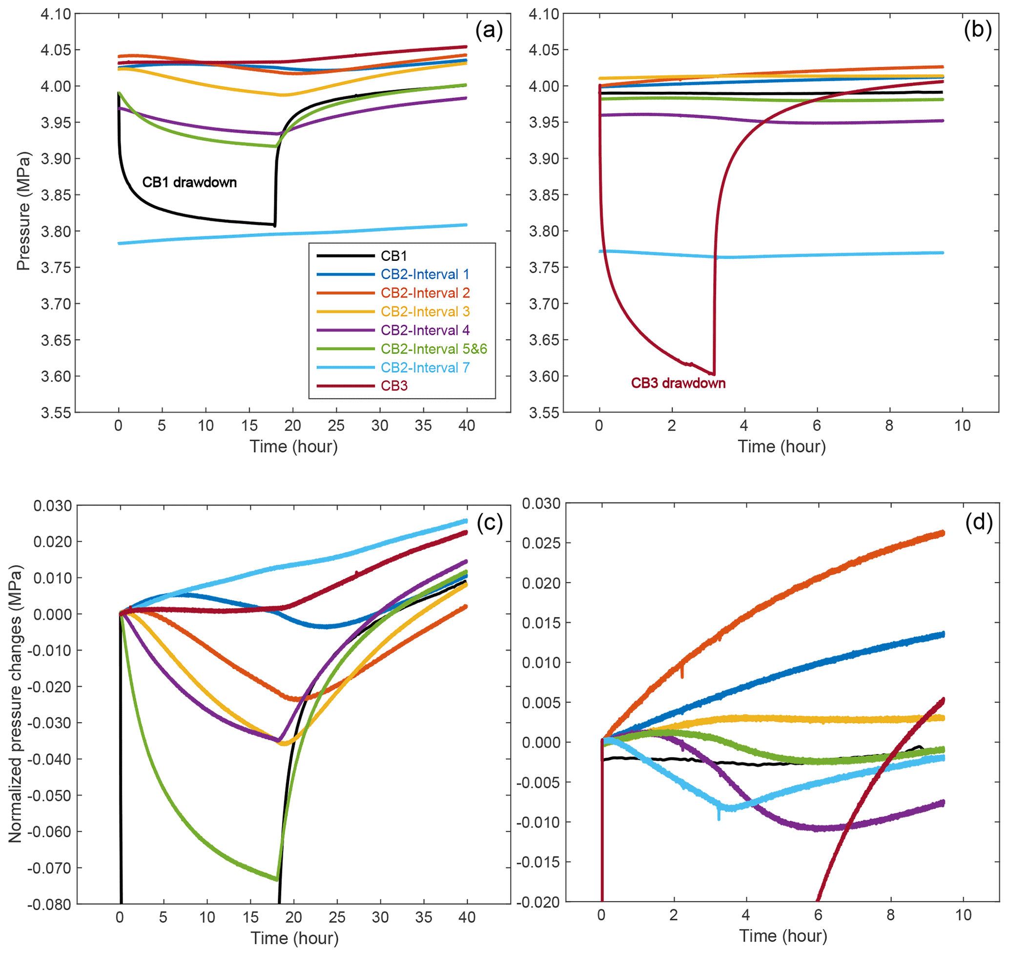
Figure 10The pressure response of boreholes/intervals to the drawdown in CB1 (a, c) and CB3 (b, d). The upper and lower row present the absolute and relative pressure (changes), respectively.
3.5 Laboratory petrophysical and mechanical characterization
Based on visual inspection, the majority of the Rotondo granite exposed at the tunnel wall appears to be homogeneous and isotropic. In the deeper parts of the CB boreholes, ductile shearing is apparent, suggesting physical anisotropy. Current laboratory benchtop characterizations (on various petrophysical and mechanical properties) were mostly focusing on the visually homogeneous core samples. The results suggest a low to moderate elastic anisotropy combined with considerable non-linearity of the elastic response. Table 4 gives a list of the physical and mechanical properties of the Rotondo granite in dry and water-saturated conditions. The details for these measurements are documented in David et al. (2020).
Table 4Selected physical properties of the Rotondo granite (measured under no confining stress).
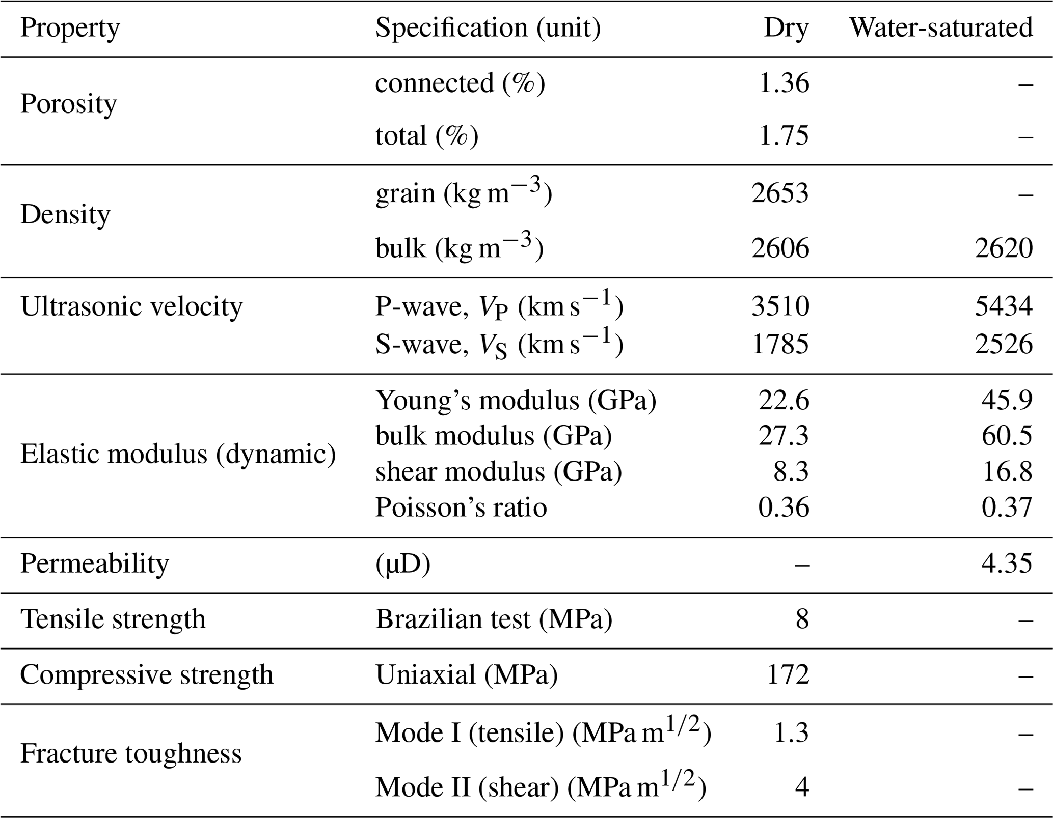
Despite its isotropic appearance and the absence of apparent fabric orientation, ultrasonic-wave velocity measurements indicate that the Rotondo granite is moderately anisotropic, with the P-wave anisotropy factors of about 6 % and 20 % for dry and water-saturated samples, respectively. A considerable surge in the ultrasonic-wave velocity by saturation (more than 50 %), significant non-linearity in the stress-strain relationship, high permeability and a considerably low P-wave quality factor of 4.9 (i.e., high attenuation level) all suggest a highly micro-cracked structure of the Rotondo granite.
The Rotondo granite features higher permeability when unconfined, as compared to other types of known granites. The permeability of Rotondo granite in the characterized Bedretto rock mass is roughly 10 times higher than that of Grimsel granite, and 100 times larger than that of Westerly granite (Brace et al., 1968; David et al., 2020; Wenning et al., 2018). The P-wave velocity is considerably dependent on the confinement pressure, suggesting a highly micro-cracked structure (David et al., 2020). If the high micro-crack density is characteristic of the pristine Rotondo granite in situ, a significant poroelastic response is expected given elevated pore pressures.
The multi-disciplinary characterization of the BedrettoLab conducted so far identified a rock volume that is both scientifically interesting and practically representative. The fractures and fault zones intersected by the CB boreholes inform us of the strong structural complexity and spatial heterogeneity at multiple scales. This is evidenced by the individual observations within and between several boreholes and different borehole intervals. Below we strive to provide an interdisciplinary interpretation of the characterization results, particularly in the context of the suitability of the rock mass as a test-bed to better understand the hydro-seismo-mechanical response of realistic crystalline basement rock reservoirs.
4.1 Heterogeneous rock mass, representative test volume
The characterized rock mass volume encompasses a multitude of features. One of the most prominent features is the middle unit composed of major fault zones and sandwiched by two comparatively more intact units. Although this middle fault zone unit is composed of several fault branches, it is found that these branches are generally sub-parallel to each other and form a cluster (Figs. 5 and 7). The whole cluster potentially traces back to the tunnel wall and coincides with the major fault zone observed between TM 1950–1993 (Castilla et al., 2020). Major fault zones of this scale seem to be repeatedly present along the Bedretto Tunnel for every few hundreds of meters (Schneider, 1985), and they are generally trending perpendicular to the tunnel (NE–SW) and/or E–W. Therefore, the presence of the middle fault zone unit, along with the sandwiching units, reasonably characterizes the rock mass that could be encountered within the BedrettoLab.
The sandwiching units above and below the middle fault zone unit are also considered to be characteristic of the Rotondo granite protolith. The two sandwiching units seem relatively homogeneous and share similar appearance, mineralogy (inferred from spectral gamma logs) and physical properties (e.g., wave velocities). Their properties are also consistent with those of the rock volume characterized by the SB boreholes scattered along the Bedretto Tunnel (Caspari et al., 2019; Greenwood et al., 2019). For example, the velocity profile along borehole CB1 (Fig. 4) shows a gradual increase in VP and VS with depth (from ∼ 5250 m s−1 and up, comparable to ∼ 5400 m s−1 from the SB borehole logs and the laboratory core measurements), despite the anomalies associated with the intersection of the major fault zones.
What accompanies the lithological unit variations are the stress variations along the CB boreholes. Although a more complete stress profiling is yet to be conducted, the azimuthal rotation of the breakouts across the middle fault zone unit informs us of the changes in stress orientations and magnitudes. The study to quantify why the breakouts only develop within the major fault zone but not in other parts of the CB boreholes nor any SB borehole is currently ongoing. Plausibly, low rock strength in the fault zone (substantially lower than the intact rock core) can promote breakout development. According to our scoping analysis, the breakout azimuth at ∼ 145 and 220 m MD in CB1 corresponds to a far-field SHmax azimuth between E–W and SE–NW (Zhang and Ma, 2021), which is generally consistent with the average value of ∼ N110∘ E measured from several SB borehole mini-fracs. The breakout rotation towards the middle of the major fault zone reaches ∼ 50∘, which requires substantial stress rotation and reduction in relative stress difference (or stress ratio). This could only be accommodated by the gradual changes in fault zone lithology and the associated rheological variations (Casey, 1980; Faulkner et al., 2003, 2010).
The stress orientation reversal towards the end of the middle fault zone unit indicates that it is likely to revert to the expected far-field stress condition that has been characterized. The local and global rotations of the breakouts suggest various scales of stress perturbations, which warrant further modeling. The stress variations simply manifest the heterogeneity and complexity of the rock volume. Such convoluted lithological and stress heterogeneities are characteristic of realistic fractured rock masses and should be considered when designing and conducting hydro-seismo-mechanical experiments therein.
4.2 Prevailing structures, hydraulically conductive features
The major structure sets in the BedrettoLab rock mass are all present in the characterized rock volume. There are four prevailing sets of fractures and faults identified along the Bedretto Tunnel (azimuth N317∘ E). All four sets of structures have been intersected by characterization boreholes CB1, 2 and 3 (azimuth N227∘ E). We are cognizant of potential undersampling of certain structures in each mapping campaign. For example, the tunnel-parallel sets might be under-mapped along the tunnel, and similarly for the NE–SW-striking sets along the CB boreholes. However, this does not seem to be the case for the CB boreholes (inset of Fig. 2), as there are abundant structures striking ∼ NE–SW (± 15∘), sub-parallel to or at acute angles with the borehole azimuth. This is attributed to the ∼ 45∘ inclination of these boreholes so that the undersampling of these steeply dipping structures is remedied to some extent. It appears that the prevailing sets of fractures and faults in the BedrettoLab are reasonably represented in the characterized rock mass volume, but a more conclusive characterization is certainly warranted potentially through the drilling of boreholes oriented differently from the existing CB boreholes.
As alluded to earlier, the NE–SW- and E–W-striking sets of fractures and fault zones appear to be the primary structures that are hydraulically conductive in the BedrettoLab rock volume. These structures have been identified from the tunnel walls, contributing to relatively higher inflow rates among other sets. This qualitative correlation is confirmed by several independent lines of evidence noted in the CB borehole characterization. Coinciding with these fracture and fault sets, appreciable anomalies have been identified along the thermal and electrical conductivity logging profiles (Fig. 4b, c); the core samples exhibit significantly higher degree of shearing; and strong reflections are shown on GPR images, indicating relatively wider hydraulic apertures and/or higher dielectric property. These observations all suggest that the NE–SW- and E–W-striking sets are the main hydraulically conductive conduits in the BedrettoLab rock volume.
It is worth noting that the NE–SW- and E–W-striking sets are more favorably oriented in the prevailing normal and/or strike-slip faulting regime. Taking the measured average of N100∘ E SHmax azimuth, steeply inclined structures forming acute angles with respect to SHmax are generally more susceptible to slip. Quantitatively, the calculated slip tendency shown in Fig. 8 indicates that the NE–SW- and E–W- striking sets are indeed associated with higher slip tendency. Although the absolute values of slip tendency (< 0.4) are below the empirical frictional limits (∼ 0.6) (Byerlee, 1978), the relative criticality between different structure sets seems to support the first-order control of the in situ stress.
It has been generally regarded that critically stressed fractures and faults are associated with hydraulic conductivity (Barton et al., 1995; Townend and Zoback, 2000), because the naturally occurring hydro-shearing processes enhance and maintain fracture permeability. The critically stressed fracture concept can plausibly explain the NE–SW- and E–W-striking sets being more hydraulically conductive, applicable to both the tunnel-mapping and CB borehole structures. Previous field observations supporting the critically stressed fracture concept (Barton et al., 1995; Rogers, 2003) were mainly conducted at scales of several-kilometer-long full-size boreholes so that this first-order relationship is not heavily affected by local stress variabilities that occur at smaller scales. While this might be the case for the tunnel-mapping structures, it is perhaps a tenuous justification in the case of the CB structures. As already shown, strong stress variations are evident along the CB boreholes, particularly around the fault zones. The local stress variations inevitably affect the slip tendency of individual fault branches. Given that the fault-perturbed in situ stress state becomes less anisotropic, the slip tendency is expected to decrease, weakening the critically stressed fracture concept. The associated stress changes around the fault zone further complicate the correlation between the stress criticality and fracture conductivity for individual fractures and faults. Nevertheless, it is important to take into account the corresponding scale where the stress variability is concerned (Ma et al., 2020a). The applicability of the critically stressed fracture concept to the particular case here certainly warrants further study.
Alternatively, stress-controlled hydraulic conductivity can be evaluated based on the dilation tendency (Morris et al., 1996). This concept was introduced for crustal rock masses at relatively shallow depths (e.g., < 1 km) (Mattila and Follin, 2019), for which variations of the normal stress on the fracture or fault exert significant control on its hydraulic aperture and consequently conductivity. The calculated dilation tendency profile along borehole CB1 (Fig. 8c) shows that the main conductive structures are subject to high normal stress, i.e., low dilation tendency. which makes it difficult to evaluate the applicability of the dilation concept. It is ambiguous to quantify the dilation tendency of tunnel-mapping structures, as the exact stress condition is unknown and subject to significant topographic variations.
Correlating stress with hydraulic conductivity assumes that the present stress state dominates. However, the high-conductivity feature of certain structure sets might have already developed under the paleo-stress condition. Although the stress condition has evolved, the high conductivity could still be sustained until the present day. If that is the case, distinguishing them from those structures naturally reactivated and hydraulically enhanced in geologically recent time would be challenging.
4.3 Complex, compartmentalized hydro-structures
Along the Bedretto Tunnel, recurring major fault zones serve as the main hydraulic conduits, channelizing fluid circulation in the rock mass. Since these fault zones are generally sub-parallel, it is unknown to what extent these main conduits are hydraulically connected. Preliminary hydrological and geochemical analysis indicates that water composition changes between these conduits (Bernard Brixel, personal communication, 2021), which suggests certain degrees of hydraulic compartmentalization of the whole rock mass along and across major structures. Such hydraulic compartmentalization also exists within the rock volume characterized by the CB boreholes. During the drilling phase, it was reported that abrupt increases in formation pore pressure and flow rate were associated with the penetration of the middle fault zone unit and branches therein (Meier, 2020).
According to our interdisciplinary observations, those fault zones in the BedrettoLab rock volume simultaneously act as the main hydraulic conduits along the fault planes and as impermeable layers across the fault planes. This is consistent with the general understanding of the fault structure in that the fault core is surrounded by damage zones (Chester et al., 1993; Faulkner et al., 2003). The fault core can be relatively impermeable for cross-flow but is able to maintain overpressure and appreciable flow therein (Faulkner et al., 2010). There was significant core loss and borehole enlargement when those fault zones were penetrated, so only a qualitative understanding of the fault structure was possible from examining cores and borehole televiewer logs (Figs. 5 and 6). On the other hand, GPR profiles allowed us to infer the physical contrast between the protolith and the fault zone rocks (Fig. 9). Strong reflections of the fault zones due to distinct water-bearing capacity clearly set themselves apart from the Rotondo granite, although recognizing the exact fault trace is challenging, due to the inherent ambiguity of the GPR interpretation and the complexity of the intersecting fault (zone) branches.
The complexity of the major fault zones results in compartmentalized hydro-structures. Hydraulic characterization in the CB rock volume revealed significant heterogeneity of hydraulic transmissivity (Table 2). Such heterogeneity is present both along individual boreholes and between boreholes, depicting complicated dominant flow paths within the rock volume. The hydraulic transmissivities differ by several orders of magnitude along multiple packed intervals of borehole CB2. This reflects the significant discrepancy of hydraulic property between several permeable fractures or fault zones segmented by the multi-packer system. An interesting observation is the asymmetric hydraulic response between both sides of CB2, i.e., a diametrically opposite behavior between the CB1-CB2 and CB3-CB2 connectivity. As suggested earlier, correlation of cores between the CB boreholes suggests that the major fault zone varies in thickness and features multiple laterally inconsistent branches (Figs. 5 and 6). This could explain the irregularity of spatial hydraulic compartmentalization and asymmetric hydraulic response within the rock volume. The local irregularity of structure geometry and the stress perturbation associated with the fault zones may also exert additional influence. A better understanding of the hydro-structures and the hydro-mechanical response within the rock volume requires carefully planned tracer tests and geophysical imaging, which is beyond the scope of this paper.
The BedrettoLab has recently been established in the Swiss Central Alps on the basis of the existing Bedretto Tunnel. It serves as an underground geoscience research laboratory and geoengineering test-bed. The BedrettoLab represents a new initiative for conducting meso-scale experiments on the crystalline rock masses and offers opportunities for international collaborations (e.g., site availability and data sharing). The BedrettoLab is now fully operational, and its main granitic rock mass volume has been extensively characterized via multi-disciplinary approaches. Combined geological, geomechanical, hydrogeological and geophysical methods were employed in several hectometer-scale boreholes to probe the in situ conditions and internal structures of the rock volume. A scientifically interesting and practically representative rock volume has been identified.
The characterized rock volume is approximately 100 m by 300 m by 100 m in size, off the southwest sidewall of the Bedretto Tunnel between TM2000–2100. The rock overburden there exceeds 1000 m, and the stress environment is dominated by normal and/or strike-slip faulting. The rock volume features three distinct units, with the middle fault zone sandwiched by two relatively intact units. The major fault zone appears to be a representative feature of the site, as similar structures repeat every several hundreds of meters along the Bedretto Tunnel. The fault zones are visible both on extracted cores and borehole imaging tools. The lithological variations across the fault zone manifest the complexity and heterogeneity of the rock volume. Significant variations of the hydrological and mechanical properties at various scales are evident. Pronounced stress rotations across the fault zone are observed. Compartmentalized hydrostructures have been identified, which seem to be segmented by the major fault zone and branches therein.
The characterized rock volume encompasses a multitude of complex features, and it approximates the representative scale and heterogeneity typically encountered in subsurface exploration and development of basement rocks. The rock volume will be further characterized and densely instrumented with tailored sensors. It will allow for in-depth studies of the hydro-seismo-mechanical response of fractured rock masses. The characterized rock volume will host a series of customized hydraulic stimulation experiments, serving as a test-bed for EGS reservoirs (referred to as the Bedretto Reservoir Project, BRP). Another rock volume further down the Bedretto Tunnel will be subsequently characterized and made available, enabling sophisticated fault reactivation experiments to study induced seismicity (referred to as the Bedretto Earthquake Project, BEP). These upcoming experiments are full of challenges and opportunities, with the hope to bridge the current knowledge gap and offer new insights.
All data used in this study are available through the BedrettoLab website (https://doi.org/10.3929/ethz-b-000527856, BedrettoLab Team, 2022) under “Publications” and then “Research Data”. Since this data set is of large quantity and an interdisciplinary nature, specific data requests can be made to the corresponding author and the project data manager, Rebecca Hochreutener (rebecca.hochreutener@erdw.ethz.ch).
All authors of this paper collectively contribute as a team of the BedrettoLab. The role of each team member is described here on the BedrettoLab website. Please use the following link: http://www.bedrettolab.ethz.ch/about/team/, last access: 25 January 2022. Specifically, MH, XM, HK, QW, AZ, RC and FS conducted the geological characterization. XM, FA, KB and VG conducted the geomechanics analysis. AO, KP, AS, LV and FB conducted the geophysical characterization. NGD and SL conducted the hydraulic characterization. MN organized the laboratory study. MH and QW oversaw the operational and logistical aspects of the experiments. HM, SW and DG supervised the project. All co-authors contributed to the writing of the paper.
The contact author has declared that neither they nor their co-authors have any competing interests.
Publisher's note: Copernicus Publications remains neutral with regard to jurisdictional claims in published maps and institutional affiliations.
The Bedretto Underground Laboratory for Geosciences and Geoenergy is a research infrastructure of ETH Zürich in the Department of Earth Sciences. The construction was financed by ETH Zürich and by the Werner Siemens-Stiftung. The Bedretto Tunnel is property of the Matterhorn Gotthard Bahnen (MGB). Help from Simone Zaugg and Shihuai Zhang with figure editing is greatly appreciated.
The BedrettoLab experiments are funded by the Swiss Federal Office of Energy (SFOE) (project VALTER), by the EU Horizon 2020 (project DESTRESS), by the EU initiative Geothermica – EraNet (projects ZoDrEx and SPINE), the Werner Siemens-Stiftung (project MISS) and by ERC (project SyG FEAR).
This paper was edited by David Healy and reviewed by Pär Grahm and one anonymous referee.
Achtziger-Zupančič, P., Loew, S., and Mariéthoz, G.: A new global database to improve predictions of permeability distribution in crystalline rocks at site scale, J. Geophys. Res.-Sol. Ea., 122, 3513–3539, https://doi.org/10.1002/2017JB014106, 2017.
Alcaiìno Olivares, R.: Assessing the influence of the environmental conditions on the fracture growth in the bedretto tunnel – Switzerland, University of Leeds, 2017.
Amann, F., Gischig, V., Evans, K., Doetsch, J., Jalali, R., Valley, B., Krietsch, H., Dutler, N., Villiger, L., Brixel, B., Klepikova, M., Kittilä, A., Madonna, C., Wiemer, S., Saar, M. O., Loew, S., Driesner, T., Maurer, H., and Giardini, D.: The seismo-hydromechanical behavior during deep geothermal reservoir stimulations: open questions tackled in a decameter-scale in situ stimulation experiment, Solid Earth, 9, 115–137, https://doi.org/10.5194/se-9-115-2018, 2018.
Barker, J. A.: A generalized radial flow model for hydraulic tests in fractured rock, Water Resour. Res., 24, 1796–1804, https://doi.org/10.1029/WR024I010P01796, 1988.
Barton, C. A., Zoback, M. D., and Moos, D.: Fluid flow along potentially active faults in crystalline rock, Geology, 23, 683–686, https://doi.org/10.1130/0091-7613(1995)023<0683:FFAPAF>2.3.CO;2, 1995.
BedrettoLab Team: Data Collection for the Bedretto Reservoir Project (BRP), ETH Zürich Library Research-Collection [data set], https://doi.org/10.3929/ethz-b-000527856, 2022.
Bourdarot, G.: Well testing: Interpretation methods, Editions Technip, 337 pp., ISBN 2710807386, 9782710807384, 1998.
Brace, W. F., Walsh, J. B., and Frangos, W. T.: Permeability of granite under high pressure, J. Geophys. Res., 73, 2225–2236, https://doi.org/10.1029/JB073I006P02225, 1968.
Bröker, K.: In-situ stress and rock mass characterization via mini-frac tests at the Bedretto Underground Laboratory, MSc thesis, ETH Zurich, https://doi.org/10.3929/ethz-b-000445278, 2019.
Bröker, K. and Ma, X.: Estimating the Least Principal Stress in a Granitic Rock Mass: Systematic Mini-Frac Tests and Elaborated Pressure Transient Analysis, Rock Mech. Rock Eng., https://doi.org/10.1007/s00603-021-02743-1, 2022.
Byerlee, J.: Friction of Rocks, in: Rock Friction and Earthquake Prediction, edited by: Byerlee, J. D. and Wyss, M., Birkhäuser Basel, 615–626, https://doi.org/10.1007/978-3-0348-7182-2_4, 1978.
Casey, M.: Mechanics of shear zones in isotropic dilatant materials, J. Struct. Geol., 2, 143–147, https://doi.org/10.1016/0191-8141(80)90044-9, 1980.
Caspari, E., Greenwood, A., Baron, L., and Holliger, K.: Wireline logging of Bedretto stress measurement boreholes – preliminary results, in: SCCER-SoE Science Report 2019, 2019.
Castilla, R., Krietsch, H., Jordan, D., Ma, X., Serbeto, F., Shakas, A., Guntli, P., Bröker, K., Löw, S., Hertrich, M., Bethmann, F., and Meier, P.: Conceptual Geological Model of the Bedretto Underground Laboratory for Geoenergies, European Association of Geoscientists & Engineers, Conference Proceedings, 82nd EAGE Annual Conference & Exhibition, October 2021, Vol. 2021, 1–5, https://doi.org/10.3997/2214-4609.202011912, 2020.
Chester, F. M., Evans, J. P., and Biegel, R. L.: Internal structure and weakening mechanisms of the San Andreas Fault, J. Geophys. Res., 98, 771–786, https://doi.org/10.1029/92JB01866, 1993.
Clauser, C.: Permeability of crystalline rocks, Eos, Trans. Am. Geophys. Union, 73, 233–238, https://doi.org/10.1029/91EO00190, 1992.
Cornet, F. H.: Earthquakes induced by fluid injections, Science, 348, 1204–1205, https://doi.org/10.1126/science.aab3820, 2015.
David, C., Nejati, M., and Geremia, D.: On petrophysical and geomechanical properties of Bedretto Granite, MSc thesis, ETH Zurich, https://doi.org/10.3929/ethz-b-000428267, 2020.
Ellsworth, W. L.: Injection-Induced Earthquakes, Science, 341, 1225942, https://doi.org/10.1126/SCIENCE.1225942, 2013.
Elsworth, D., Spiers, C. J., and Niemeijer, A. R.: Understanding induced seismicity, Science, 354, 1380–1381, https://doi.org/10.1126/science.aal2584, 2016.
Evans, K., Dahlø, T., and Roti, J.-A.: Mechanisms of Pore Pressure-stress Coupling which Can Adversely Affect Stress Measurements Conducted in Deep Tunnels, Pure Appl. Geophys., 160, 1087–1102, https://doi.org/10.1007/PL00012562, 2003.
Faulkner, D. R., Lewis, A. C., and Rutter, E. H.: On the internal structure and mechanics of large strike-slip fault zones: field observations of the Carboneras fault in southeastern Spain, Tectonophysics, 367, 235–251, https://doi.org/10.1016/S0040-1951(03)00134-3, 2003.
Faulkner, D. R., Jackson, C. A. L., Lunn, R. J., Schlische, R. W., Shipton, Z. K., Wibberley, C. A. J., and Withjack, M. O.: A review of recent developments concerning the structure, mechanics and fluid flow properties of fault zones, J. Struct. Geol., 32, 1557–1575, https://doi.org/10.1016/J.JSG.2010.06.009, 2010.
Fu, P., White, M. D., Morris, J. P., Kneafsey, T. J., and Collab Team, E.: Predicting Hydraulic Fracture Trajectory Under the Influence of a Mine Drift in EGS Collab Experiment I, 43rd Workshop on Geothermal Reservoir Engineering, 12–14 February 2018, Stanford, CA, 1–11, 2018.
Fu, P., Schoenball, M., Ajo-Franklin, J. B., Chai, C., Maceira, M., Morris, J. P., Wu, H., Knox, H., Schwering, P. C., White, M. D., Burghardt, J. A., Strickland, C. E., Johnson, T. C., Vermeul, V. R., Sprinkle, P., Roberts, B., Ulrich, C., Guglielmi, Y., Cook, P. J., Dobson, P. F., Wood, T., Frash, L. P., Huang, L., Ingraham, M. D., Pope, J. S., Smith, M. M., Neupane, G., Doe, T. W., Roggenthen, W. M., Horne, R., Singh, A., Zoback, M. D., Wang, H., Condon, K., Ghassemi, A., Chen, H., McClure, M. W., Vandine, G., Blankenship, D., Kneafsey, T. J., and Team, E. C.: Close Observation of Hydraulic Fracturing at EGS Collab Experiment 1: Fracture Trajectory, Microseismic Interpretations, and the Role of Natural Fractures, J. Geophys. Res-Sol. Ea., 126, e2020JB020840, https://doi.org/10.1029/2020JB020840, 2021.
Ganye, J. A., Alcaino-Olivares, R., Perras, M. A., and Leith, K.: Back analysis to determine the stress state around the Bedretto Adit, Switzerland, ISRM Int. Symp.-EUROCK 2020, June 2020, ISRM-EUROCK-2020-029, 2020.
Giardini, D.: Geothermal quake risks must be faced, Nature, 462, 848–849, https://doi.org/10.1038/462848a, 2009.
Gischig, V. S., Giardini, D., Amann, F., Hertrich, M., Krietsch, H., Loew, S., Maurer, H., Villiger, L., Wiemer, S., Bethmann, F., Brixel, B., Doetsch, J., Doonechaly, N. G., Driesner, T., Dutler, N., Evans, K. F., Jalali, M., Jordan, D., Kittilä, A., Ma, X., Meier, P., Nejati, M., Obermann, A., Plenkers, K., Saar, M. O., Shakas, A., and Valley, B.: Hydraulic stimulation and fluid circulation experiments in underground laboratories: Stepping up the scale towards engineered geothermal systems, Geomech. Energ. Environ., 24, 100175, https://doi.org/10.1016/j.gete.2019.100175, 2020.
Goodman, R. E.: Introduction to rock mechanics, Wiley, 562 pp., ISBNs 10 0471812005, 13 978-0471812005, 1989.
Grasmueck, M., Coll, M., Eberli, G. P., and Pomar, K.: Diffraction imaging of vertical fractures and karst with full-resolution 3D GPR, cassis quarry, France, Conference Proceedings, 72nd EAGE Conference and Exhibition incorporating SPE EUROPEC 2010, June 2010, cp-161-00249, European Association of Geoscientists & Engineers, 2043–2047, https://doi.org/10.3997/2214-4609.201400841, 2010.
Greenwood, A., Caspari, E., Baron, L., and Holliger, K.: Borehole radar and full waveform sonic measurements of the Bedretto stress-measurement boreholes, in: SCCER-SoE Science Report 2019, 2019.
Hafner, S.: Petrographie des südwestlichen Gotthardmassivs zwischen St. Gotthardpass und Nufenenpass, ETH Zürich, Zürich, https://doi.org/10.3929/ethz-a-000097546, 1958.
Haimson, B. C. and Cornet, F. H.: ISRM Suggested Methods for rock stress estimation – Part 3: hydraulic fracturing (HF) and/or hydraulic testing of pre-existing fractures (HTPF), Int. J. Rock Mech. Min. Sci., 40, 1011–1020, https://doi.org/10.1016/j.ijrmms.2003.08.002, 2003.
Hediger, R.: 3D geological model of a shear zone conditioned on geophysical data and geological observations, ETH Zurich, https://doi.org/10.3929/ethz-b-000455004, 2020.
Heidbach, O., Rajabi, M., Cui, X., Fuchs, K., Müller, B., Reinecker, J., Reiter, K., Tingay, M., Wenzel, F., Xie, F., Ziegler, M. O., Zoback, M.-L., and Zoback, M.: The World Stress Map database release 2016: Crustal stress pattern across scales, Tectonophysics, 744, 484–498, https://doi.org/10.1016/j.tecto.2018.07.007, 2018.
Hertrich, M., Brixel, B., Broeker, K., Driesner, T., Gholizadeh, N., Giardini, D., Jordan, D., Krietsch, H., Loew, S., Ma, X., Maurer, H., Nejati, M., Plenkers, K., Rast, M., Saar, M., Shakas, A., van Limborgh, R., Villiger, L., Wenning, Q. C., Ciardo, F., Kaestli, P., Obermann, A., Rinaldi, A. P., Wiemer, S., Zappone, A., Bethmann, F., Castilla, R., Christe, F., Dyer, B., Karvounis, D., Meier, P., Serbeto, F., Amann, F., Gischig, V., and Valley, B.: Characterization, Hydraulic Stimulation, and Fluid Circulation Experiments in the Bedretto Underground Laboratory for Geosciences and Geoenergies, 55th U.S. Rock Mechanics/Geomechanics Symposium, Virtual, June 2021, ARMA-2021-1895, 2021.
Horner, D. R.: Pressure Build-up in Wells, 3rd World Petroleum Congress, The Hague, the Netherlands, 28 May 1951, 1951.
Huber, B.: Stress-induced Fractures in the Deep-seated Bedretto Tunnel: Their Geological and Geomechanical Reasons, ETH Zürich, 2004.
Ingebritsen, S. E. and Manning, C. E.: Permeability of the continental crust: dynamic variations inferred from seismicity and metamorphism, Geofluids, 10, 193–205, https://doi.org/10.1111/J.1468-8123.2010.00278.X, 2010.
Ingraham, M. D.: Introduction to the Special Issue: Deep Underground Laboratories II (USA), American Rock Mechanics Association, ARMA Lett., 1–2, 2021.
Jaeger, J. C., Cook, N. G. W., and Zimmerman, R.: Fundamentals of Rock Mechanics, Wiley, Fundamentals of Rock Mechanics, 4th Edn., 488 pp., ISBN 978-0-632-05759-7, 2007.
Jordan, D.: Geological Characterization of the Bedretto Underground Laboratory for Geoenergies, MSc thesis, ETH Zurich, Geological Institute, https://doi.org/10.3929/ethz-b-000379305, 2019.
Jordan, T., Fulton, P., Tester, J., Bruhn, D., Asanuma, H., Harms, U., Wang, C., Schmitt, D., Vardon, P. J., Hofmann, H., Pasquini, T., Smith, J., and the workshop participants: Borehole research in New York State can advance utilization of low-enthalpy geothermal energy, management of potential risks, and understanding of deep sedimentary and crystalline geologic systems, Sci. Dril., 28, 75–91, https://doi.org/10.5194/sd-28-75-2020, 2020.
Kastrup, U., Zoback, M. L., Deichmann, N., Evans, K. F., Giardini, D., and Michael, A. J.: Stress field variations in the Swiss Alps and the northern Alpine foreland derived from inversion of fault plane solutions, J. Geophys. Res.-Earth, 109, B01402, https://doi.org/10.1029/2003jb002550, 2004.
Keller, F. and Schneider, T. R.: Geologie und Geotechnik, Schweizer Ing. Archit., 24, 512–520, 1982.
Keller, F., Wanner, H., and Schneider, T. R.: Geologischer Schlussbericht Gotthard-Strassentunnel, Beiträge zur Geologie der Schweiz, Geotech. Ser., 70, 1987.
Krietsch, H., S. Gischig, V., Doetsch, J., F. Evans, K., Villiger, L., Jalali, M., Amann, F., and Löw, S.: Hydromechanical processes and their influence on the stimulation effected volume: Observations from a decameter-scale hydraulic stimulation project, Solid Earth, 11, 1699–1729, https://doi.org/10.5194/se-11-1699-2020, 2020.
Labhart, T.: Erläuterungen Zum Geologischen Atlas Des Schweiz 1:25 000, Val Bedretto, Atlasblatt, 68, 2005.
Liu, L. and Zoback, M. D.: The effect of topography on the state of stress in the crust: application to the site of the Cajon Pass Scientific Drilling Project, J. Geophys. Res., 97, 5095–5108, https://doi.org/10.1029/91jb01355, 1992.
Lützenkirchen, V.: Structural Geology and Hydrogeology of Brittle Fault Zones in the Central and Eastern Gotthard Massif, PhD thesis, Switzerland, ETH Zurich, 247 pp., https://doi.org/10.3929/ethz-a-004522949, 2002.
Lützenkirchen, V. and Loew, S.: Late Alpine brittle faulting in the Rotondo granite (Switzerland): Deformation mechanisms and fault evolution, Swiss J. Geosci., 104, 31–54, https://doi.org/10.1007/s00015-010-0050-0, 2011.
Ma, X.: Introduction to the Special Issue: Deep Underground Laboratories (DUL), American Rock Mechanics Association, ARMA Lett., 1–2, 2021.
Ma, X., Saar, M. O., and Fan, L.-S.: Coulomb criterion – bounding crustal stress limit and intact rock failure: Perspectives, Powder Technol., 374, 106–110, https://doi.org/10.1016/j.powtec.2020.07.044, 2020a.
Ma, X., Gholizadeh Doonechaly, N., Hertrich, M., Gischig, V., and Klee, G.: Preliminary in situ stress and fractures characterization in the Bedretto Underground Laboratory, Swiss Alps: implications on hydraulic stimulation, 1559–1567, 2019.
Manga, M., Beresnev, I., Brodsky, E. E., Elkhoury, J. E., Elsworth, D., Ingebritsen, S. E., Mays, D. C., and Wang, C.-Y.: Changes in permeability caused by transient stresses: Field observations, experiments, and mechanisms, Rev. Geophys., 50, RG2004, https://doi.org/10.1029/2011RG000382, 2012.
Marquer, D.: Structures et déformation alpine dans les granités hercyniens du massif du Gothard (Alpes centrales suisses), Eclogae Geol. Helv., 83, 77–97, 1990.
Mattila, J. and Follin, S.: Does In Situ State of Stress Affect Fracture Flow in Crystalline Settings?, J. Geophys. Res.-Sol. Ea., 124, 5241–5253, https://doi.org/10.1029/2018JB016791, 2019.
Meier, M.: Geological characterisation of an underground research facility in the Bedretto tunnel, BSc thesis, ETH Zurich, Zurich, https://doi.org/10.3929/ethz-b-000334001, 2017.
Meier, M.: Heat Dilution Testing in Deep Underground Excavations, MSc thesis, ETH Zürich, https://doi.org/10.3929/ETHZ-B-000447153, 2020.
Mercolli, I., Biino, G. G., and Abrecht, J.: The lithostratigraphy of the pre-Mesozoic basement of the Gotthard Massif: a review, Schweizerische Mineral. Petrogr. Mitteilungen, 74, 29–40, 1994.
Morris, A., Ferrill, D. A., and Henderson, D. B.: Slip-tendency analysis and fault reactivation, Geology, 24, 275–278, https://doi.org/10.1130/0091-7613(1996)024<0275:STAAFR>2.3.CO;2, 1996.
Münger, A.: Hydraulic Backbone of CB1 to CB3 Boreholes in the Bedretto Underground Lab, MSc thesis, ETH Zürich, https://doi.org/10.3929/ethz-b-000469250, 2020.
NRC: Rock Fractures and Fluid Flow: Contemporary Understanding and Applications, The National Academies Press, Washington, DC, https://doi.org/10.17226/2309, 1996.
Ofterdinger, U. S.: Ground water flow systems in the Rotondo Granite, Central Alps (Switzerland), ETH Zürich, https://doi.org/10.3929/ethz-a-004218089, 2001.
Olsson, O., Falk, L., Forslund, O., Lundmark, L., and Sandberg, E.: Investigations of Fracture Zones in Crystalline Rock by Borehole Radar, MRS Online Proc. Libr., 50, 145–154, https://doi.org/10.1557/PROC-50-145, 1985.
Perras, M. A. and Diederichs, M. S.: Predicting excavation damage zone depths in brittle rocks, J. Rock Mech. Geotech. Eng., 8, 60–74, https://doi.org/10.1016/j.jrmge.2015.11.004, 2016.
Rast, M.: Geology, Geochronology and Rock Magnetics Along Bedretto Tunnel (Gotthard Massif, Central Alps) and Numerical Modelling of Quartz-Biotite Aggregates, MSc thesis, ETH Zürich, https://doi.org/10.3929/ETHZ-B-000454117, 2020.
Renard, P.: Hytool: an open source matlab toolbox for the interpretation of hydraulic tests using analytical solutions, J. Open Source Softw., 2, 441, https://doi.org/10.21105/JOSS.00441, 2017.
Rogers, S. F.: Critical stress-related permeability in fractured rocks, Geol. Soc. Lond. Spec. Publ., 209, 7–16, https://doi.org/10.1144/GSL.SP.2003.209.01.02, 2003.
Rudnicki, J. W. and Rice, J. R.: Conditions for the localization of deformation in pressure-sensitive dilatant materials, J. Mech. Phys. Sol., 23, 371–394, https://doi.org/10.1016/0022-5096(75)90001-0, 1975.
Schaltegger, U. and Corfu, F.: The age and source of late Hercynian magmatism in the central Alps: evidence from precise U-Pb ages and initial Hf isotopes, Contrib. Mineral. Petrol., 111, 329–344, https://doi.org/10.1007/BF00311195, 1992.
Schneider, T. R.: Basistunnel Furka – Geologische Aufnahme des Fensters Bedretto, 1985.
Schoenball, M., Ajo-Franklin, J. B., Blankenship, D., Chai, C., Chakravarty, A., Dobson, P., Hopp, C., Kneafsey, T., Knox, H. A., Maceira, M., Robertson, M. C., Sprinkle, P., Strickland, C., Templeton, D., Schwering, P. C., Ulrich, C., and Wood, T.: Creation of a Mixed-Mode Fracture Network at Mesoscale Through Hydraulic Fracturing and Shear Stimulation, J. Geophys. Res.-Sol. Ea., 125, e2020JB019807, https://doi.org/10.1029/2020JB019807, 2020.
Sergeev, S. A., Meier, M., and Steiger, R. H.: Improving the resolution of single-grain U/Pb dating by use of zircon extracted from feldspar: Application to the Variscan magmatic cycle in the central Alps, Earth Planet. Sc. Lett., 134, 37–51, https://doi.org/10.1016/0012-821X(95)00105-L, 1995.
Shakas, A., Maurer, H., Giertzuch, P. L., Hertrich, M., Giardini, D., Serbeto, F., and Meier, P.: Permeability Enhancement From a Hydraulic Stimulation Imaged With Ground Penetrating Radar, Geophys. Res. Lett., 47, e2020GL088783, https://doi.org/10.1029/2020GL088783, 2020.
Shakas, A., Wenning, Q., Krietsch, H., Hertrich, M., Giardini, D., Wiemer, S., and Maurer, H.: Modeling complex fault geometry by combining single-hole GPR and televiewer information, Geophysics, in review, 2021.
Shamir, G. and Zoback, M. D.: Stress orientation profile to 3.5 km depth near the San Andreas Fault at Cajon Pass, California, J. Geophys. Res., 97, 5059–5080, https://doi.org/10.1029/91JB02959, 1992.
Siren, T., Kantia, P., and Rinne, M.: Considerations and observations of stress-induced and construction-induced excavation damage zone in crystalline rock, Int. J. Rock Mech. Min. Sci., 73, 165–174, https://doi.org/10.1016/j.ijrmms.2014.11.001, 2015.
Steiger, C. and Guerrot, R.: Variscan granitoids of the Gotthard massif, Switzerland: U-Pb single zircon and Sr-Nd data, 3, 1991.
Steiger, R. H.: Petrographie und Geologie des südlichen Gotthardmassivs zwischen St. Gotthard- und Lukmanierpass, PhD thesis, ETH Zürich, https://doi.org/10.3929/ETHZ-A-000090198, 1962.
Tester, J. W., Anderson, B. J., Batchelor, A., Blackwell, D., DiPippo, R., Drake, E., Garnish, J., Livesay, B., Moore, M., Nichols, K., Petty, S., Toksöz, M. N., and Veatch, R. W.: The future of geothermal energy – Impact of Enhanced Geothermal Systems (EGS) on the United States in the 21st Century, Massachusetts Institute of Technology, Cambridge, USA, 372 pp., 2006.
Theis, C.: The relation between the lowering of the Piezometric surface and the rate and duration of discharge of a well using ground-water storage, Eos, 16, 519–524, https://doi.org/10.1029/TR016i002p00519, 1935.
Townend, J. and Zoback, M. D.: How faulting keeps the crust strong, Geology, 28, 399–402, https://doi.org/10.1130/0091-7613(2000)28<399:Hfktcs>2.0.Co;2, 2000.
Tsang, C. F., Bernier, F., and Davies, C.: Geohydromechanical processes in the Excavation Damaged Zone in crystalline rock, rock salt, and indurated and plastic clays – In the context of radioactive waste disposal, Int. J. Rock Mech. Min. Sci., 42, 109–125, https://doi.org/10.1016/j.ijrmms.2004.08.003, 2005.
van Limborgh, R.: Borehole Indicators of In Situ Stress Field Heterogeneity at the Bedretto Underground Laboratory, MSc thesis, ETH Zurich, https://doi.org/10.3929/ethz-b-000445987, 2020.
Vlasek, A.: Deep structures of large toppling slopes at the Bedretto Adit (Ticino, Switzerland), MSc thesis, ETH Zürich, 2018.
Wenning, Q. C., Madonna, C., De Haller, A., and Burg, J. P.: Permeability and seismic velocity anisotropy across a ductile-brittle fault zone in crystalline rock, Solid Earth, 9, 683–698, https://doi.org/10.5194/se-9-683-2018, 2018.
Woodcock, N. H. and Mort, K.: Classification of fault breccias and related fault rocks, Geol. Mag., 145, 435–440, https://doi.org/10.1017/S0016756808004883, 2008.
Ye, Z. and Ghassemi, A.: Injection-Induced Shear Slip and Permeability Enhancement in Granite Fractures, J. Geophys. Res.-Sol. Ea., 123, 9009–9032, https://doi.org/10.1029/2018JB016045, 2018.
Zhang, S. and Ma, X.: How Does In Situ Stress Rotate Within a Fault Zone? Insights From Explicit Modeling of the Frictional, Fractured Rock Mass, J. Geophys. Res.-Sol. Ea., 126, e2021JB022348, https://doi.org/10.1029/2021JB022348, 2021.
Zoback, M. D. and Gorelick, S. M.: Earthquake triggering and large-scale geologic storage of carbon dioxide, P. Natl. Acad. Sci. USA, 109, 10164–10168, https://doi.org/10.1073/PNAS.1202473109, 2012.
Zoback, M. D. and Townend, J.: Implications of hydrostatic pore pressures and high crustal strength for the deformation of intraplate lithosphere, Tectonophysics, 336, 19–30, https://doi.org/10.1016/S0040-1951(01)00091-9, 2001.