the Creative Commons Attribution 4.0 License.
the Creative Commons Attribution 4.0 License.
 | 27 Jun 2023
Impact of permeability evolution in igneous sills on hydrothermal flow and hydrocarbon transport in volcanic sedimentary basins
Ole Rabbel
Jörg Hasenclever
Christophe Y. Galerne
Olivier Galland
Karen Mair
Octavio Palma
Sills emplaced in organic-rich sedimentary rocks trigger the generation and migration of hydrocarbons in volcanic sedimentary basins. Based on seismic and geological observations, numerical modeling studies of hydrothermal flow around sills show that thermogenic methane is channeled below the intrusion towards its tip, where hydrothermal vents nucleate and transport methane to the surface. However, these models typically assume impermeable sills and ignore potential effects of permeability evolution in cooling sills, e.g., due to fracturing. Here, we combine a geological field study of a volcanic basin (Neuquén Basin, Argentina) with a hybrid finite-element–finite-volume method (FEM–FVM) of numerical modeling of hydrothermal flow around a sill, including hydrocarbon generation and transport. Our field observations show widespread veins within sills composed of graphitized bitumen and cooling joints filled with solid bitumen or fluidized shale. Raman spectroscopy indicates graphitization at temperatures between 350 and 500 ∘C, suggesting fluid flow within the intrusions during cooling. This finding motivates our modeling setup, which investigates flow patterns around and through intrusions that become porous and permeable upon solidification. The results show three flow phases affecting the transport of hydrocarbons generated in the contact aureole: (1) contact-parallel flow toward the sill tip prior to solidification, (2) upon complete solidification, sudden vertical “flushing” of overpressured hydrocarbon-rich fluids from the lower contact aureole towards and into the hot sill along its entire length, and (3) stabilization of hydrocarbon distribution and fading hydrothermal flow. In low-permeability host rocks, hydraulic fracturing facilitates flow and hydrocarbon migration toward the sill by temporarily elevating porosity and permeability. Up to 7.5 % of the generated methane is exposed to temperatures >400 ∘C in the simulations and may thus be permanently stored as graphite in or near the sill. Porosity and permeability creation within cooling sills may impact hydrothermal flow, hydrocarbon transport, and venting in volcanic basins, as it considerably alters the fluid pressure configuration, provides vertical flow paths, and helps to dissipate overpressure below the sills.
- Article
(16452 KB) - Full-text XML
-
Supplement
(209184 KB) - BibTeX
- EndNote


Sill intrusions emplaced in sedimentary rocks strongly influence generation and migration of hydrocarbons and greenhouse gases in volcanic sedimentary basins. If sill intrusions are emplaced in organic-rich strata, they trigger contact metamorphic reactions (e.g., organic matter transformation), overpressure generation, and hydrothermal fluid flow in the surrounding strata (Einsele et al., 1980; Aarnes et al., 2012). Many recent studies of volcanic sedimentary basins investigate how such processes may cause the formation of hydrothermal vent complexes, which facilitate greenhouse gas release to the atmosphere and can thus drive global climate change (Svensen et al., 2004; Aarnes et al., 2010, 2012; Iyer et al., 2013, 2017; Galerne and Hasenclever, 2019). Additionally, the same processes can be critical factors for hydrocarbon generation and migration in igneous petroleum systems containing sills emplaced within shale formations (Senger et al., 2017; Spacapan et al., 2020).
Hydrothermal flow in response to intrusion of magma into sedimentary host rocks has been investigated for decades. The magmatic heat input leads to several temperature-dependent processes that promote strong fluid pressure increase, which drive fluid flow (Einsele et al., 1980; Delaney, 1982). These processes include, for instance, thermal fluid expansion, mineral dehydration, organic matter transformation into hydrocarbon generation, and pore space reduction due to mineral precipitation (Einsele et al., 1980; Delaney, 1982; Aarnes et al., 2010; Townsend, 2018). When the rate of overpressure generation is larger than flow-driven pressure dissipational e.g., in low-permeability rocks like shale, hydraulic fractures form and locally enhance fluid flow and pressure release (Jamtveit et al., 2004; Aarnes et al., 2012; Kobchenko et al., 2014; Panahi et al., 2018; Rabbel et al., 2020). This process may lead to explosive hydrothermal vents, which are present in several volcanic basins (Nermoen et al., 2010; Aarnes et al., 2012; Iyer et al., 2017). In general, Ingebritsen et al. (2010) highlighted the deciding role of permeability structure for magmatic hydrothermal systems, where permeability of 10−16 m2 represents the approximate boundary between convection- and conduction-dominated systems.
Numerical models simulate these coupled processes to understand hydrothermal flow dynamics and the associated hydrocarbon migration (usually represented as methane carried in the hydrothermal fluids). Typically, these models investigate potential vent formation around sills emplaced in organic-rich sediments. Such simulations usually assume that sills are impermeable and show that vents seem to preferentially form at the inclined tips of large “saucer-shaped” sills because fluids get trapped under the sill and migrate towards their tips. This situation favors both fast fluid pressure build-up below the sills and focused fluid migration towards the tips (Iyer et al., 2013, 2017; Galerne and Hasenclever, 2019).
However, observations from several volcanic sedimentary basins indicate that the assumption of impermeable sills is not generally valid. Sills often host fracture networks including different fracture types. These form shortly after solidification of the magma and may include columnar cooling joints, fractures related to thermal contraction, or hydraulic fracturing during hydrothermal activity (Senger et al., 2015; Witte et al., 2012; Rabbel et al., 2021). Multiple studies have provided evidence that such fracture networks may be open and can contain water (Chevallier et al., 2004) or hydrocarbons and act as fluid pathways or even fractured reservoirs (Mark et al., 2018; Schofield et al., 2020; Spacapan et al., 2020).
Mainly based on evidence from field and subsurface data, several studies hypothesized that cooling-related fracturing in sills creates an early migration pulse of fluids into the sill, although the thermal regime of such a pulse is under debate (Witte et al., 2012; Spacapan et al., 2020; Rabbel et al., 2021). In addition, Spacapan et al. (2019) noted the absence of hydrothermal vents around the sills in the Neuquén Basin and suggested that pore pressures were not high enough to create such features. A recent study on the Karoo Basin in South Africa estimates that half of the thermogenic gas mobilized in the contact aureole of flat sills may enter the sill through cooling joints (Lenhardt et al., 2023). Although based on field evidence, these geological models remain qualitative in terms of the physical process dynamics, and a dedicated study to investigate quantitative hydrothermal flow and hydrocarbon migration around and in fractured, permeable sills is currently missing.
In this study, we combine a field study from the Neuquén Basin, Argentina, with numerical modeling to (1) investigate if and in which thermal conditions opening of cooling joints may trigger an early hydrocarbon migration pulse into the sill and (2) assess the impact of porosity and permeability generation in sills on the hydrothermal flow as well as hydrocarbon migration and storage in comparison to systems with impermeable sills. The northern Neuquén Basin provides well-documented examples of sills with extensive cooling joint networks emplaced in organic-rich shale, many of which are commercial oil reservoirs (Rodriguez Monreal et al., 2009; Witte et al., 2012; Spacapan et al., 2020). Additionally, the strong thermal impact of intrusions on host rock maturation in these systems is well documented (Rodriguez Monreal et al., 2009; Spacapan et al., 2018). We first present geological evidence for hydrocarbon transport through fractured sills in a hydrothermal environment. Our field observations motivate a numerical modeling study to investigate the influence of cooling joint formation, i.e., permeable sills, on the hydrothermal flow patterns and hydrocarbon migration. We perform simulations for sills emplaced in host rocks of different permeability to be able to discuss the effect for different geological settings. By integrating the simulation results with geological evidence, we show how permeable sills affect hydrothermal flow in volcanic sedimentary basins as well as the fate of hydrocarbons generated by contact metamorphism.
2.1 Geological setting
The study area is located around the Río Grande Valley (RGV) in the northern Neuquén Basin, Argentina, about 100 km south of the town of Malargüe (Fig. 1). The Neuquén Basin initially formed as a series of isolated half-grabens during the late Triassic to early Jurassic (Howell et al., 2005). During the middle Jurassic to early Cretaceous, these depocenters coalesced during thermal subsidence, forming a large shallow-marine basin. This phase included the deposition of the Vaca Muerta and Agrío formations, which comprise several hundred meters of calcareous, organic-rich shale and form two important source rock formations for presently exploited petroleum systems (Kietzmann et al., 2014). From the early Cretaceous, the basin developed into a foreland basin in response to the compressive tectonic regime of the Andean orogeny. This led to inversion of the Triassic normal faults and generation of a series of fold–thrust belts along the western basin boundary (Manceda and Figueroa, 1995; Yagupsky et al., 2008).
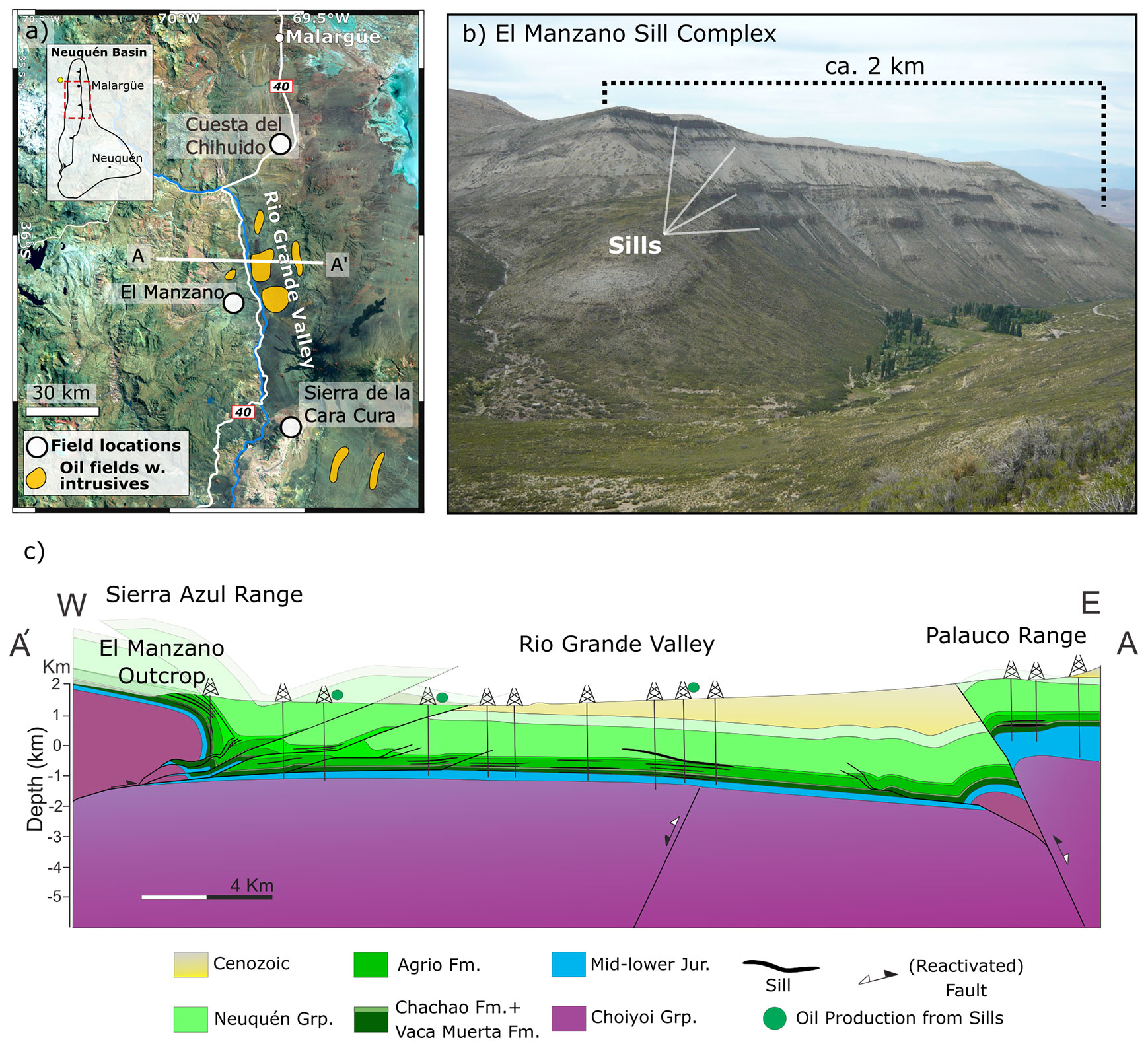
Figure 1(a) Satellite image (Landsat, courtesy USGS) of the study area in the northern Neuquén Basin including field localities (white dots) and producing igneous petroleum systems (green areas). (b) View of the El Manzano sill complex outcrop in the Sierra Azul range (photo: Federico Soto). (c) E–W structural geological section illustrating the relation between subsurface and outcropping sill complexes (courtesy Juan Bautista Spacapan).
In addition to tectonic deformation, the northern Neuquén Basin experienced intense magmatic activity that formed a series of volcanic plateaus and widespread magmatic intrusions within the sedimentary succession (Kay et al., 2006). In the study area, two main eruptive cycles, termed Molle and Huincán eruptive cycles, occurred in the late Oligocene to mid-Miocene and the late Miocene–Pleistocene, respectively (Combina and Nullo, 2005). These events led to the emplacement of extensive andesitic and basaltic sill complexes predominantly in the Vaca Muerta and Agrío formations, but also in overlying gypsum and sandstone units (Spacapan et al., 2020).
In the RGV, heavily fractured sills emplaced in the Vaca Muerta and Agrío formations constitute the reservoirs in an actively producing igneous petroleum system (Schiuma, 1994; Witte et al., 2012). Spacapan et al. (2020) reported 2 to 27 m thick sills in these shale formations, but up to 54 m within shallower clastic sediments of the RGV. Other studies from the northern Neuquén Basin report thick laccolith intrusions (>100 m) acting as reservoirs (Rodriguez Monreal et al., 2009). Spacapan et al. (2018) showed that the heat input provided by the sills matured the Vaca Muerta and Agrío shale formations, which otherwise show very low thermal maturity at burial depths of ca. 2–2.5 km. The established model for the formation of these igneous reservoirs includes the fact that the intrusions developed interconnected cooling joint networks, which subsequently stored the generated hydrocarbons (Witte et al., 2012; Spacapan et al., 2020).
In addition to the subsurface sill complexes, thrust tectonics brought exceptional analogue outcrops to the surface in the surrounding mountain ranges including the Sierra Azul, Sierra Cara Cura, and Cuesta del Chihuido (Fig. 1). Several studies describe these localities, which offer easy access to sills emplaced in the Vaca Muerta and Agrío formations (Spacapan et al., 2017; Rabbel et al., 2018; Rabbel et al., 2021). The kilometer-scale outcrops at El Manzano (Fig. 1b) and Sierra Cara Cura in particular constitute direct analogues to the subsurface sill complexes of the RGV igneous petroleum system (Palma et al., 2019; Rabbel et al., 2021). These three field localities are ideal case studies to reveal the interactions between igneous intrusions and the petroleum system.
2.2 Geological field observations
During three field campaigns, we collected an extensive dataset at outcrops in El Manzano, Sierra de la Cara Cura, and Cuesta del Chihuido (Fig. 1). We gathered ground-based and drone digital photographs to document outcrop observations. Additionally, we collected over 100 rock samples from the intrusions, surrounding shale, and various types of veins for geochemical analyses. Note that a more comprehensive description of the field study is presented by Rabbel et al. (2021).
2.3 Observations of hydrocarbons inside and around sills
Outcropping sills in all three localities feature solid bitumen and black shale inside the fracture network of the sills. At Cuesta del Chihuido, both the side and roof of thin sills are exposed, and the side view reveals upwelling dikelets of black shale (Vaca Muerta Formation) entering the sill from the bottom contact (Fig. 2a). The top view of the same sill shows the entire polygonal cooling joint network with a black fill of the same material (Fig. 2a, b). Brecciated igneous material often surrounds the dikelets where they enter the intrusion.
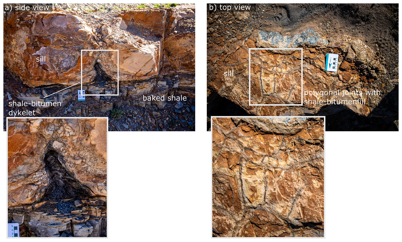
Figure 2Field observations of upwelling dikelets of liquefied shale and bitumen entering the cooling joint network of a thin sill at Cuesta del Chihuido (ca. 30 cm thick). (a) Side view showing the sediment–intrusion contact and dike (photo: Diogo Michelon). (b) Top view demonstrating black bituminous fill in the polygonal cooling joints.
The larger sills at El Manzano (Sierra Azul) and Sierra Cara Cura also show widespread bitumen in the fracture network of the sills, but at a much larger scale (Fig. 3). We observe arrays of bitumen dikes or veins (Fig. 3a) that are 1 to 50 cm thick and >10 m high. Here, the bitumen dike cuts across the contact aureole and enters the sill intrusion. We find exposures of similar structures where the sill interior is accessible (Fig. 3b). The sill appears heavily fractured in addition to pre-existing cooling joints, and solid bitumen or calcite fills nearly all fractures. On closer inspection, the bituminous material in these veins has a shiny and fibrous texture.
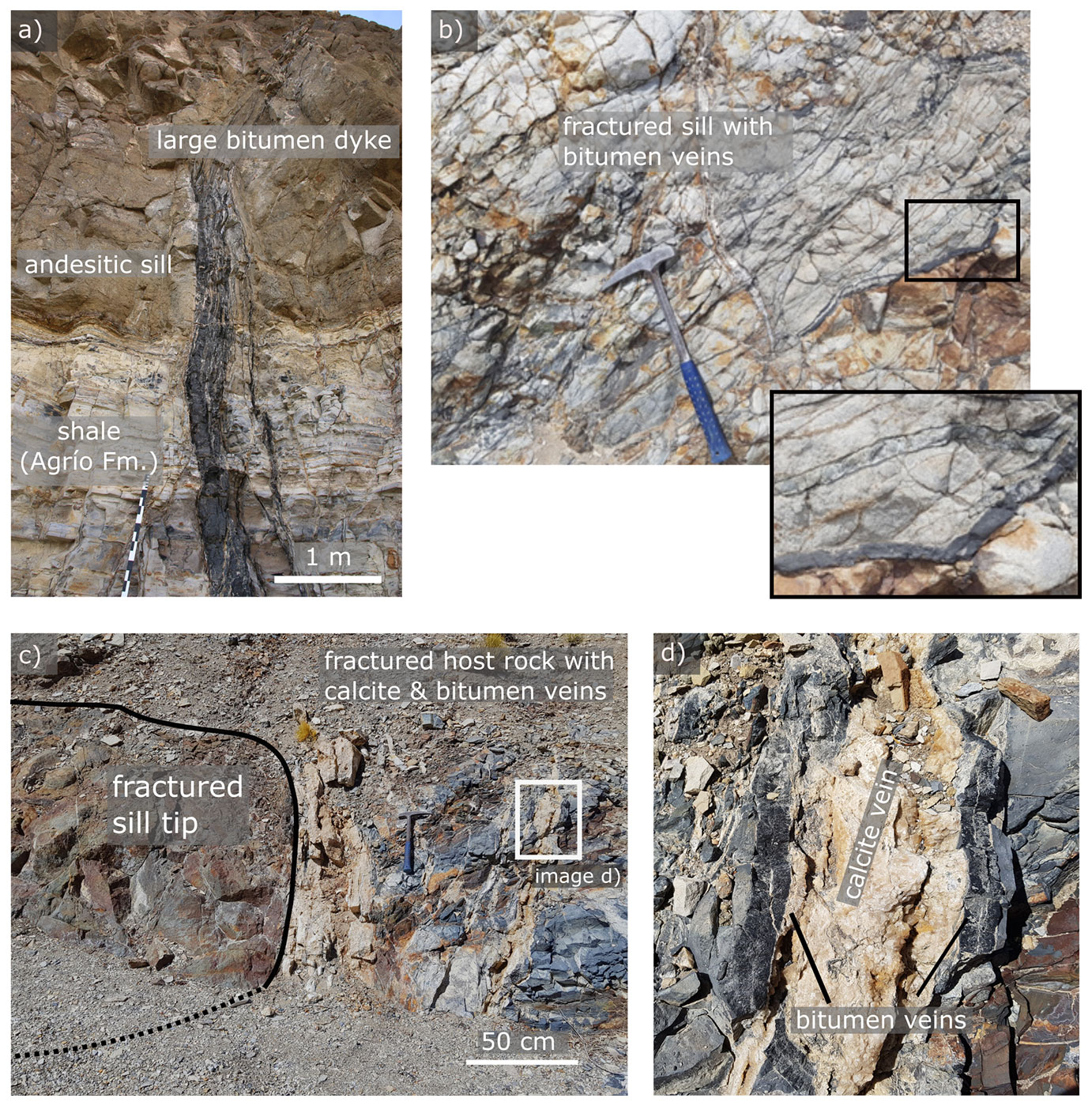
Figure 3Examples of dikes or veins of solid bitumen associated with the sill intrusions. (a) Bitumen dike at El Manzano of >10 m height and up to 0.5 m thickness originating in the aureole of the Agrío Fm. and entering the sill through the bottom contact. (b) Fractured zone inside a sill at Sierra de la Cara Cura exhibiting many centimeter-scale veins of solid bitumen. (c, d) Exposed sill tip at El Manzano showing a high concentration of fibrous bitumen and calcite veins in the contact in front of the tip.
At an exposed sill tip at El Manzano, we also observe that bitumen veins up to several centimeters thick appear to be concentrated along the tip contact, where they mutually cross-cut with calcite veins of at least similar thicknesses (Fig. 3c, d). These calcite veins have centimeter-scale pores, which occasionally contain solid bitumen themselves and release a strong hydrocarbon smell when the vein is broken up.
2.4 Bitumen characterization
The fibrous texture of the observed bitumen within the sills is intriguing and we hypothesized that it may be much higher-grade bituminous material than that described in the Neuquén Basin and commonly attributed to regional burial (Parnell and Carey, 1995; Cobbold et al., 1999; Zanella et al., 2015).
In the field, we tested this hypothesis by measuring the resistivity of the fibrous bitumen with a handheld multimeter. Graphitization of bitumen significantly changes the electric resistivity of the material: amorphous solid bitumen is very resistive and used as an electric insulator in industry applications (Hays et al., 1967), while graphite is an excellent conductor. Qualitative on-site resistivity measurements showed that the fibrous bitumen conducts electric currents well, i.e., within the detection limit of a standard multimeter, suggesting significant graphitization.
In addition, we applied Raman spectroscopy to better constrain the nature of the solid bitumen and its thermal history. Raman spectroscopy provides positions and relative intensities of spectral peaks characterizing carbonaceous materials like bitumen, including D1 (“disorder”) and G (“graphite”) peaks at 1345 and 1585 cm−1, respectively (Potgieter-Vermaak et al., 2011; Rantitsch et al., 2016). The shape of the spectra as well as the peak and area ratios allow a classification of high-grade alteration of the bitumen to anthracite or (semi-)graphite and may serve as a geothermometer for high-temperature regimes (Beyssac et al., 2002; Rantitsch et al., 2016). Due to the high temperatures within and around igneous intrusions, we expect this method to give an indication of the degree of thermal alteration and thus temperatures that the hydrocarbons experienced. Since Raman spectra can show varying absolute intensities, we normalized each spectrum to the intensity of the respective G peak (IG) for visualization purposes.
Raman spectrograms of the sampled bitumen veins show very clearly developed G and D1 peaks as well as ratios of ca. 1 and 0.9, respectively (Fig. 4). The D3 band between the peaks is nearly absent in the sample from Sierra de la Cara Cura (from vein in Fig. 3b), while it is visible at low intensity in the presented sample from El Manzano (from vein in Fig. 3a). Note that both vein samples stem from the intrusion–host contact, and each vein penetrates about 10 cm into around 20 m thick sills.
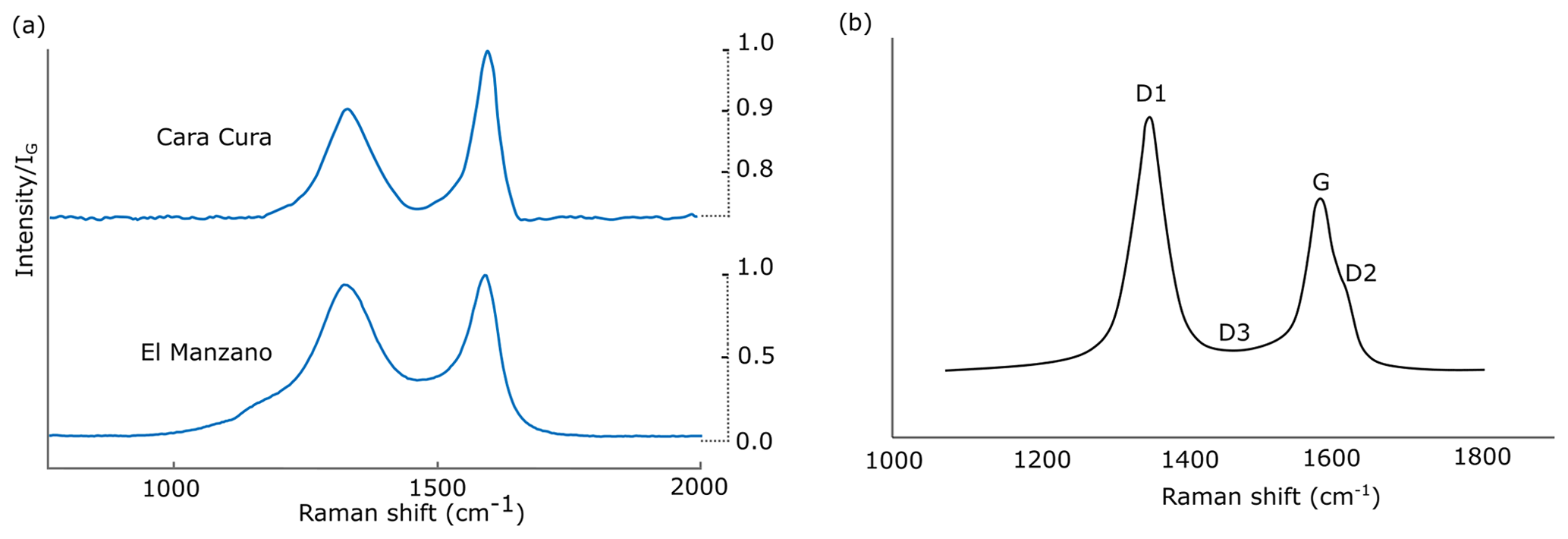
Figure 4(a) Raman spectra from two bitumen vein samples at Sierra de la Cara Cura and El Manzano. Both samples include well-developed and narrow graphite and disordered carbon (G, D1) peaks as well as a weak or absent D3 band. (b) Reference Raman spectrum to illustrate the spectra decomposition of carbonaceous material after Beyssac et al. (2002).
2.5 Composition and thermal implications of bitumen samples
We compare our Raman results with those measured in carbonaceous material from several studies, wherein increased graphitization and metamorphism lead to well-developed, narrow graphite (G) and disordered carbon (D1) peaks, weak or absent D3 bands, and peak ratios of <1 (Beyssac et al., 2002; Kwiecinska et al., 2010; Rantitsch et al., 2016). Although we did not perform quantification via peak fitting, a qualitative comparison of our results with highly metamorphosed sediments presented by Beyssac et al. (2002, Figs. 6 and 11) leads to estimated temperatures of 350–500 ∘C for our samples (Fig. 4). Hydrothermal graphitization can occur along intrusion–sediment contacts at relatively shallow crustal levels and requires temperatures of ≥400 ∘C (Buseck and Beyssac, 2014). Hydraulic fracturing focuses the flow of hydrothermal fluids oversaturated with CH4 and/or CO2 from which crystalline graphite may precipitate (Rumble, 2014). This fits well with the observations that the bitumen dikes in our study area consist of pure, often crystalline graphitic material and occupy fractured zones in the aureole, around the intrusion tip, or within the sills themselves (Fig. 3). In a previous summary of fracture types present in the sills of the study area, Rabbel et al. (2021) interpreted these features as hydraulic fractures. Thus, evidence from graphitized bitumen in the fractures in the aureole and in the sills themselves points to hydrocarbon transport in a high-pressure, high-temperature environment in which at least some of the mobilized carbon transforms to graphitic carbonaceous material.
Our field and sample results strongly suggest that significant volumes of hydrocarbons circulated through the sills when the temperatures at their margins were 350–500 ∘C. The temperature was thus likely much higher in the interior of the sills. We infer that hydrothermal flow also occurred along cooling fractures within the sill; i.e., the sill developed some permeability while still hot (see Fig. 2). This interpretation challenges the common assumption of previous models of hydrothermal circulation around cooling sills that intrusions remain impermeable during cooling (Aarnes et al., 2012; Iyer et al., 2017; Galerne and Hasenclever, 2019). An exception is the study of Iyer et al. (2013), who tested a model that included a linear permeability increase inside a cooling sill. While the authors highlighted the importance of this mechanism in potentially facilitating the upward migration of thermogenic gas generated beneath sills, this test remained exploratory. Hence, no detailed analysis of the effect on the hydrothermal flow is provided or supported by field evidence. Thus, a dedicated modeling study on the effect of permeability creation in cooling sills on hydrothermal flow and hydrocarbon transport is still missing. In the following section, we therefore present numerical simulations to test the effects of permeability increase associated with fracturing within the sills on hydrothermal circulations and how this affects hydrothermal transport of hydrocarbons around sills.
3.1 Model description
We employ the two-dimensional (2D) finite-element model of Galerne and Hasenclever (2019), who applied it to quantify degassing through sill-related hydrothermal vents. The model is presented in detail in Galerne and Hasenclever (2019). Here we will limit our discussion to the main features and point out the key adjustments made for this study. In short, the model simulates hydrothermal flow around a cooling sill, but is also coupled to a model for the heat-driven chemical transformation of organic matter into hydrocarbons (represented by methane). This allows us to investigate not only hydrothermal circulation around sills as such, but also how this affects transport of the hydrocarbons generated in the contact aureole.
The model considers single-phase hydrothermal flow of a compressible fluid in a porous medium following Darcy's law. Temperature calculations comprise heat diffusion, heat advection, and heat sources and sinks related to latent heat of magma crystallization, mineral dehydration, thermal cracking of organic matter, and internal fluid friction as well as pressure–volume work. Fluid density varies with temperature and pressure according to the equation of state of pure water. The pore pressure equation also contains source terms representing fluid release due to temperature-dependent, irreversible contact metamorphic reactions, including (i) organic matter transformation into methane and (ii) clay mineral dehydration.
To calculate organic matter transformation to light hydrocarbon, the model uses the EASY%Ro method (Sweeney and Burnham, 1990), which quantifies the converted fraction of organic matter and thermal maturity through vitrinite reflectance Ro. Here we assume that all organic matter is converted to methane. We monitor transport and accumulation of the released methane due to hydrothermal flow using a finite-volume advection scheme but do not consider buoyancy effects resulting from the addition of methane to the pore fluid. Clay mineral dehydration follows the maximum storable weight fraction of water in the stable mineral assemblage at a given temperature, which is predicted by phase equilibria (Connolly, 2009). This process not only produces additional pore fluid, but also causes a permanent porosity increase in the affected host rock to ensure mass conservation of rock and fluid. The brittle–ductile transition for the host rock is assumed to happen at 500–750 ∘C and linearly decreases permeability (Galerne and Hasenclever, 2019). Note here that while the model calculations are conducted with methane properties, the results can be used to understand transport of (light) hydrocarbons around sills in general. We thus use “methane” and “hydrocarbons” interchangeably in the context of this study.
The model provides time series of the 2D fields of all relevant rock properties in the model domain and physical quantities related to metamorphism and hydrothermal flow. Since we investigate the impact of permeable sills on the fluid and hydrocarbon circulation, our analysis focuses on visualization of the temperature, permeability, fluid flow, and methane accumulation during cooling of the sill.
3.2 Adjustments for this study
We adjusted three aspects of the original model to honor geological observations in the study area. First, we limit rock failure to tensile hydraulic fracturing and do not consider shear failure. We assume that hydrofracturing occurs at sufficiently high pore fluid overpressure, i.e., if pore pressure exceeds the sum of lithostatic stress and tensile strength. Here, we consider hydrofracturing of the host rock and not within the sill.
Second, we assume that hydrofracturing increases not only permeability but also porosity, which is often neglected in numerical models for simplicity. However, the additional space provided by the opening of hydraulic fractures, which we approximate by the porosity increase, is an important storage buffer during thermal expansion of fluids and hydrocarbon generation. While a transient permeability increase during hydrofracturing can easily be defined without affecting the numerical stability and physical plausibility of the model, prescribing a porosity increase associated with hydrofracturing is not straightforward. A prescribed porosity increase that is too large, for instance, would create a strong suction effect, leading to unrealistically low pressures or even underpressure. We solve this problem by iteratively increasing porosity in regions where overpressure exceeds the failure criterion and solving again for the pore pressure field until a consistent solution is established, which on average requires 10–15 iterations. Hydrofracturing is treated as reversible and its effects on porosity and permeability vanish once pore pressure drops below the failure criterion. In this study, we limit the hydrofracturing-related maximum porosity and permeability increase to 1 % and a factor of 100, respectively.
Third, we approximate the process of cooling joint formation within the sill through a linear temperature-dependent permanent increase in permeability, similar to Iyer et al. (2013), but additionally consider the corresponding permanent porosity increase. Note that this is likely a strong simplification of fracture flow through cooling joint networks, which is still poorly constrained. Bulk volume reduction of the cooling and crystallizing magma induces thermal stresses that lead to the formation of a cooling joint network, creating primary porosity and permeability inside the intrusion (e.g., Petford, 2003; Hetényi et al., 2012). The overall pore space gained in our model is set to equate to 8 % volume loss, occurring during the transition from a melted to crystallized magma (between the liquidus and solidus temperature), based on reported fracture porosities from fractured sill reservoirs in the study area (Witte et al., 2012; Spacapan et al., 2020). To be consistent with the crystal-mush model described by Marsh (2002), the onset of the pore opening should be when 50 %–55 % of the magma has crystallized. Here we take a value of 1000 ∘C as the onset of the brittle–ductile transition (BDT) temperature. Using a linearized, temperature-dependent definition of the melt fraction, (), with TL=1100 ∘C and TS=900 ∘C being liquidus and solidus temperatures, respectively, the set value for the BDT in our simulations implies that cooling joint creation starts at 1000 ∘C when, at any distance from the sill margins, 50 % of the sill has crystallized (Fig. 5c).
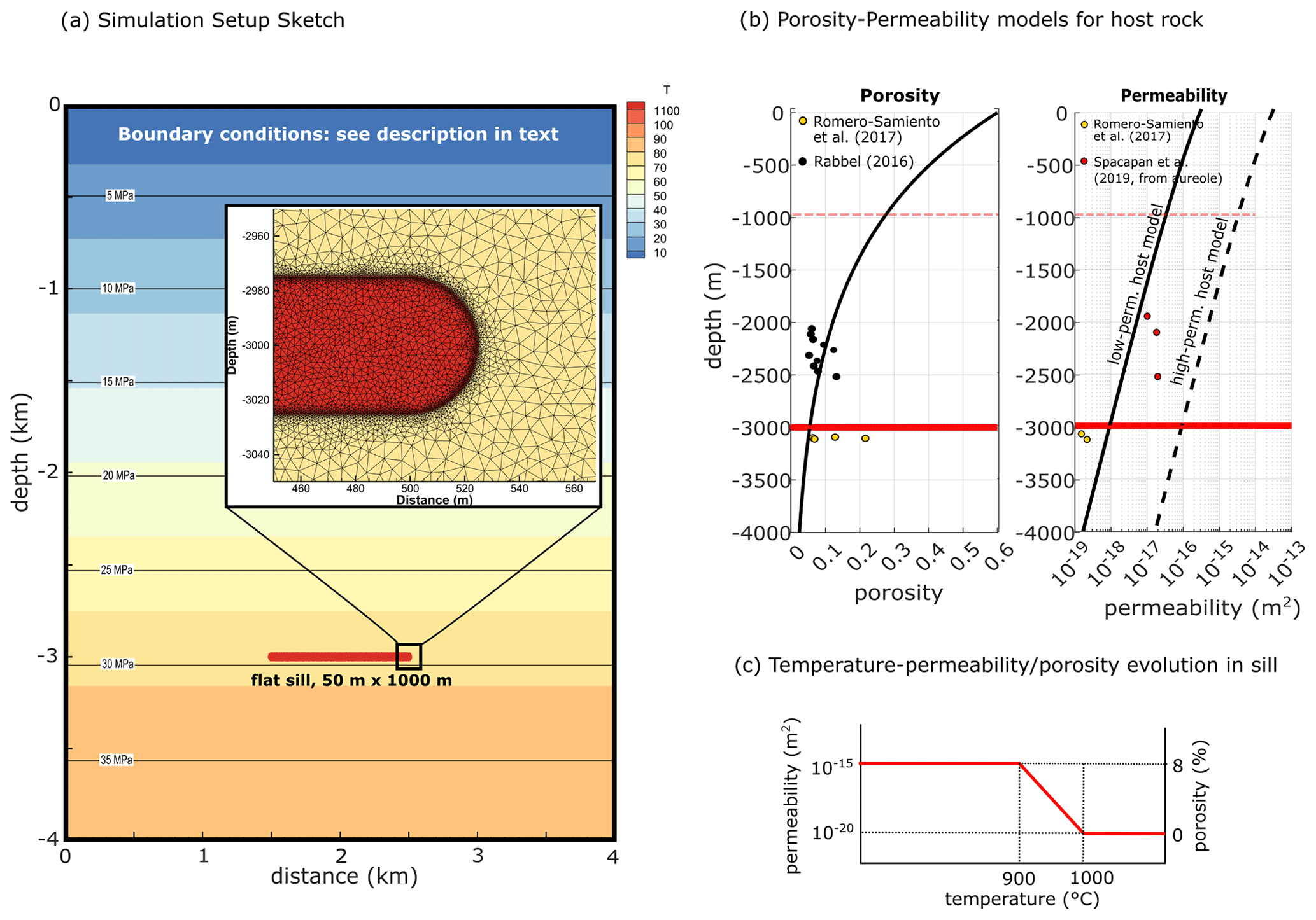
Figure 5Illustration of the numerical modeling setup. (a) Model domain, with initial temperature and pore pressure field as well as a close-up for mesh illustration. (b) Porosity–permeability–depth relationships in the models alongside reported data from the Vaca Muerta formation from various depths (Rabbel, 2017; Romero-Sarmiento et al., 2017; Spacapan et al., 2019). Note that permeabilities from Spacapan et al. (2019) are the smallest values reported from the fractured and altered aureole of sills and thus likely overestimate background values. (c) Illustration of porosity–permeability–temperature function for a sill with assumed cooling joint formation.
Note that we limit the model's representation of fracturing in the sill to cooling joints and thus perform a strong simplification compared to the complex interplay of thermal and hydraulic fracturing mechanisms observed in the field (see Sect. 3 and Rabbel et al, 2021). However, the goal is to study the general impact of porous and permeable sills on hydrothermal flow and the associated hydrocarbon transport and storage, which is possible even with this limitation.
3.3 Modeling setup
Our modeling setup consists of a single flat sill of 50 m thickness and 1 km length emplaced at 3 km depth in a homogenous host rock (Fig. 5a). We performed a parameter sensitivity study to investigate the impact of porosity and permeability development in sills emplaced in either low-permeability (e.g., shale) or high- to medium-permeability (e.g., siltstone and sandstone) host rocks. This allows us to investigate the sills of our study area (sills in Agrío and Vaca Muerta shales), but also compare to sills in the overlying Neuquén Group (siltstones and sandstones) or other relevant geological settings. Figure 5 and Table 1 show the model setup and the list of important model parameters, respectively. Note that we also carried out simulations with thinner sills and provide those in the Supplement for completeness but do not address their results in detail. We first conducted a series of reference setups including permanently impermeable sills emplaced in either high- or low-permeability host rock. Subsequently, we use the same setups but activate temperature-dependent porosity and permeability generation for the sills. Hydraulic fracturing of the host rock is activated in all simulations.
Table 1Material properties used for hydrothermal simulations.
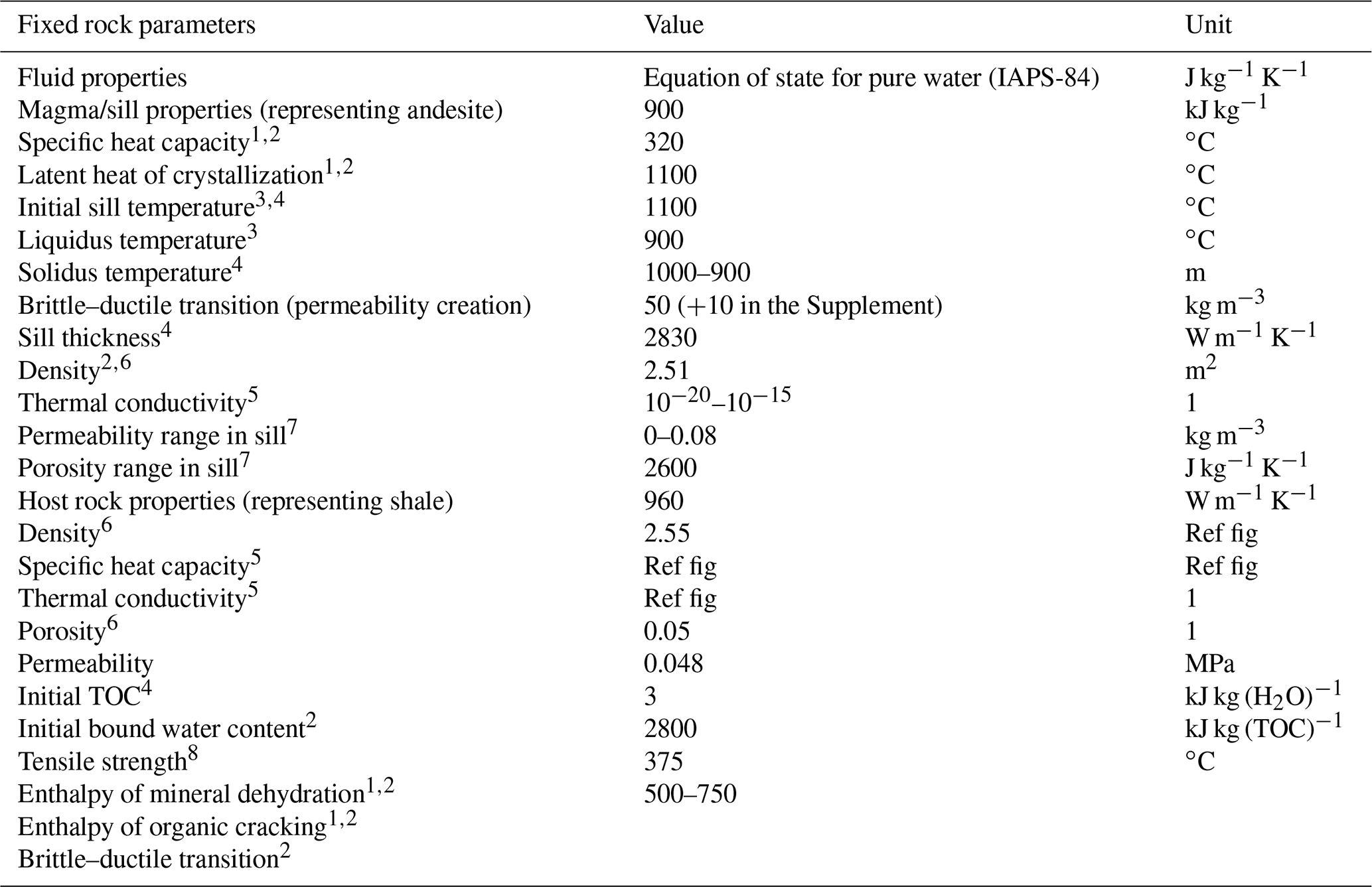
Sources: 1 Aarnes et al. (2010), 2 Galerne and Hasenclever (2019), 3 Stern et al. (1975) ,4 Spacapan et al. (2018), 5 Angenheister et al. (1982), 6 Rabbel (2017), 7 Spacapan et al. (2020), 8 Schön (2015).
The model domain (Fig. 5a) is 4000 m wide, extends from the surface to 1000 m below the emplacement depth of the sill, and is discretized with a triangular mesh with variable element sizes between 0.5 and 50 m (smallest around and within the sill, see Fig. 5c). We assume instantaneous sill emplacement at 1100 ∘C, corresponding to the inferred liquidus temperatures of andesitic magma in the study area (Spacapan et al., 2018). The left and right boundaries are insulating and impermeable, and we calibrated the fixed temperature at the impermeable bottom boundary to create a geothermal gradient of around 25 ∘C km−1. The top boundary mimics the behavior of a shallow seafloor with temperature set to 10 ∘C, pressure set to 0.1 MPa, and free inflow and outflow. Otherwise, initial conditions consider no basin history, such as uplift and erosion, and no pre-existing thermal maturation prior to sill emplacement. We justify this with low background maturity values reported in the study area (Spacapan et al., 2018; Palma et al., 2019; Rabbel et al., 2021).
For the sediments, we chose a homogenous material with 5 % TOC and ca. 5 weight % bound water, as well as exponential decay of porosity with depth (Fig. 5b). Permeability is porosity-dependent and follows a Kozeny–Carman relationship. This relationship is calibrated to values of low-permeability Agrío and Vaca Muerta shale formations at 2–3 km depth in the northern Neuquén Basin, yielding 10−18 m2 at 3 km. This corresponds to emplacement depths for the igneous petroleum systems present in both the subsurface and outcrop (Fig. 5b). To compare with settings with more permeable lithologies (siltstone and sandstone), we increased the host rock permeability by 2 orders of magnitude for another set of simulations (Fig. 5b). Yet, each host rock setup remains a simplification, as we do not include lithological variations. Sill permeability starts at 10−20 m2 (impermeable) and increases to 10−15 m2 at 900 ∘C. In the absence of macroscopic permeability measurements, we chose the maximum permeability value to approximate the upper range for Neuquén sill reservoirs as reported by Spacapan et al. (2020). These values were obtained from (micro)fractured sill matrix samples and therefore likely underestimate bulk permeability, as they do not include macroscopic cooling joints.
3.4 Numerical simulation: results
3.4.1 Impermeable sill: flow around sill tip and methane plume
We first present and compare the results of the reference simulations of a 50 m thick, impermeable sill emplaced at 3 km depth in either a low-permeability (Fig. 6) or high-permeability (Fig. 7) host rock. Figures 6 and 7 display the evolution of temperature, vitrinite reflectance (Ro) as a proxy for thermal maturity (first row of images), pore fluid pressure (second row), permeability and transiently opened fracture porosity to highlight regions of active hydrofracturing (third row), and the methane fraction of the fluid (fourth row) in the model at 1, 60, and 1000 years after the sill is emplaced. Additionally, flow vectors colored by fluid velocity in the pore space are shown. We highly recommend also viewing the movies supplied in the Supplement of this paper to get a better sense of the process dynamics in space and time.
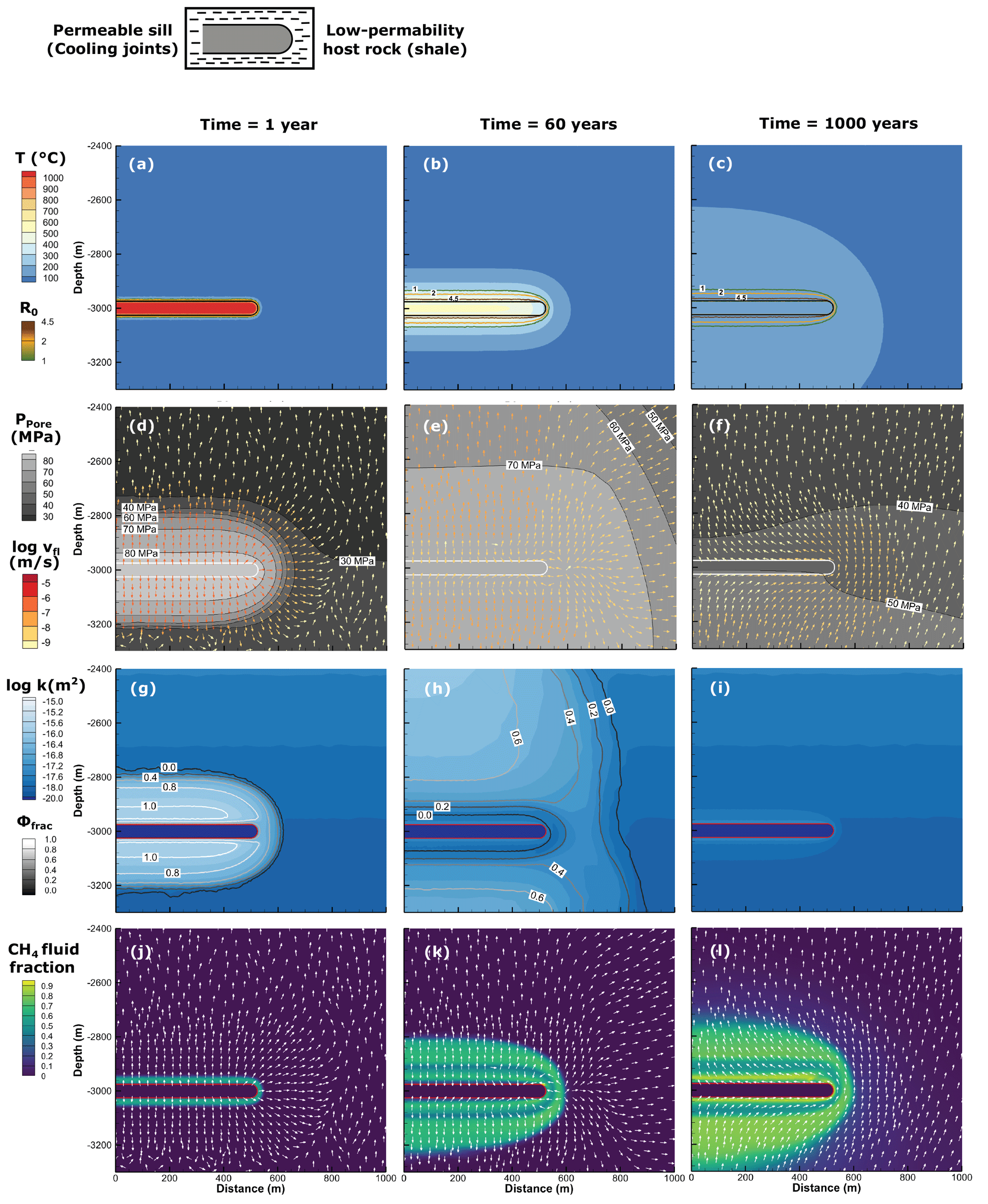
Figure 6Reference simulation results for an impermeable sill of 50 m thickness at 3 km depth in the low-permeability host case. The columns correspond to 1, 60, and 1000 years of simulated time after emplacement, respectively. The rows represent four parameters characterizing thermal state, contact metamorphism, and hydrothermal transport of methane: (a–c) temperature and thermal maturity as vitrinite reflectance R0 contours, (d–f) pore fluid pressure with flow vectors colored by pore velocities, (g–i) permeability with fracture porosity contours, and (j–l) methane fraction in fluid.
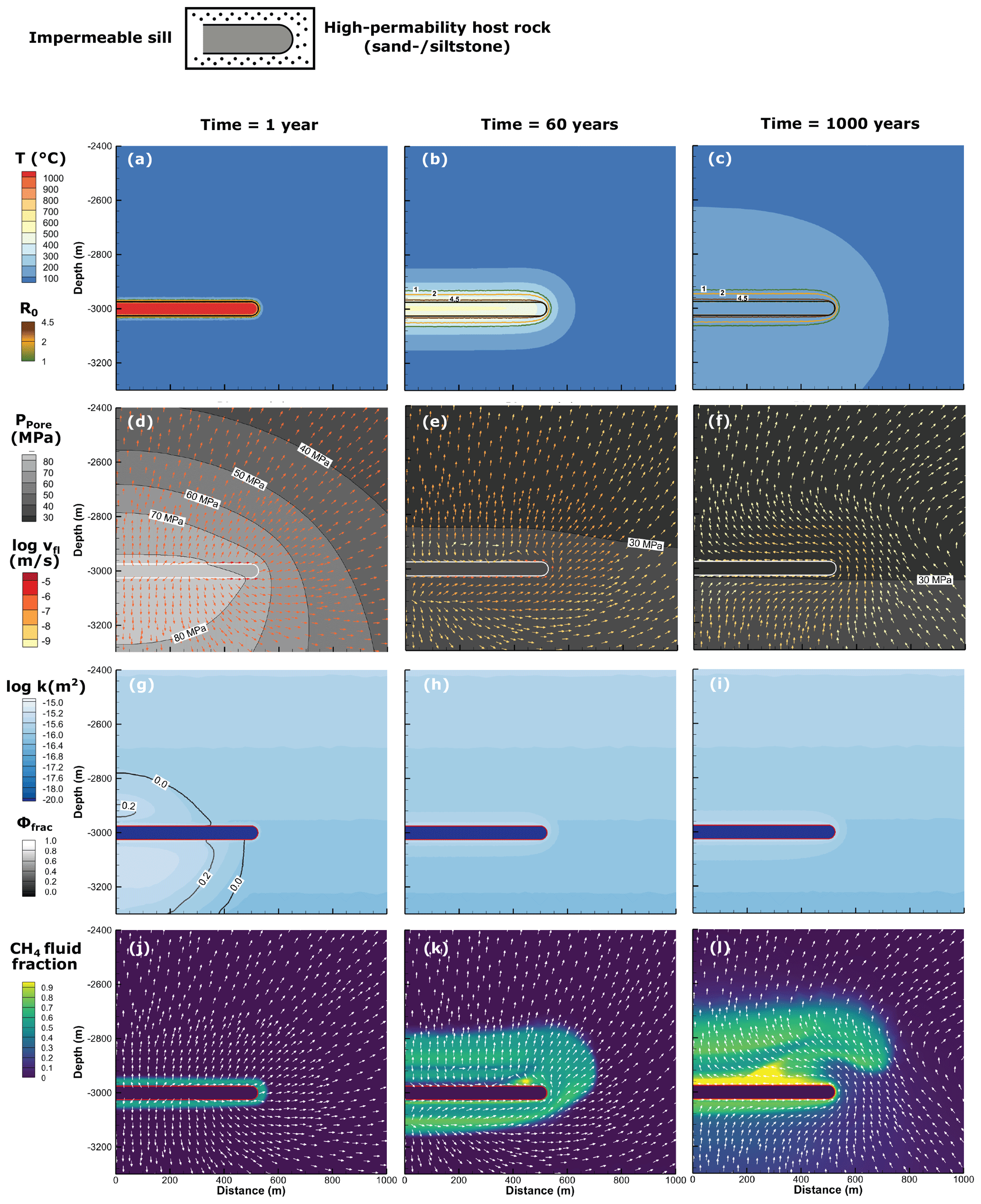
Figure 7Reference simulation results for an impermeable sill of 50 m thickness at 3 km depth in the high-permeability host case. The columns correspond to 1, 60, and 1000 years of simulated time after emplacement, respectively. The rows represent four parameters characterizing thermal state, contact metamorphism, and hydrothermal transport of methane: (a–c) temperature and thermal maturity as vitrinite reflectance R0 contours, (d–f) pore fluid pressure with flow vectors colored by pore velocities, (g–i) permeability with fracture porosity contours, and (j–l) methane fraction in fluid.
At 1 year after emplacement (left column in Figs. 6 and 7), the sill is still over 1000 ∘C hot and only the host rock within <10 m distance to the sill has been heated to temperatures of >350 ∘C. Within the thin thermal aureole, thermal maturity increases strongly, methane is generated by thermal cracking, and mineral dehydration takes place. Thermal expansion of the heated fluid, mineral dehydration, and methane generation close to the sill lead to strongly elevated pore fluid pressures, which propagate away from the sill (Figs. 6d and 7d). In both low- and high-permeability scenarios we observe similar peak pore pressures of around 80–85 MPa at the sill contact during the first weeks after the sill emplacement. However, in the high-permeability case (Fig. 7d), the pressure front moves faster because of efficient fluid flow even far away from the sill. In contrast, the pressure front moves much slower in the low-permeability case (Fig. 6d), wherein fast fluid flow is restricted to the region of active hydrofracturing (Fig. 6g vs. Fig. 7g). Flow direction and therefore methane transport are sill-parallel towards the tips in the highly permeable contact aureole and radially outwards outside the aureole (Figs. 6d, j and 7d, j).
After 60 years of sill cooling (central column in Figs. 6 and 7), the high-temperature aureole (>350 ∘C) has expanded to ca. 25 m around the sill (Figs. 6b and 7b), and thermal maturity has reached Ro values above 2, which indicates the gas window or overmaturity. At this stage, pore pressure and permeability distribution in the two reference cases differ markedly. In the low-permeability host, fluid overpressure is still sufficiently high to cause hydrofracturing in a halo several hundred meters wide around the sill, where permeability is elevated by 1–2 orders of magnitude with respect to background values (Fig. 6e, h). Note that hydrofracturing is vanishing close to the sill where hydrofractures are closing again as pore pressure is slowly reduced. The high-permeability host allows for a more efficient dissipation of fluid overpressures so that no more hydrofracturing occurs ca. 10 years after the sill emplacement. After 60 years, the remaining fluid overpressure around the sill is only a few megapascals (MPa) above hydrostatic (Fig. 7e, h). Both models also develop porosity and permeability increases due to clay mineral dehydration, but this is limited to 50 m distance from the sill contact. In both models, the highest temperature in the inner aureole (ca. 10 m from contact) is reached ca. 10 years after the sill emplacement (around 670 ∘C at the sill contact), while the outer aureole (up to ca. 50 m to contact) reaches its peak temperatures (300–400 ∘C, depending on distance to sill) after around 60 years. The combined action of thermal contraction of the cooling fluid after reaching the peak temperature and additional closure of hydrofractures (i.e., pore space reduction) in the low-permeability host causes an inversion of the flow direction. After 60 years, fluids carrying high methane concentrations migrate towards the sill within a ∼ 100 m thick region above and below the sill (Figs. 6e, k, 7e, k and movies in the Supplement). Despite the differences in permeability structure and pressure regimes, flow patterns of both reference simulations are relatively similar. The contact-parallel flow in the high-permeability host is stronger, and these higher flow velocities lead to a more pronounced plume of rising methane on top of the sill near its tip (Fig. 7k). Both cases also show a sizable methane accumulation remaining below the sill.
The right column in Figs. 6 and 7 represents the end of the simulation after ca. 1000 years. The temperatures throughout the model are still elevated with respect to the initial geotherm but are now below 200 ∘C everywhere. Fluid pressure in the low-permeability case is still up to 20 MPa above hydrostatic but has dropped below the failure criterion and hydrofracturing has stopped (Fig. 6f, i). In the high-permeability host, pore pressure is reduced to values of <1 MPa above hydrostatic (Fig. 7f). The dehydration-related permeability increase has not expanded significantly in either model. In the low-permeability scenario, some of the methane rises to 250 m above the sill, but the highest concentrations (almost pure methane, i.e., mass fraction close to 1) occur within 50–100 m of the sill contact (Fig. 6l). In contrast, the model with a high-permeability host shows the formation of a localized secondary plume of very high methane concentrations (essentially pure methane) rising above the sill (Fig. 7l), and the initial methane plume has reached ca. 400 m above the sill. The aureole below the sill has also accumulated a high methane concentration in the fluids with >70 % methane fraction within 30 m of the sill. These methane-rich fluids remain trapped below the impermeable sill.
3.4.2 Permeable sill: opened upward flow path and flow reversal
The introduction of cooling-related permeability generation in the sill profoundly changes the development of hydrothermal flow and methane transport patterns for both host rock types. We show identical parameters and time steps as for the reference simulations for low- and high-permeability host in Figs. 8 and 9, respectively. To describe the details of the evolving flow patterns and hydrocarbon transport in the first 60 years, we add close-up figures for both cases displaying fluid pressure with flow vectors and permeability plots with (transient) fracture porosity (Fig. 10). Finally, we quantify the total generated methane mass, the methane mass exposed to temperatures >400 ∘C (graphitization conditions), the accumulation of methane in the permeable and porous sill, and the average sill temperature over time (Fig. 11). Again, it is instructive to also view the movies in the Supplement for the respective simulations.
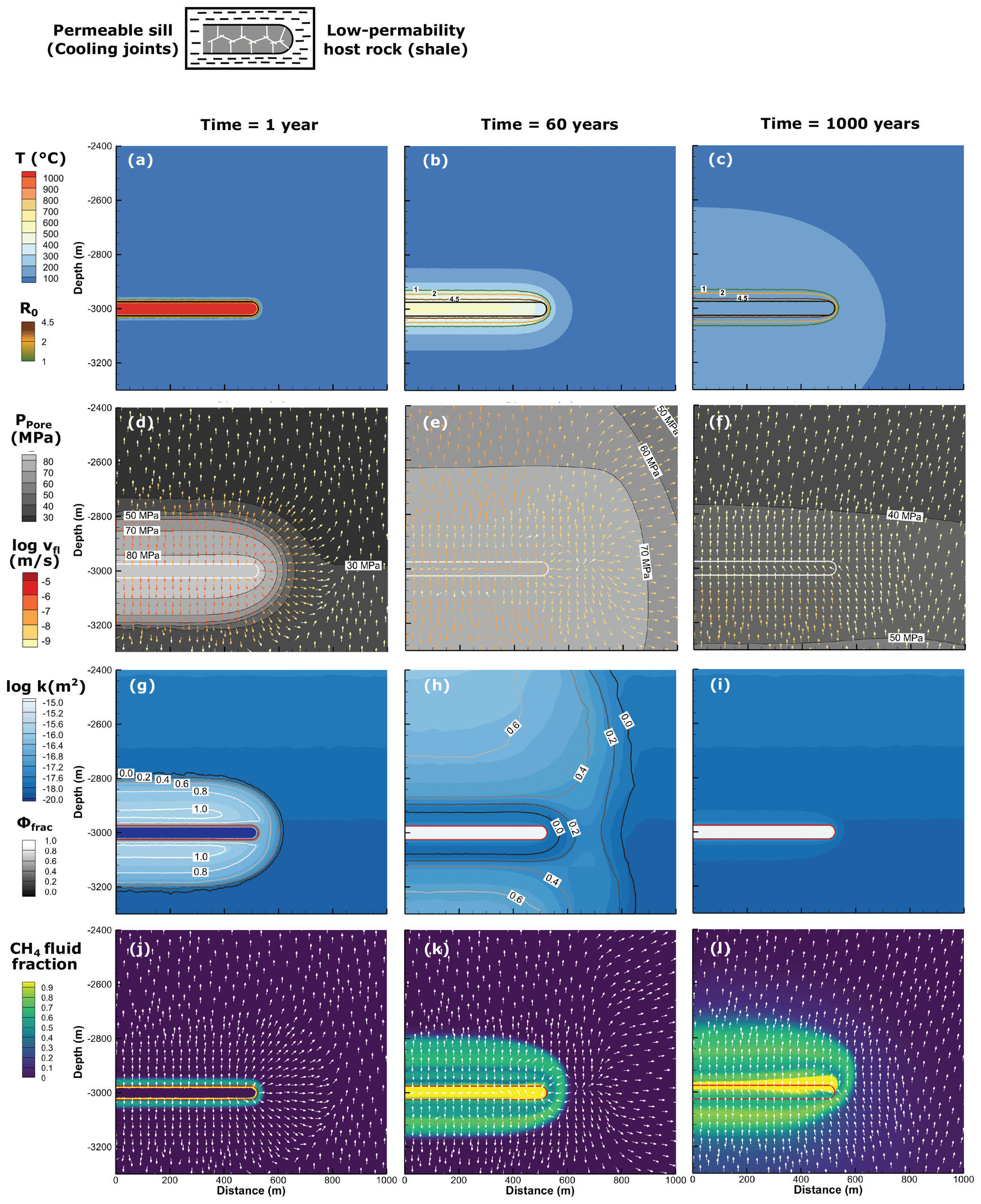
Figure 8Simulation results for identical conditions as the reference case in Fig. 6 (50 m thick, 3 km depth, low-permeability host), but the sill develops porosity and permeability with cooling. The rows represent four parameters characterizing thermal state, contact metamorphism, and hydrothermal transport of methane: (a–c) temperature and thermal maturity as vitrinite reflectance R0 contours, (d–f) pore fluid pressure with flow vectors colored by pore velocities, (g–i) permeability with fracture porosity contours, and (j–l) methane fraction in fluid.
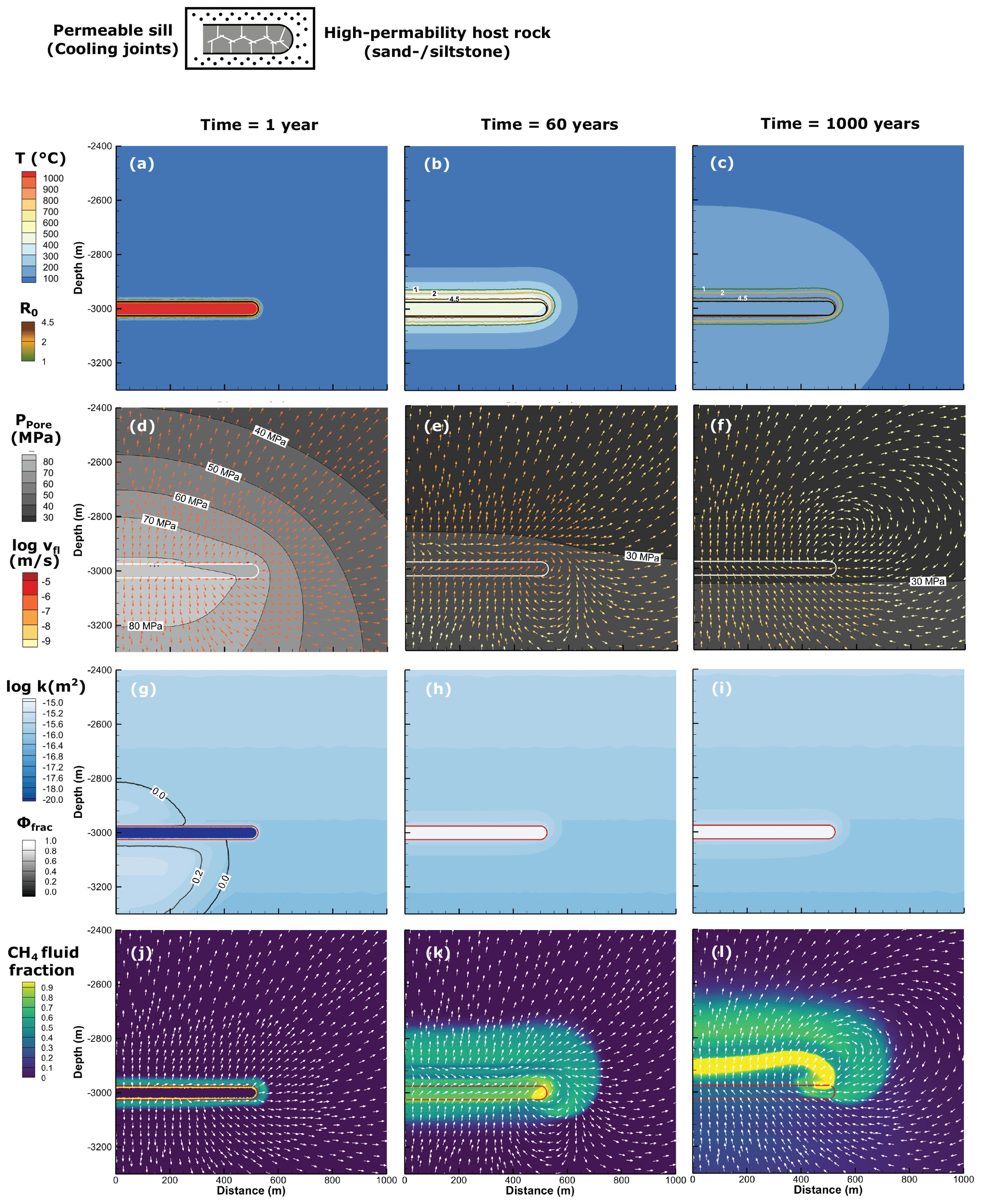
Figure 9Simulation results for identical conditions as the reference case in Fig. 7 (50 m thick, 3 km depth, high-permeability host), but the sill develops porosity and permeability with cooling. The columns correspond to 1, 60, and 1000 years of simulated time after emplacement, respectively. The rows represent four parameters characterizing thermal state, contact metamorphism, and hydrothermal transport of methane: (a–c) temperature and thermal maturity as vitrinite reflectance R0 contours, (d–f) pore fluid pressure with flow vectors colored by pore velocities, (g–i) permeability with fracture porosity contours, and (j–l) methane fraction in fluid.
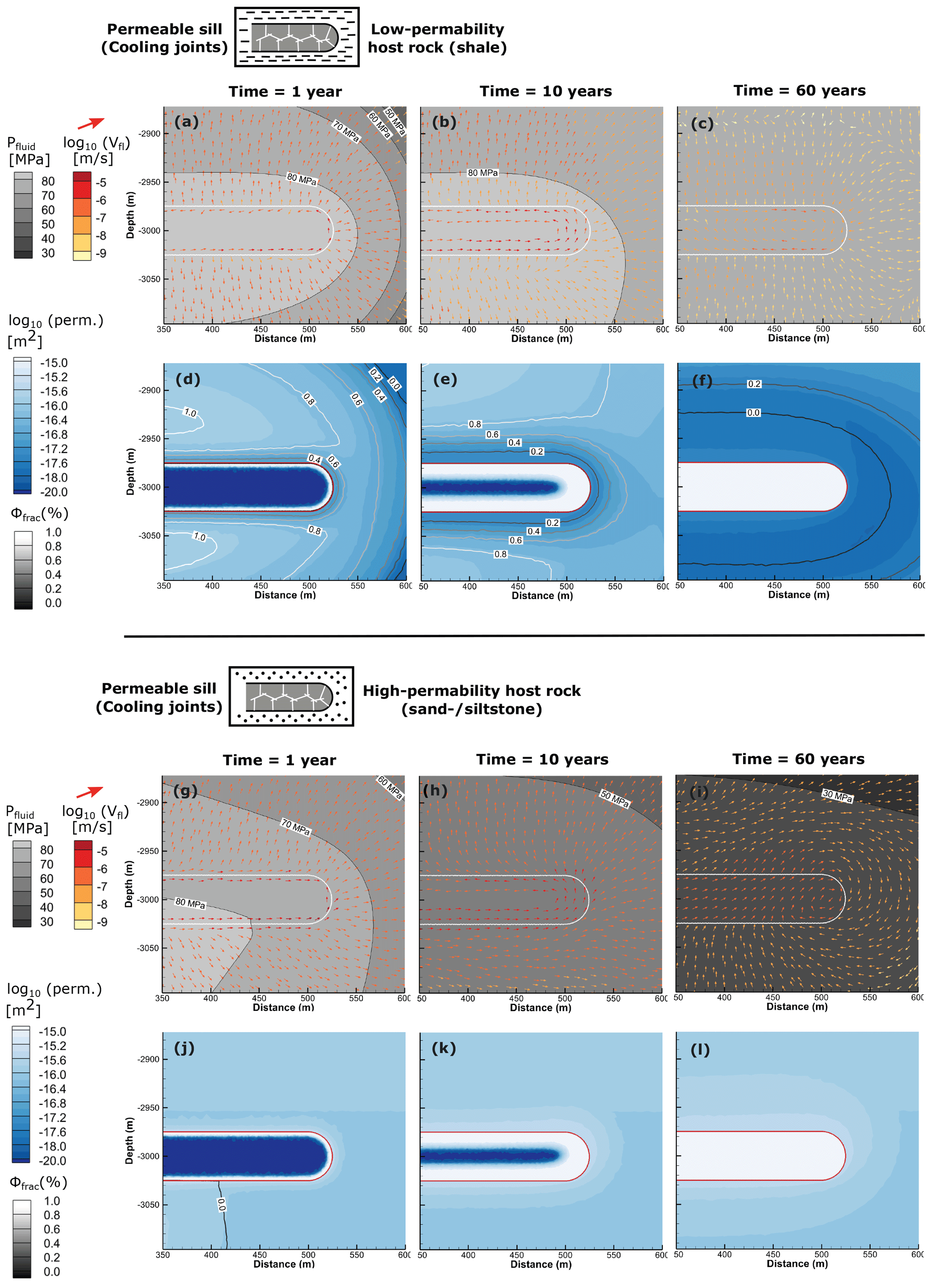
Figure 10Close-up view of fluid pressure with flow vectors and permeability with fracture porosity contours at 1, 10, and 60 years of the permeable sill simulations in low-permeability (a–f) and high-permeability (g–l) host rocks.
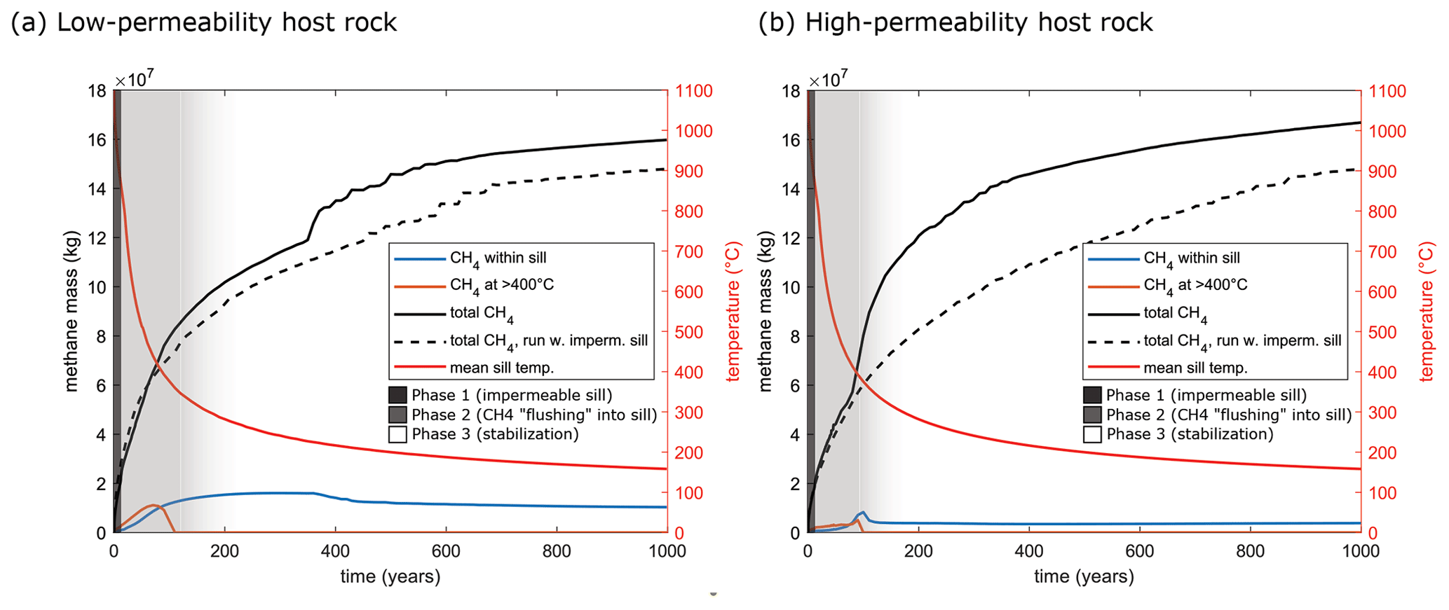
Figure 11Cumulative methane mass for the simulations with permeable sills in a low-permeability host (a) and high-permeability host (b) grouped by different criteria: within rock at >400 ∘C, i.e., sufficient for graphitization (orange line), within sill (blue line), and total mass generated in the model (black line). The dotted black line gives the total generated methane mass for the respective reference simulation with an impermeable sill. The red line represents the average sill temperature.
A total of 1 year after emplacement, initial cooling of the sill leads to a progressing porosity–permeability front where the temperatures approach the solidus defined as 900 ∘C (Figs. 8 and 9, left column). At this stage, which continues until the sill becomes fully permeable, the simulations closely resemble the reference runs (see also animations in the Supplement). Temperatures in the sediments are elevated only close to the intrusion, where the sediments almost instantly produce gas or become thermally overmature; i.e., vitrinite reflectance is larger than 1.5 (Figs. 8a, 9a). Again, pore pressures are strongly elevated, and porosity and permeability in the sediments increase due to hydrofracturing around the sill (Figs. 8d, g and 9d, g). Although large-scale methane distribution appears nearly identical to the reference scenarios, the detailed view shows that the onset of porosity and permeability generation in the sill's outermost regions allows flow within the sill (Fig. 10, first and second column). Nevertheless, most fluid flow and methane transport are directed away from the sill contact with some sideways flow towards the sill tip along the bottom contact.
The entire sill has become fully porous and permeable after about 12 years (just after Fig. 10, second column). While the same processes as described for the reference cases take place here as well (vanishing hydrofracturing, cooling of the contact aureole, fluid contraction, and beginning inversion of the flow field towards the sill), the opening of the sill leads to stronger and more focused flow towards it. The flow direction below the sill changes from downward or contact-parallel to nearly vertical upwards (Figs. 8e, 9e), “flushing” high methane concentrations directly into the sill (Figs. 8k, 9k, 10c, i). However, at this point there are differences between the simulations considering a low- vs. high-permeability host rock.
In the low-permeability case, a convection cell evolves within the sill, whose permeability is 2–3 orders of magnitude higher than that of the surrounding shale (Fig. 10c). Methane transport into the sill is further enhanced by the much slower overpressure dissipation through this host rock and the fading hydrofracturing. After 60 years, hydrofracturing and the associated fracture porosity are progressively reduced and eventually stopped near the sill (Figs. 8h, 10f), where fluid pressures have dropped below the failure criterion. The pressure drop is primarily caused by thermal contraction of the cooling fluids in the aureole and within the cooling sill. While the front of fading hydrofracturing and associated fracture porosity propagate away from the sill, methane-rich fluid is “squeezed” out of the host rock (Figs. 8l, 10c, f) and contributes to a sustained flow and methane transport towards the sill. In this way, the sill is charged with up to 11 000 t of methane (7.5 % of total generated methane) within the first 100 years (Fig. 11a). Methane mass in the cooling sill rises to ca. 16 000 t (8.8 % of total) after 250 years.
In the high-permeability host rock, the porosity and permeability structure are much simpler because hydrofracturing is absent due to generally lower fluid pressure (Fig. 9e). The permeable sill and its dehydrated aureole, with slightly higher permeability than the background (Figs. 9h, k, 10l), now represent an upward pathway and storage layer for methane-rich fluids. In addition to upward flow from below the sill, the flow directions at the intrusion tip also change and a circular flow pattern develops centered around a vortex located at the top of the intrusion tip (Figs. 9e, 10i). This vortex initiates a sideward- and downward-directed flow that transports some of the methane from above and next to the sill tip back towards and into the sill tip (Fig. 9k). During this phase of “methane flushing”, more methane enters the sill from below and through the tip than is lost through the top contact, and thus methane stored in the intrusion rises to 10 000 t (6.3 % of total) until ca. 90 years of simulation time (Fig. 11b).
Interestingly, in both cases the average temperature in the sill during this stage of “flushing” is still between 400 and 800 ∘C (Fig. 11). Thus, up to 7.5 % of the overall generated methane that reaches the sill and the innermost 10–20 m of the aureole in the first ca. 100 years is exposed to these temperatures.
In the following phase until the end of both simulations, the sill and sediments cool down to below 200 ∘C, thermal maturity increases only marginally, and fluid pressures dissipate to a level below the hydrofracturing point (right columns in Figs. 8 and 9). In the simulation comprising a low-permeability host rock, the highest methane concentrations accumulate within the sill or within 50 m of the upper contact (Fig. 8l). In the high-permeability case, the release of methane previously trapped under the sill creates a slowly rising band of very high methane concentrations above the sill (Fig. 9l). Flow velocities have been further reduced by another 2 orders of magnitude, indicating that hydrothermal flow is stalling. In the last few hundred years of each simulation, the methane amount in the sill is reduced to about 10 000 t (5.5 % of total) and 4000 t (2.5 % of total) (Fig. 11).
In summary, we identify three hydrothermal flow phases in the case of a sill with porosity and permeability evolution due to cooling joint formation. These include the following: (i) fluid flow and methane transport away from the sill and contact-parallel as long as the sill core is impermeable; (ii) partial backflow and “methane flushing” into or through the sill once it is completely fractured (in low-permeability environments, this phase is accompanied by the closure of hydrofractures around the sill, thereby “squeezing out” methane-rich fluids that enter the sill); and (iii) stabilization of hydrocarbon in and around the sill during fading hydrothermal circulation.
Despite the differences in the physical behavior between low- and high-permeability host rocks in phase (ii), i.e., fracture-facilitated fluid flow vs. matrix flow, substantial amounts of methane-rich fluids from below enter the porous and permeable sill shortly after its solidification at 900 ∘C. Compared to the simulations with impermeable sills, fluid overpressures dissipate slightly faster in the same host rock type because the opening of pore space in the sill compensates for a small fraction of the overpressure.
4.1 Hydrocarbon transport through hot sills
Outcrop data strongly suggest that transport of hydrocarbons generated around the sills in the northern Neuquén Basin occurs both vertically through the igneous intrusions and around their tip. Importantly, geochemical data from the study area suggest that the sills are responsible for most, if not all, organic matter transformation in the host rock because background maturity between the sills is essentially zero (Spacapan et al., 2018; Rabbel et al., 2021). We thus interpret the observed hydrocarbons in the field to result from magmatic heating and hydrothermal activity rather than burial-related maturation.
Cooling joints and veins or dikes filled with black shale and bitumen are pervasive throughout the fracture networks of sills in our study area (Figs. 2 and 3). The example shown in Fig. 2 is particularly clear in showing the relationship between upwelling fluidized structures and the fill of the cooling joints. Note that similar observations have been documented in other outcrops at larger scales (Rabbel et al., 2021). We therefore propose that the flow of hot fluids and fluidized sediments through sills is a common occurrence in the northern Neuquén Basin. We thus provide solid outcrop evidence that sills can become preferred hydrocarbon transport pathways upon cooling. In contrast, this finding contradicts the widespread assumption of impermeable intrusions in modeling studies of hydrothermal fluid flow in volcanic basins (e.g., Iyer et al., 2013, 2017; Galerne and Hasenclever, 2019).
Our observations complement numerous growing evidence that (carbon-rich) fluids or fluidized sediments entered sills of widely different sizes during their cooling stage, for instance in the Faroe–Shetland Basin (Rateau et al., 2013; Schofield et al., 2020), Karoo Basin (Svensen et al., 2010; Lenhardt et al., 2023), and Guaymas Basin (Teske et al., 2021). Lenhardt et al. (2023) concluded that carbon-rich fluids must have entered the sill during magma solidification, and Svensen et al. (2010) found metamorphosed sandstone dikes within dolerite sills in the Karoo Basin with mineral assemblage indicative of temperatures >300 ∘C. They proposed that strong pressure gradients between the overpressured host rocks and the solidifying and contracting sill intrusions are likely responsible for liquefied sediments entering the intrusions shortly after cooling. Similar to this study, Svensen et al. (2010) based this interpretation on coupled thermo-hydraulic models but explicitly considered thermal contraction of the magma. Although our approach of adding porosity to the sill is a simplification of this process, the general mechanism of hydrocarbon-rich fluids and sediments entering the cooling joint network in the intrusions in the Neuquén Basin is similar. We thus infer that our observations of hydrocarbon flow through hot sills in the Neuquén Basin are widespread in volcanic basins worldwide.
4.2 Impact of permeable sills on hydrothermal flow
Our numerical simulations allow us to assess the effects of porosity and permeability increase due to cooling joint formation when the sill has reached the solidus temperature. In simulations with an impermeable (i.e., unfractured) sill, the intrusion acts as a constant barrier for the hydrothermal flow and methane transport, while the aureole shows porosity and permeability evolution due to hydrofracturing and dehydration (Figs. 6 and 7). In this configuration, an upward-rising methane plume initiates from the top contact of the sill. This plume is much more pronounced and methane is transported further upwards if the host rock is relatively permeable, such as siltstone or sandstone (Fig. 7). In addition, large amounts of methane are trapped below the sill, since no vertical pathways are available through the sill (Figs. 6l and 7l).
In contrast, a sill becoming permeable during cooling introduces drastic changes in the flow and methane transport patterns and results in three phases with very different characteristics. The details of these phases differ depending on the type of host rock (low vs. high permeability) but share many similarities as described below.
-
Phase 1: Diverging and contact-parallel flow around the impermeable sill. Prior to complete solidification, the sill acts as a flow boundary and the flow patterns are essentially the same as for impermeable sills. Hydraulic fractures in the aureole and around the sill edge initiate in this early phase (Fig. 10d, j), which may lead to the formation of the large bitumen dikes and calcite veins observed in the field (Fig. 3). In addition, porosity generation inside the sill creates a suction effect that drives fluids into the intrusion (see Svensen et al., 2010).
-
Phase 2: Reversed flow and hydrothermal “flushing” of the solidified, permeable sill. The generation of cooling-related porosity and permeability inside the sill creates a hydraulic connection between the lower and upper aureole and initiates the abrupt change to vertical upflow into and through the sill (central column of Figs. 8 and 9, 10c, i). This rush of hydrocarbons (here: methane-rich fluids) into and through the sill occurs at average sill temperatures of 400–800 ∘C (Fig. 11). Given the flow velocities and the time span of methane accumulation (Figs. 8k, 9k, 11), the model shows that fluids flowing through a 50 m thick sill are exposed to this high-temperature environment for tens of years, which could be sufficient for graphite generation and therefore seems to fit well with outcrop data and models for hydrothermal graphite generation (Fig. 4; Rumble, 2014). We stress that this is also valid for low-permeability host rocks such as shale because sustained hydrofracturing around the sill facilitates fluid flow by temporarily increasing porosity and permeability in the host rock (Figs. 8, 10d, e). “Squeezing” of hydrocarbons towards the porous and/or permeable sill as the transiently opened fractures close corresponds well with the observation of multi-generation bitumen dikes and dike arrays in the study area (e.g., Fig. 3a, see also Rabbel et al., 2021).
-
Phase 3: Stabilization of hydrocarbon and fading hydrothermal flow. In low-permeability host rocks, reversed flow towards the sill continues for a few hundred years and seems to be driven by closing of hydrofractures and thermal contraction of fluids within the still cooling sill (Figs. 8l, 10c, movies in the Supplement). In high-permeability rocks, however, the sudden change in the pore pressure distribution due to porosity and permeability creation within the sill also initiates a vortex at the sill tip. This leads to transport of methane-rich fluids towards the sill tip from the surrounding host rock (Fig. 9l). Eventually the amount of methane stabilizes within the sill (Fig. 11). Hydrocarbons entering the sill in this last phase do not experience the extreme temperatures and are unlikely to experience graphitization.
4.3 Implications for flow and methane transport in volcanic basins
Our results have two main implications for fluid flow and methane transport in volcanic basins. First, they demonstrate that some of the generated methane may transform to graphite and thus be permanently stored in fractured sills. Second, the opening of vertical flow paths through fractured sills changes hydrocarbon migration routes compared to impermeable sills and may thereby affect atmospheric degassing.
Despite observable differences in the physical processes at work during sill emplacement in low- vs. high-permeability host rocks, both environments allow for a signification amount of hydrocarbon flushing into a fractured sill at temperatures that are sufficient for graphitization. The occurrence of graphitic bitumen in dikes and as filling of cooling joints indicates that some of the carbon gases rising through permeable sills could be reduced to graphite and be stored as solids (Figs. 2, 3, 11). Our results show a plausible mechanism for the creation of these features, as they demonstrate that methane-rich fluids can exploit hydrofractures to flow into the porous and permeable while temperatures in the sill are >400 ∘C, i.e., high enough for graphite precipitation (Buseck and Beyssac, 2014). This fraction of the mobilized carbon is trapped permanently underground and is not available for degassing into the atmosphere. The widespread observations of graphite in the field suggest that a significant fraction of hydrocarbon maturated in the metamorphic aureoles of sills may not be transported away from the sill. Currently, the fraction of methane transformed to immobile graphite is not known. Our simulations with permeable sills provide a first estimate, showing that up to 10–11 000 t (6.3 %–7.5 %) of the generated methane experiences temperature >400 ∘C (Fig. 11a).
Sequestration of significant amounts of generated thermogenic carbon into cooling sills by secondary mineral formation is suggested by borehole data in the Karoo Basin, South Africa (Lenhardt et al., 2023). Despite this carbon mass not being available for degassing, a recent investigation on the Karoo Large Igneous Province (LIP) and the related Toarcian crisis (ca. 183 Ma) indicates that a total of ca. 20 500 Gt C is needed to replicate the Toarcian pCO2 and δ13C proxy data (Heimdal et al., 2021). Based on existing quantitative model outcomes on the Karoo LIP (Galerne and Hasenclever, 2019), Lenhardt et al. (2023) pointed out that sequestration and degassing are not contradictory but rather point at synchronous processes during sill emplacement and cooling.
Additionally, permeable sills favor upward vertical flow and can thus contribute to fluid pressure release below the sill both in low-permeability and high-permeability host rocks. Conversely, impermeable sills favor sustained fluid pressure build-up below the sill and force contact-parallel fluid flow and methane transport towards sill tips (Iyer et al., 2017). These latter mechanisms, combined with a saucer-shaped sill geometry, are mainly responsible for the formation of hydrothermal vent complexes at sill tips (Iyer et al., 2017; Galerne and Hasenclever, 2019). In line with field observations in the Neuquén Basin, the simulations considered here use relatively small, flat sills and therefore do not develop sufficient overpressure for hydrothermal vent formation (Galerne and Hasenclever, 2019; Spacapan et al., 2019). They are therefore not suited to quantify the effect of permeable and porous sills on venting. Nevertheless, the results allow us to speculate that for settings in which venting is generally more likely, permeable sills could reduce vent formation potential, or at least reduce atmospheric degassing. This is because the opening of vertical pathways through the sills offers a more direct fluid escape route and helps to dissipate overpressure below the sill.
4.4 Implications for igneous petroleum systems in the Río Grande Valley
Our study also provides further insight into the evolution of the igneous petroleum systems in the Río Grande Valley with respect to the timing of the charging of the igneous hydrocarbon reservoirs. The current conceptual models for these petroleum systems state that a first migration pulse of hydrocarbons into the reservoirs happens when cooling joints open (Witte et al., 2012; Spacapan et al., 2018, 2020). Our study demonstrates that hydrocarbons indeed migrate into the intrusions when the cooling joint network forms but likely experience temperatures that are far too high (at least 400 ∘C) for them to survive as producible liquids or gases (Figs. 8, 11a). Therefore, a survival of hydrocarbons entering the cooling joint network shortly after its creation seems highly unlikely. This result suggests that the igneous reservoirs are charged during the late-stage cooling of the sills and after significant amounts of the hydrocarbon have flowed through the sills at high temperature. The migration model proposed earlier thus needs to be revised and split into two sub-stages: (1) a first influx of hydrocarbons through still hot sills, with no or very limited survival of hydrocarbons, and (2) a later migration of hydrocarbons within the cooled sill, where the hydrocarbons can survive and be trapped to form producible reservoirs.
4.5 Study limitations and future recommendations
Finally, we present selected recommendations for future work arising from the limitations of our study. Despite the complexity of the current numerical model, some known processes in the host rock are not yet considered. First, mineral precipitation at high temperatures can occur at non-negligible rates and lead to fast porosity decrease, causing pore pressure increase and possibly fracturing (Townsend, 2018). In addition, buoyancy effects of methane or even two-phase flow are not considered, which may be an important parameter, especially for venting (Iyer et al., 2017). Finally, we believe that due to the strong impact on hydrothermal flow patterns, future hydrothermal modeling studies of intrusion in sedimentary basins should consider the possibility of early porosity–permeability generation within the sills, especially in light of growing evidence for gas sequestration in sills worldwide. One important point would be to better constrain the permeability of sill fracture networks. Optimally, we should seek to reach beyond ad hoc models and develop a physical model that quantifies porosity–permeability evolution under given conditions, e.g., depth, thickness, cooling rate, and composition of magmatic intrusions.
We integrate geological field data with numerical models to investigate hydrothermal transport of hydrocarbon-rich fluids around fractured igneous sills. We use outcrops of fractured sills emplaced in organic-rich shales in the northern Neuquén Basin to establish that sills can become permeable fluid pathways upon solidification while still hot, which affects the fate of locally generated hydrocarbons. The numerical modeling study allows us to understand in detail the hydrothermal flow patterns in response to porosity and permeability generation inside a sill intrusion. This provides new insights into hydrothermal flow in volcanic sedimentary basins because previous studies commonly assume that sills represent prominently impermeable bodies. The main conclusions of this study are as follows.
- 1.
Widespread occurrence of veins with solid, strongly graphitized bitumen as well as cooling joints filled with solid bitumen or organic-rich shales evidence transport of hydrocarbon-rich fluids and liquefied sediments into the sill in a high-temperature (probably >350 ∘C), high-pressure environment. This happens within years to several decades after solidification of the sill.
- 2.
Numerical modeling indicates three flow phases around sills that become porous and permeable upon solidification, which differ markedly from flow around impermeable sills:
- (1)
contact-parallel flow toward the tip prior to solidification, creating an early plume above the sill tip;
- (2)
sudden change to vertical flow upon complete solidification – this leads to flow of hydrocarbons from the lower contact aureole upwards into and/or through the sill (“flushing”), and the effect is present in both low- and high-permeability host rocks because hydrofracturing around the sill increases permeability and thus facilitates flow (in addition, hydrocarbons stored in closing hydrofractures are expelled, which, directly around the sill, pushes hydrocarbon-rich fluid back towards the sill); and
- (3)
stabilization of the flow regime with the slow rise of hydrocarbon-rich fluids above the sill center and backward–downward flow towards the sill due to either closing of hydrofractures (low-permeability host) or a vortex driven by the permeable sill (high-permeability host).
- (1)
- 3.
Simulations indicate that flow of methane through the sill occurs at temperatures >400 ∘C, which meets the conditions for hydrothermal graphitization. This may explain field observations of graphitic bitumen dikes and could lead to permanent storage of some of the mobilized carbon (estimated up to 7.5 %).
- 4.
Thus, in contrast to proposed conceptual models, flow of hydrocarbons into newly formed cooling joints is likely not a viable migration and/or charge mechanism for sill reservoirs in the northern Neuquén Basin, as the intrusions are too hot for survival of liquid hydrocarbons.
- 5.
Permeability creation with the cooling sills does not significantly reduce pressure build-up below the sill but creates efficient upward pathways for fluid and reduces focusing of flow around the sill tip. With growing evidence for permeable sills in volcanic basins globally, the permeability evolution of sills should be addressed in future modeling studies focused on sill-related venting.
We utilize the numerical model implemented and described in detail by Galerne and Hasenclever (2019); see text references.
Underlying field data are available from the repository of Rabbel (2023) (https://osf.io/28whp/?view_only=5ad1d2cc52844f1cb715516d076a5dd0), as well as in Rabbel et al. (2021).
Additional figures and animations of all described simulation runs, plus some additional ones using a thinner sill, can be found in the following FAIR data repository: https://osf.io/28whp/?view_only=5ad1d2cc52844f1cb715516d076a5dd0 (Rabbel, 2023). The supplement related to this article is available online at: https://doi.org/10.5194/se-14-625-2023-supplement.
OR: study concept design, fieldwork, evaluation of field data, preparation and evaluation of numerical simulations, paper preparation and revision. JH: development of numerical code, preparation and evaluation of numerical simulations, preparation and revision of model description and results in the paper. CYG: study concept design, preparation and evaluation of numerical simulations, paper preparation and revision. OG: study concept design, fieldwork and evaluation of field data, paper preparation and revision. KM: study concept design, fieldwork and evaluation of field data, paper preparation and revision. OP: fieldwork, geochemical analysis, evaluation of field data, paper preparation and revision.
The contact author has declared that none of the authors has any competing interests.
Publisher's note: Copernicus Publications remains neutral with regard to jurisdictional claims in published maps and institutional affiliations.
Ole Rabbel's position was funded by the Faculty of Mathematics and Natural Science of the University of Oslo through the “Earth Flows” Strategic Initiative project. The DEEP Research School provided funding for fieldwork (249040/F60). We thank YTEC for providing Raman analyses of the graphitic bitumen.
This research has been supported by the Norges Forskningsråd (grant no. 249040/F60) and the Universitetet i Oslo (grant no. 267775).
This paper was edited by Antonella Longo and reviewed by two anonymous referees.
Aarnes, I., Svensen, H., Connolly, J. A. D., and Podladchikov, Y. Y.: How contact metamorphism can trigger global climate changes: Modeling gas generation around igneous sills in sedimentary basins, Geochim. Cosmochim. Ac., 74, 7179–7195, https://doi.org/10.1016/j.gca.2010.09.011, 2010.
Aarnes, I., Podladchikov, Y. Y., and Svensen, H.: Devolatilization-induced pressure build-up: Implications for reaction front movement and breccia pipe formation, Geofluids, 12, 265–279, 2012.
Angenheister, G., Cermak, V., Huckenholz, H., Rybach, L., Schmid, R., Schopper, J., Schuch, M., Stoeffler, D., and Wohlenberg, J.: Physical properties of rocks, Subvol. A., IAEA, https://inis.iaea.org/search/search.aspx?orig_q=RN:14754475 (last access: 28 March 2023), 1982.
Beyssac, O., Goffé, B., Chopin, C., and Rouzaud, J. N.: Raman spectra of carbonaceous material in metasediments: a new geothermometer, J. Metamorph. Geol., 20, 859–871, https://doi.org/10.1046/j.1525-1314.2002.00408.x, 2002.
Buseck, P. R. and Beyssac, O.: From organic matter to graphite: Graphitization, Elements, 10, 421–426, 2014.
Chevallier, L., Gibson, L. A., Nhleko, L. O., Woodford, A. C., Nomquphu, W., and Kippie, I.: Hydrogeology of fractured-rock aquifers and related ecosystems within the Qoqodala dolerite ring and sill complex, Great Kei catchment, Eastern Cape, Water Res. Com., S. Afr., Report Nr. 1238/1/04, 127, 2004.
Cobbold, P. R., Diraison, M., and Rossello, E. A.: Bitumen veins and Eocene transpression, Neuquén basin, Argentina, Tectonophysics, 314, 423–442, 1999.
Combina, A. and Nullo, F.: Tertiary volcanism and sedimentation in the southern Cordillera Principal, Mendoza, Argentina, in: 6th International Symposium on Andean Geodynamics, Barcelona, Spain, 174–177, https://horizon.documentation.ird.fr/exl-doc/pleins_textes/divers09-03/010040200.pdf (last access: 28 March 2023), 2005.
Connolly, J. A. D.: The geodynamic equation of state: what and how, Geochem. Geophys. Geosy., 10, Q10014, https://doi.org/10.1029/2009GC002540, 2009.
Delaney, P. T.: Rapid intrusion of magma into wet rock: Groundwater flow due to pore pressure increases, J. Geophys. Res.-Sol. Ea., 87, 7739–7756, 1982.
Einsele, G., Gieskes, J. M., Curray, J., Moore, D. M., Aguayo, E., Aubry, M.-P., Fornari, D., Guerrero, J., Kastner, M., Kelts, K., Lyle, M., Matoba, Y., Molina-Cruz, A., Niemitz, J., Rueda, J., Saunders, A., Schrader, H., Simoneit, B., and Vacquier, V.: Intrusion of basaltic sills into highly porous sediments, and resulting hydrothermal activity, Nature, 283, 441–445, https://doi.org/10.1038/283441a0, 1980.
Galerne, C. Y. and Hasenclever, J.: Distinct Degassing Pulses During Magma Invasion in the Stratified Karoo Basin – New Insights From Hydrothermal Fluid Flow Modeling, Geochem. Geophy. Geosy., 20, 2955–2984, https://doi.org/10.1029/2018GC008120, 2019.
Hays, W. W., Nuttli, O. W., and Scharon, L.: Mapping gilsonite veins with the electrical resistivity method, Geophysics, 32, 302–310, 1967.
Heimdal, T. H., Goddéris, Y., Jones, M. T., and Svensen, H. H.: Assessing the importance of thermogenic degassing from the Karoo Large Igneous Province (LIP) in driving Toarcian carbon cycle perturbations, Nat. Commun., 12, 6221, https://doi.org/10.1038/s41467-021-26467-6, 2021.
Hetényi, G., Taisne, B., Garel, F., Médard, É., Bosshard, S., and Mattsson, H. B.: Scales of columnar jointing in igneous rocks: field measurements and controlling factors, B. Volcanol., 74, 457–482, https://doi.org/10.1007/s00445-011-0534-4, 2012.
Howell, J. A., Schwarz, E., Spalletti, L. A., and Veiga, G. D.: The Neuquén Basin: an overview, edited by: Veiga, G. D., Spalletti, L. A., Howell, J. A., and Schwarz, E., Geological Society, London, Special Publications, 252, 1, https://doi.org/10.1144/GSL.SP.2005.252.01.01, 2005.
Ingebritsen, S. E., Geiger, S., Hurwitz, S., and Driesner, T.: Numerical simulation of magmatic hydrothermal systems, Rev. Geophys., 48, RG1002, https://doi.org/10.1029/2009RG000287, 2010.
Iyer, K., Rüpke, L., and Galerne, C. Y.: Modeling fluid flow in sedimentary basins with sill intrusions: Implications for hydrothermal venting and climate change, Geochem. Geophy. Geosy., 14, 5244–5262, https://doi.org/10.1002/2013GC005012, 2013.
Iyer, K., Schmid, D. W., Planke, S., and Millett, J.: Modelling hydrothermal venting in volcanic sedimentary basins: Impact on hydrocarbon maturation and paleoclimate, Earth Planet. Sc. Lett., 467, 30–42, 2017.
Jamtveit, B., Svensen, H., Podladchikov, Y. Y., and Planke, S.: Hydrothermal vent complexes associated with sill intrusions in sedimentary basins. Physical Geology of High-Level Magmatic Systems, Geological Society, London, Special Publications, 234, 233–241, 2004.
Kay, S. M., Burns, W. M., Copeland, P., and Mancilla, O.: Upper Cretaceous to Holocene magmatism and evidence for transient Miocene shallowing of the Andean subduction zone under the northern Neuquén Basin, Geol. S. Am. S., 407, 19–60, 2006.
Kietzmann, D. A., Palma, R. M., Riccardi, A. C., Martín-Chivelet, J., and López-Gómez, J.: Sedimentology and sequence stratigraphy of a Tithonian–Valanginian carbonate ramp (Vaca Muerta Formation): a misunderstood exceptional source rock in the Southern Mendoza area of the Neuquén Basin, Argentina, Sediment. Geol., 302, 64–86, 2014.
Kobchenko, M., Hafver, A., Jettestuen, E., Renard, F., Galland, O., Jamtveit, B., Meakin, P., and Dysthe, D. K.: Evolution of a fracture network in an elastic medium with internal fluid generation and expulsion, Phys. Rev. E, 90, 052801, https://doi.org/10.1103/PhysRevE.90.052801, 2014.
Kwiecinska, B., Suárez-Ruiz, I., Paluszkiewicz, C., and Rodriques, S.: Raman spectroscopy of selected carbonaceous samples, Int. J. Coal Geol., 84, 206–212, 2010.
Lenhardt, N., Galerne, C. Y., Le Roux, P., Götz, A. E., and Lötter, F. J.: Geochemistry of dolerite intrusions of the southeastern Main Karoo Basin, South Africa: Magma evolution, evidence for thermogenic gas sequestration, and potential implications for the early Toarcian Oceanic Anoxic Event, Gondwana Res., 113, 144–162, 2023.
Manceda, R. and Figueroa, D.: Inversion of the Mesozoic Neuquén rift in the Malargüe fold and thrust belt, Mendoza, Argentina, in: Petroleum basins of South America: AAPG Memoir, edited by: Tankard, A. J., S., S., Welsink, H. J., 62, 369–382, 1995.
Mark, N., Schofield, N., Pugliese, S., Watson, D., Holford, S., Muirhead, D., Brown, R., and Healy, D.: Igneous intrusions in the Faroe Shetland basin and their implications for hydrocarbon exploration; new insights from well and seismic data, Mar. Petrol. Geol., 92, 733–753, 2018.
Marsh, B. D.: On bimodal differentiation by solidification front instability in basaltic magmas, part 1: basic mechanics, Geochim. Cosmochim. Ac., 66, 2211–2229, https://doi.org/10.1016/S0016-7037(02)00905-5, 2002.
Nermoen, A., Galland, O., Jettestuen, E., Fristad, K., Podladchikov, Y. Y., Svensen, H., and Malthe-Sørenssen, A.: Experimental and analytic modeling of piercement structures, J. Geophys. Res., 115, B10202, https://doi.org/10.1029/2010jb007583, 2010.
Palma, J. O., Spacapan, J. B., Rabbel, O., Galland, O., Ruiz, R., and Leanza, H. A.: The atypical igneous Petroleum System of the Cara Cura range, southern Mendoza province, Argentina, in: The Physical Geology of Subvolcanic Systems: Laccoliths, Sills and Dykes (LASI6), Malargüe, Argentina, 25–29 November 2019, 159–161, http://lasi6.org/wp-content/uploads/2019/11/LASI6-abstract-book-1.pdf (last access: 28 March 2023), 2019.
Panahi, H., Kobchenko, M., Meakin, P., Dysthe, D. K., and Renard, F.: In-situ imaging of fracture development during maturation of an organic-rich shale: Effects of heating rate and confinement, Mar. Petrol. Geol., 95, 314–327, 2018.
Parnell, J. and Carey, P. F.: Emplacement of bitumen (asphaltite) veins in the Neuquén Basin, Argentina, AAPG Bull., 79, 1798–1816, 1995.
Petford, N.: Controls on primary porosity and permeability development in igneous rocks, Hydrocarbons in Crystalline Rocks, 214, 93–107, https://doi.org/10.1144/Gsl.Sp.2003.214.01.06, 2003.
Potgieter-Vermaak, S., Maledi, N., Wagner, N., Van Heerden, J., Van Grieken, R., and Potgieter, J.: Raman spectroscopy for the analysis of coal: a review, J. Raman Spectrosc., 42, 123–129, 2011.
Rabbel, O.: Integrated Seismic and Rock Physics Modelling of Oil-Producing Volcanic Sills in the Neuquén Basin, Argentina, Department of Geosciences, MS thesis, University of Oslo, Oslo, 83 pp., 2017.
Rabbel, O.: Impact of permeability evolution in igneous sills on hydrothermal flow and hydrocarbon transport in volcanic sedimentary basins, OSF Home [data set], https://osf.io/28whp/?view_only=5ad1d2cc52844f1cb715516d076a5dd0, last access: 28 March 2023.
Rabbel, O., Galland, O., Mair, K., Lecomte, I., Senger, K., Spacapan, J. B., and Manceda, R.: From field analogues to realistic seismic modelling: a case study of an oil-producing andesitic sill complex in the Neuquén Basin, Argentina. J. Geol. Soc., 175, 580–593, https://doi.org/10.1144/jgs2017-116, 2018.
Rabbel, O., Mair, K., Galland, O., Grühser, C., and Meier, T.: Numerical modeling of fracture network evolution in organic-rich shale with rapid internal fluid generation, J. Geophys. Res.-Sol. Ea., 125, e2020JB019445, https://doi.org/10.1029/2020JB019445, 2020.
Rabbel, O., Palma, J. O., Mair, K., Galland, O., Spacapan, J. B., and Senger, K.: Fracture networks in shale-hosted igneous intrusions: Processes, distribution and implications for igneous petroleum systems, J. Struct. Geol., 150, 104403, https://doi.org/10.1016/j.jsg.2021.104403, 2021.
Rantitsch, G., Lämmerer, W., Fisslthaler, E., Mitsche, S., and Kaltenböck, H.: On the discrimination of semi-graphite and graphite by Raman spectroscopy, Int. J. Coal Geol., 159, 48–56, 2016.
Rateau, R., Schofield, N., and Smith, M.: The potential role of igneous intrusions on hydrocarbon migration, West of Shetland, Petrol. Geosci., 19, 259–272, https://doi.org/10.1144/petgeo2012-035, 2013.
Rodriguez Monreal, F., Villar, H. J., Baudino, R., Delpino, D., and Zencich, S.: Modeling an atypical petroleum system: A case study of hydrocarbon generation, migration and accumulation related to igneous intrusions in the Neuquen Basin, Argentina, Mar. Petrol. Geol., 26, 590–605, https://doi.org/10.1016/j.marpetgeo.2009.01.005, 2009.
Romero-Sarmiento, M. F., Ramiro-Ramirez, S., Berthe, G., Fleury, M., and Littke, R.: Geochemical and petrophysical source rock characterization of the Vaca Muerta Formation, Argentina: Implications for unconventional petroleum resource estimations, Int. J. Coal Geol., 184, 27–41, 2017.
Rumble, D.: Hydrothermal graphitic carbon, Elements, 10, 427–433, 2014.
Schiuma, M. F.: Intrusivos del valle del Río Grande, provincia de Mendoza, su importancia como productores de hidrocarburos, PhD thesis, Universidad Nacional de La Plata, unpublished, 1994.
Schofield, N., Holford, S., Edwards, A., Mark, N., and Pugliese, S.: Overpressure transmission through interconnected igneous intrusions, AAPG Bull., 104, 285–303, 2020.
Schön, J. H.: Physical properties of rocks: Fundamentals and principles of petrophysics, 2nd edn., edited by: Cubitt, J., Elsevier, ISBN 978-0-08-100404-3, 2015.
Senger, K., Buckley, S. J., Chevallier, L., Fagereng, Å., Galland, O., Kurz, T. H., Ogata, K., Planke, S., and Tveranger, J.: Fracturing of doleritic intrusions and associated contact zones: Implications for fluid flow in volcanic basins, J. Afr. Earth Sci., 102, 70–85, 2015.
Senger, K., Millett, J., Planke, S., Ogata, K., Eide, C., Festøy, M., Galland, O., and Jerram, D. A.: Effects of igneous intrusions on the petroleum system: a review, First Break, 35.6, 47–56, https://doi.org/10.3997/1365-2397.2017011, 2017.
Spacapan, J. B., Galland, O., Leanza, H. A., and Planke, S.: Igneous sill and finger emplacement mechanism in shale-dominated formations: a field study at Cuesta del Chihuido, Neuquén Basin, Argentina. J. Geol. Soc., 174, 422–433, https://doi.org/10.1144/jgs2016-056, 2017.
Spacapan, J. B., Palma, O., Galland, O., Manceda, R., Rocha, E., D'Odorico, A., and Leanza, H. A.: Thermal impact of igneous sill complexes on organic-rich formations and the generation of a petroleum system: case study in the Neuquén Basin, Argentina, Mar. Pet. Geol., 91, 519–531, https://doi.org/10.1016/j.marpetgeo.2018.01.018, 2018.
Spacapan, J. B., D'Odorico, A., Palma, O., Galland, O., Senger, K., Ruiz, R., Manceda, R., and Leanza, H. A.: Low resistivity zones at contacts of igneous intrusions emplaced in organic-rich formations and their implications on fluid flow and petroleum systems: A case study in the northern Neuquén Basin, Argentina, Basin Res., 32, 3–24, https://doi.org/10.1111/bre.12363, 2019.
Spacapan, J. B., D'Odorico, A., Palma, O., Galland, O., Rojas Vera, E., Ruiz, R., Leanza, H. A., Medialdea, A., and Manceda, R.: Igneous petroleum systems in the Malargüe fold and thrust belt, Río Grande Valley area, Neuquén Basin, Argentina, Mar. Petrol. Geol. 111, 309–331, https://doi.org/10.1016/j.marpetgeo.2019.08.038, 2020.
Stern, C. R., Huang, W.-L., and Wyllie, P. J.: Basalt-andesite-rhyolite-H2O: Crystallization intervals with excess H2O and H2O-undersaturated liquidus surfaces to 35 kolbras, with implications for magma genesis, Earth Planet. Sc. Lett., 28, 189–196, 1975.
Svensen, H., Planke, S., Malthe-Sørenssen, A., Jamtveit, B., Myklebust, R., Rasmussen Eidem, T., and Rey, S.S.: Release of methane from a volcanic basin as a mechanism for initial Eocene global warming, Nature, 429, 542–545, https://doi.org/10.1038/nature02566, 2004.
Svensen, H., Aarnes, I., Podladchikov, Y. Y., Jettestuen, E., Harstad, C. H., and Planke, S.: Sandstone dikes in dolerite sills: Evidence for high-pressure gradients and sediment mobilization during solidification of magmatic sheet intrusions in sedimentary basins, Geosphere, 6, 211–224, 2010.
Sweeney, J. J. and Burnham, A. K.: Evaluation of a simple model of vitrinite reflectance based on chemical kinetics, AAPG Bull., 74, 1559–1570, 1990.
Teske A., Lizarralde D., and Höfig T. W.: the Expedition 385 Scientists: Expedition 385 Summary, Proceedings of the International Ocean Discovery Program, 385, https://doi.org/10.14379/iodp.proc.385.101.2021, 2021.
Townsend, M. R.: Modeling Thermal Pressurization Around Shallow Dikes Using Temperature-Dependent Hydraulic Properties: Implications for Deformation Around Intrusions, J. Geophys. Res.-Sol. Ea., 123, 311–323, 2018.
Witte, J., Bonora, M., Carbone, C., and Oncken, O.: Fracture evolution in oil-producing sills of the Rio Grande Valley, northern Neuquen Basin, Argentina, AAPG Bull., 96, 1253–1277, https://doi.org/10.1306/10181110152, 2012.
Yagupsky, D. L., Cristallini, E. O., Fantín, J., Valcarce, G. Z., Bottesi, G., and Varadé, R.: Oblique half-graben inversion of the Mesozoic Neuquén Rift in the Malargüe Fold and Thrust Belt, Mendoza, Argentina: New insights from analogue models, J. Struct. Geol., 30, 839–853, https://doi.org/10.1016/j.jsg.2008.03.007, 2008.
Zanella, A., Cobbold, P. R., Ruffet, G., and Leanza, H. A.: Geological evidence for fluid overpressure, hydraulic fracturing and strong heating during maturation and migration of hydrocarbons in Mesozoic rocks of the northern Neuquén Basin, Mendoza Province, Argentina, J. S. Amer. Earth. Sci., 62, 229–242, https://doi.org/10.1016/j.jsames.2015.06.006, 2015.